CN217618236U - Fast wire cutting machine for precision cutting - Google Patents
Fast wire cutting machine for precision cutting Download PDFInfo
- Publication number
- CN217618236U CN217618236U CN202220350818.6U CN202220350818U CN217618236U CN 217618236 U CN217618236 U CN 217618236U CN 202220350818 U CN202220350818 U CN 202220350818U CN 217618236 U CN217618236 U CN 217618236U
- Authority
- CN
- China
- Prior art keywords
- fixedly connected
- base
- wall
- groove
- seted
- Prior art date
- Legal status (The legal status is an assumption and is not a legal conclusion. Google has not performed a legal analysis and makes no representation as to the accuracy of the status listed.)
- Active
Links
Images


Landscapes
- Sawing (AREA)
Abstract
The utility model discloses an accurate cutting is with walking wire cut electrical discharge machining bed soon relates to accurate cutting is with walking wire cut electrical discharge machining bed field soon, the on-line screen storage device comprises a base, the right side of base upper surface is rotated and is connected with the lid of making an uproar of falling, the inside of falling the lid of making an uproar has seted up the cavity, the inner wall of cavity is provided with sound insulation material, the draw-in groove has been seted up all around of base upper surface, the lower fixed surface that falls the lid of making an uproar is connected with and draw-in groove assorted cardboard, the equal fixedly connected with in both sides surface that cardboard and draw-in groove contacted is sealed fills up, the card locked groove has been seted up in the left side of cardboard lower surface. The utility model discloses this equipment can add the noise that reduces equipment and produce man-hour at equipment, and the noise of avoiding equipment to produce can lead to the fact the influence to crowd's daily life on every side, avoids long-term environment that is in the noise very big, leads to the fact the damage to operation workman's eardrum, makes operation workman's hearing decline, causes the danger of operation workman's deafness even, reduces the probability of suffering from the occupational disease.
Description
Technical Field
The utility model relates to an accurate cutting is with walking wire cut electrical discharge machining bed field soon, in particular to accurate cutting is with walking wire cut electrical discharge machining bed soon.
Background
The fast wire-moving is one kind of wire-cut electric discharge machine, also called high-speed wire-moving electric discharge machine, is the main machine for production and use in China, and is the original electric discharge wire-cut machining mode in China.
Traditional wire cut electrical discharge machining bed of walking soon can produce very big noise when the processing product, and the noise of production not only can cause the influence to crowd's daily life on every side, and long-term environment that is in the noise very big still can cause the damage to operation workman's eardrum, makes operation workman's hearing decline, causes the danger of operation workman's deafness even, increases the probability of suffering from the occupational disease.
SUMMERY OF THE UTILITY MODEL
An object of the utility model is to provide a wire cut electrical discharge machining bed is walked soon to precision cutting is with solving the tradition that proposes in the above-mentioned background art and walking wire cut electrical discharge machining bed soon when the processing product, can produce very big noise, the noise of production not only can lead to the fact the influence to crowd's daily life on every side, long-term environment that is in the noise very big still can cause the damage to operation workman's eardrum, make operation workman's hearing decline, cause the danger of operation workman's deafness even, the problem of the probability that the increase suffered from the occupational disease.
In order to achieve the above object, the utility model provides a following technical scheme: the utility model provides an accurate cutting is with walking silk wire cut electrical discharge machining soon, includes the base, the right side of base upper surface is rotated and is connected with the lid of making an uproar of falling, the inside of making an uproar lid of falling is seted up the cavity, the inner wall of cavity is provided with sound insulation material, the draw-in groove has been seted up all around to the base upper surface, the lower fixed surface who makes an uproar the lid of falling is connected with draw-in groove assorted cardboard, the cardboard is sealed with the equal fixedly connected with in both sides surface that the draw-in groove contacted is sealed, the card locked groove has been seted up in the left side of cardboard lower surface, the left side of base upper surface seted up with card locked groove assorted locked groove, the inner wall of locked groove is provided with the halving mechanism.
Preferably, the halving mechanism includes the spring, the lower extreme of spring and the downside fixed connection of locked groove inner wall, the upper end fixedly connected with and the card locked groove assorted locking lever of spring, the equal fixedly connected with slider in the left and right sides of locking lever pole wall, the left and right sides of locked groove inner wall all seted up with slider assorted spout, two the equal fixedly connected with first telescopic link of lower surface of slider, the left side fixed surface of base be connected with first telescopic link assorted switch.
Preferably, the lower surfaces of the two first telescopic rods are fixedly connected with the lower side of the inner wall of the locking groove.
Preferably, the center of the left surface of the noise reduction cover is fixedly connected with hollow glass, the lower side of the left surface of the noise reduction cover is fixedly connected with a handle, and the inside of the cavity is subjected to vacuum treatment.
Preferably, the lower surface of the base is provided with a storage cavity, the upper side of the inner wall of the storage cavity is provided with a ring opening, the lower side of the inner wall of the storage cavity is fixedly connected with a downpipe, and the pipe wall of the downpipe is fixedly connected with a valve.
Preferably, the last fixed surface of base is connected with the support frame, the equal fixedly connected with second telescopic link in both sides about the support frame upper surface, two the equal fixedly connected with splint of output of second telescopic link.
Preferably, the common fixedly connected with two-way electronic slide rail in both sides surface around the base, the last fixed surface of two-way electronic slide rail is connected with the connecting rod, the left end fixedly connected with cutting head of connecting rod, the downside fixedly connected with spray pipe of cutting head, the right-hand member of spray pipe runs through the rear side that the base inner wall extends to its rear side surface.
Preferably, the equal fixedly connected with supporting leg in four corners department of base lower surface, it is a plurality of the equal fixedly connected with rubber pad of lower surface of supporting leg.
The utility model discloses a technological effect and advantage:
1. through setting up the base, fall the lid of making an uproar, the cavity, sound-proof material, the draw-in groove, the cardboard, sealed pad, the card locked groove, the locked groove, a spring, the locking lever, the slider, the spout, first telescopic link, the switch, this equipment can reduce the noise that equipment produced man-hour at equipment, the noise of avoiding equipment to produce can lead to the fact the influence to crowd's daily life on every side, avoid long-term environment that is in the noise very big, cause the damage to operation workman's eardrum, make operation workman's hearing decline, cause the danger of operation workman's deafness even, the probability of suffering from the occupational disease is reduced.
2. Through setting up first telescopic link, locked groove, make equipment more stable when using, the security of increase in the course of the work is fallen lid, central glass, handle, cavity of making an uproar through setting up, better runs through the product in the equipment, improve equipment's use comfort, through setting up the base, store chamber, ring mouth, pipe in the water, valve, can unify the collection to the waste water that equipment produced, unified processing avoids waste water to cause the influence to equipment and crowd on every side.
3. Through setting up base, support frame, second telescopic link, splint, can better fix the product, increase product machining precision, through setting up base, two-way electronic slide rail, connecting rod, cutting head, spray pipe, provide nimble cutting, guarantee the precision of product, add man-hour and carry out the moistness, avoid the damage of equipment, through setting up base, supporting leg, rubber pad, avoid sewage to cause the corruption to equipment under the equipment, avoid the noise that equipment function and ground formed.
Drawings
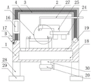
Fig. 1 is a schematic view of the overall front cross-sectional structure of the present invention.
Fig. 2 is a schematic view of the enlarged structure of part B of the present invention.
Fig. 3 is an enlarged schematic view of the part a of the present invention.
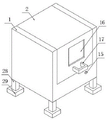
Fig. 4 is a schematic diagram of the overall three-dimensional structure of the present invention.
In the figure: 1. a base; 2. a noise reduction cover; 3. a cavity; 4. a sound insulating material; 5. a card slot; 6. clamping a plate; 7. a gasket; 8. a locking groove; 9. locking the groove; 10. a spring; 11. a lock lever; 12. a slider; 13. a chute; 14. a first telescopic rod; 15. a switch; 16. hollow glass; 17. a handle; 18. a storage chamber; 19. looping; 20. a valve; 21. a support frame; 22. a second telescopic rod; 23. a splint; 24. a bi-directional electric slide rail; 25. a connecting rod; 26. a cutting head; 27. a water spray pipe; 28. supporting legs; 29. a rubber pad; 30. a downpipe.
Detailed Description
The technical solutions in the embodiments of the present invention will be described clearly and completely with reference to the accompanying drawings in the embodiments of the present invention, and it is obvious that the described embodiments are only some embodiments of the present invention, not all embodiments. Based on the embodiments in the present invention, all other embodiments obtained by a person skilled in the art without creative efforts all belong to the protection scope of the present invention.
The utility model provides a precision cutting is with walking silk wire cut electrical discharge machining bed soon as shown in fig. 1-4, including base 1, the right side of base 1 upper surface is rotated and is connected with and falls the lid 2 of making an uproar, fall the inside of making an uproar lid 2 and seted up cavity 3, the inner wall of cavity 3 is provided with sound barrier material 4, draw-in groove 5 has been seted up all around of base 1 upper surface, the lower fixed surface that falls the lid 2 of making an uproar is connected with and draw-in groove 5 assorted cardboard 6, the both sides equal fixedly connected with of surface that cardboard 6 and draw-in groove 5 contacted seals up pad 7, the card locked groove 8 has been seted up in the left side of base 1 upper surface, the left side of locked groove 9 of locked groove 1 upper surface is seted up with card locked groove 8 assorted locked groove 9, the inner wall of locked groove 9 is provided with the mechanism, the locked mechanism includes spring 10, the lower side fixed connection of spring 10's lower extreme and the downside fixed connection of locked groove 9 inner wall, the upper end fixedly connected with card locked groove 8 assorted 11 of spring 10, the left and right sides equal fixedly connected with slider 12 of locked groove 11 of locking rod wall all, the left and right sides of locking rod 11 pole wall all the left and right sides fixed surface of the slider 12, the reduction of the workman's operation of the noise reduction of the life equipment that the noise reduction worker can cause the noise reduction to the long-term harm of the life to the life workman and the life that the noise reduction workman operates 14, the noise reduction crowd that the noise reduction of the long-time matched with the life is in the life that the life is connected with the life equipment, the life is greatly, the life of the noise reduction of the artificial noise reduction workman on the long-time.
As shown in fig. 1, the lower surfaces of two first telescopic rods 14 are fixedly connected with the lower side of the inner wall of a locking groove 9, so that the device is more stable in use and the safety in the working process is improved, a hollow glass 16 is fixedly connected at the center of the left side surface of a noise reduction cover 2, a handle 17 is fixedly connected at the lower side of the left side surface of the noise reduction cover 2, the inside of a cavity 3 is subjected to vacuum treatment, so that products in the device can better penetrate through the cavity, the use comfort of the device is improved, a storage cavity 18 is formed in the lower surface of a base 1, a ring opening 19 is formed in the upper side of the inner wall of the storage cavity 18, a downpipe 30 is fixedly connected at the lower side of the inner wall of the storage cavity 18, a valve 20 is fixedly connected to the pipe wall of the downpipe 30, waste water generated by the device can be uniformly collected and treated, so that the influence of the waste water on surrounding devices and people is avoided, a support frame 21 is fixedly connected to the upper surface of the base 1, the left side and the right side of the upper surface of the supporting frame 21 are fixedly connected with second telescopic rods 22, the output ends of the two second telescopic rods 22 are fixedly connected with clamping plates 23, products can be better fixed, the processing precision of the products is increased, the front side surface and the rear side surface of the base 1 are fixedly connected with two-way electric slide rails 24, the upper surface of the two-way electric slide rails 24 is fixedly connected with connecting rods 25, the left end of each connecting rod 25 is fixedly connected with a cutting head 26, the lower side of the cutting head 26 is fixedly connected with a water spray pipe 27, the right end of the water spray pipe 27 penetrates through the rear side of the inner wall of the base 1 and extends to the rear side surface of the inner wall of the base 1, flexible cutting is provided, the precision of the products is ensured, water moistening is carried out during processing, the damage of equipment is avoided, the four corners of the lower surface of the base 1 are fixedly connected with supporting legs 28, the lower surfaces of a plurality of the supporting legs 28 are fixedly connected with rubber pads 29, and the corrosion of the equipment caused by sewage under the equipment is avoided, avoid the noise generated by the operation of the equipment and the ground.
The utility model discloses the theory of operation: when the device is used, the switch 15 is pressed, the first telescopic rod 14 in the locking groove 9 is started, the first telescopic rod 14 drives the slider 12 to slide in the sliding groove 13, the slider 12 drives the lock rod 11 to be far away from the locking groove 8 to remove the limitation on the noise reduction cover 2, the handle 17 is pulled to drive the noise reduction cover 2 to rotate, the base 1 is far away, the device is further opened, the product is placed on the re-supporting frame 21, the clamp plate 23 is driven by the second telescopic rod 22 to clamp the product, the noise reduction cover 2 is closed, the lock rod 11 moves up and down under the elastic force of the spring 10, the noise reduction cover 2 can be easily clamped, the noise insulation material 4 in the noise reduction cover 2 is tightly connected with the base 1, the noise is reduced, the bidirectional electric sliding rail 24 is started, the bidirectional electric sliding rail 24 drives the cutting head 26 on the connecting rod 25 to process the product, the water spraying pipe 27 sprays water to moisten the device during processing, waste water generated by the device falls into the storage cavity 18 through the annular opening 19 to be uniformly collected, waste water in the storage cavity 18 is controlled by the valve 20 to be guided into the device from the waste water outlet 30.
Finally, it should be noted that: although the present invention has been described in detail with reference to the foregoing embodiments, it will be apparent to those skilled in the art that modifications and variations can be made in the embodiments or in part of the technical features of the embodiments without departing from the spirit and the scope of the invention.
Claims (8)
1. The utility model provides a precision cutting is with walking wire cut electrical discharge machining bed soon, includes base (1), its characterized in that: the right side of base (1) upper surface is rotated and is connected with and falls to make an uproar lid (2), fall the inside of making an uproar lid (2) and seted up cavity (3), the inner wall of cavity (3) is provided with sound insulation material (4), draw-in groove (5) have been seted up all around of base (1) upper surface, fall the lower fixed surface of making an uproar lid (2) and be connected with draw-in groove (5) assorted cardboard (6), the both sides equal fixedly connected with in surface that cardboard (6) and draw-in groove (5) contacted sealed pad (7), card locked groove (8) have been seted up in the left side of cardboard (6) lower surface, base (1) upper surface's left side seted up with card locked groove (8) assorted locked groove (9), the inner wall of locked groove (9) is provided with the halving mechanism.
2. The rapid-advancing wire-cutting machine tool for precision cutting according to claim 1, characterized in that: the mechanism is met to the lock includes spring (10), the downside fixed connection of the lower extreme of spring (10) and locked groove (9) inner wall, the upper end fixedly connected with and card locked groove (8) assorted locking lever (11) of spring (10), the equal fixedly connected with slider (12) of the left and right sides of locking lever (11) pole wall, the left and right sides of locked groove (9) inner wall all seted up with slider (12) assorted spout (13), two the first telescopic link (14) of the equal fixedly connected with of lower surface of slider (12), the left side fixed surface of base (1) is connected with and first telescopic link (14) assorted switch (15).
3. The rapid-advancing wire-cutting machine for precision cutting according to claim 2, characterized in that: the lower surfaces of the two first telescopic rods (14) are fixedly connected with the lower side of the inner wall of the locking groove (9).
4. The rapid-traverse wire cutting machine for precision cutting according to claim 1, wherein: the utility model discloses a noise reduction cover, including fall cover (2) left side surface, fall the center department fixedly connected with cavity glass (16) of cover (2) left side surface of making an uproar, fall the downside fixedly connected with handle (17) of cover (2) left side surface of making an uproar, vacuum treatment has been done to the inside of cavity (3).
5. The rapid-advancing wire-cutting machine tool for precision cutting according to claim 1, characterized in that: the storage cavity (18) is formed in the lower surface of the base (1), the annular opening (19) is formed in the upper side of the inner wall of the storage cavity (18), the downpipe (30) is fixedly connected to the lower side of the inner wall of the storage cavity (18), and the valve (20) is fixedly connected to the pipe wall of the downpipe (30).
6. The rapid-advancing wire-cutting machine tool for precision cutting according to claim 1, characterized in that: the last fixed surface of base (1) is connected with support frame (21), the equal fixedly connected with second telescopic link (22) in both sides about support frame (21) upper surface, two the equal fixedly connected with splint (23) of output of second telescopic link (22).
7. The rapid-advancing wire-cutting machine tool for precision cutting according to claim 1, characterized in that: the utility model discloses a two-way electronic slide rail of joint fixedly connected with in both sides surface around base (1), the last fixed surface of two-way electronic slide rail (24) is connected with connecting rod (25), the left end fixedly connected with cutting head (26) of connecting rod (25), downside fixedly connected with spray pipe (27) of cutting head (26), the right-hand member of spray pipe (27) runs through the rear side of base (1) inner wall and extends to its rear side surface.
8. The rapid-advancing wire-cutting machine tool for precision cutting according to claim 1, characterized in that: the equal fixedly connected with supporting leg (28) of four corners department of base (1) lower surface, it is a plurality of the equal fixedly connected with rubber pad (29) of lower surface of supporting leg (28).
Priority Applications (1)
| Application Number | Priority Date | Filing Date | Title |
|---|---|---|---|
| CN202220350818.6U CN217618236U (en) | 2022-02-22 | 2022-02-22 | Fast wire cutting machine for precision cutting |
Applications Claiming Priority (1)
| Application Number | Priority Date | Filing Date | Title |
|---|---|---|---|
| CN202220350818.6U CN217618236U (en) | 2022-02-22 | 2022-02-22 | Fast wire cutting machine for precision cutting |
Publications (1)
| Publication Number | Publication Date |
|---|---|
| CN217618236U true CN217618236U (en) | 2022-10-21 |
Family
ID=83645490
Family Applications (1)
| Application Number | Title | Priority Date | Filing Date |
|---|---|---|---|
| CN202220350818.6U Active CN217618236U (en) | 2022-02-22 | 2022-02-22 | Fast wire cutting machine for precision cutting |
Country Status (1)
| Country | Link |
|---|---|
| CN (1) | CN217618236U (en) |
-
2022
- 2022-02-22 CN CN202220350818.6U patent/CN217618236U/en active Active
Similar Documents
| Publication | Publication Date | Title |
|---|---|---|
| CN217618236U (en) | Fast wire cutting machine for precision cutting | |
| CN111163389B (en) | Head-mounted noise reduction equipment for metallurgy | |
| CN211758828U (en) | Cutting machine that dust removal effect is good | |
| CN208495979U (en) | A non-standard tooling that is convenient for machine tools to cut workpieces | |
| CN212123393U (en) | Cutting device is used in packing rubber production and processing | |
| CN211540496U (en) | Milling machine protector | |
| CN217556069U (en) | Glass-cutting fixing device | |
| CN207023661U (en) | A kind of toothbrush manufacturing machine hand | |
| CN214807965U (en) | Hydraulic door opener for fire rescue | |
| CN205599741U (en) | An automatic cutting and receiving device for a stamping machine tool | |
| CN212734531U (en) | Scrap recovery device for linear cutting machine | |
| CN210693004U (en) | Convenient-to-clean pneumatic peeling machine for data line production | |
| CN211519081U (en) | Stone material is carved with good drilling machine of stability | |
| CN210499474U (en) | Machine tool automatic door capable of being opened and closed manually in power-off state | |
| CN216029634U (en) | Safe type automatic blanking machine | |
| CN220699826U (en) | Cutting device of ultra-high pressure organosilicon mica board | |
| CN210350350U (en) | Novel line pressing equipment for production of electric appliance connecting lines | |
| CN222296460U (en) | A dust-proof air compressor | |
| CN215106386U (en) | Building curtain is with cutting calibrating device | |
| CN219581837U (en) | Protective cover of double-head saw | |
| CN212908477U (en) | Pressing mechanism for full-automatic terminal pressing machine | |
| CN222282567U (en) | An integrated power distribution system for CNC machine tools | |
| CN215615553U (en) | Dust keeper that high-speed steel processing was used | |
| CN222360364U (en) | Edge banding machine with cleaning function | |
| CN216578047U (en) | Front opening cutting device of flap machine |
Legal Events
| Date | Code | Title | Description |
|---|---|---|---|
| GR01 | Patent grant | ||
| GR01 | Patent grant |