CN217675111U - Belt conveyor layering roller frame capable of self-adapting to underground conditions - Google Patents
Belt conveyor layering roller frame capable of self-adapting to underground conditions Download PDFInfo
- Publication number
- CN217675111U CN217675111U CN202220510795.0U CN202220510795U CN217675111U CN 217675111 U CN217675111 U CN 217675111U CN 202220510795 U CN202220510795 U CN 202220510795U CN 217675111 U CN217675111 U CN 217675111U
- Authority
- CN
- China
- Prior art keywords
- bearing
- axis
- adjusting
- keel
- rods
- Prior art date
- Legal status (The legal status is an assumption and is not a legal conclusion. Google has not performed a legal analysis and makes no representation as to the accuracy of the status listed.)
- Expired - Fee Related
Links
- 230000007246 mechanism Effects 0.000 claims abstract description 29
- 238000009826 distribution Methods 0.000 claims abstract description 15
- 238000005253 cladding Methods 0.000 claims abstract description 5
- 238000013016 damping Methods 0.000 claims description 14
- 230000001681 protective effect Effects 0.000 claims description 6
- 230000001105 regulatory effect Effects 0.000 claims 6
- 208000024780 Urticaria Diseases 0.000 claims 1
- 239000003245 coal Substances 0.000 abstract description 16
- 230000006872 improvement Effects 0.000 abstract description 4
- 238000012423 maintenance Methods 0.000 description 7
- 230000008859 change Effects 0.000 description 5
- 229910000831 Steel Inorganic materials 0.000 description 3
- 239000000969 carrier Substances 0.000 description 3
- 238000005065 mining Methods 0.000 description 3
- 239000010959 steel Substances 0.000 description 3
- 230000003044 adaptive effect Effects 0.000 description 2
- 230000010354 integration Effects 0.000 description 2
- 238000010521 absorption reaction Methods 0.000 description 1
- 238000010586 diagram Methods 0.000 description 1
- 238000004519 manufacturing process Methods 0.000 description 1
- 238000012986 modification Methods 0.000 description 1
- 230000004048 modification Effects 0.000 description 1
- 230000009467 reduction Effects 0.000 description 1
Images


Landscapes
- Bearings For Parts Moving Linearly (AREA)
Abstract
The utility model relates to a belt conveyor layering bearing roller frame of self-adaptation downhole condition, including bearing keel, protection side net, direction slide rail, guide bar, roller frame, bearing roller, positioning mechanism, connect through the guide bar between two adjacent bearing keels, protection side net cladding is at the bearing keel surface to two direction slide rails that bearing keel axis symmetric distribution constitute a bearing group, and all establish two at least bearing groups in every bearing keel, all be connected with at least one roller frame in every bearing group, the bearing roller is erect to the roller. This is novel when satisfying to conveying system and bearing the weight of the location, can be according to the needs of coal transport operation in the mine tunnel, nimble adjustment direction of delivery, distance and conveying capacity have improved roller frame equipment simultaneously and have integrated and the modularization degree, very big improvement the conveyer layering bearing roller frame use in the mine tunnel, maintain flexibility, convenience and service environment's adaptability of operation.
Description
Technical Field
The utility model relates to a mining equipment, in particular to a belt conveyor layering roller frame of self-adaptation downhole condition.
Background
The mining shuttle car is an important device in the current inorganic rope traction conveying system, has large use amount and plays an important role, but in practical use, the current shuttle car device is found to have low working efficiency and complex operation when being connected with the inorganic rope traction system, a mine car and other bearing devices for operation on the one hand, and meanwhile, when a traction steel cable of the inorganic rope traction system is connected with the shuttle car, the tension of the traction steel cable is unstable due to the factors of poor matching property of the devices, unstable positioning of the steel cable and the like, so that the stability and the reliability of the traction acting force of the shuttle car are influenced; on the other hand, due to the fact that the working environment of a coal mine roadway and a mine site is severe, the precision of the track arrangement of the shuttle car operation is easily influenced, particularly, the width of the part of the track is not uniform, so that accidents such as derailment of the shuttle car are easily caused, the production working efficiency is influenced, and meanwhile, a large potential safety hazard is caused.
Therefore, in order to meet the current situation, a brand-new mining shuttle car structure is urgently needed to be developed so as to meet the actual use requirement.
SUMMERY OF THE UTILITY MODEL
The not enough to exist on the prior art, the utility model provides a belt conveyor layering bearing roller frame of self-adaptation downhole condition, this novel can be according to the use needs, nimble adjustment conveying roller frame structure, when satisfying to conveying system and bearing the location, can be according to the needs of coal conveying operation in the mine tunnel, nimble adjustment direction of delivery, distance and conveying capacity, the roller frame equipment integrates and the modularization degree has been improved simultaneously, effectively realize transporting fast in the underworkings, the flexibility and the convenience of field assembly regulation and equipment maintenance change operation, thereby very big improvement conveyer layering bearing roller frame use in the mine tunnel, the flexibility of maintenance operation, convenience and service environment's adaptability.
In order to achieve the above purpose, the present invention is realized by the following technical solution:
a belt conveyor layered roller carrier adaptive to underground conditions comprises bearing keels, a plurality of protective side nets, guide slide rails, guide rods, roller carriers and a positioning mechanism, wherein the bearing keels are of a closed annular frame structure with a rectangular axial section, the bearing keels are connected through at least two guide rods uniformly distributed around the axis of the bearing keels, the guide rods are hinged to the outer surfaces of the bearing keels through ratchet mechanisms and form 0-90-degree included angles with the axis of the bearing keels, the protective side nets are of a grid plate structure and cover the outer surfaces of the bearing keels, the guide slide rails are a plurality of, the two guide slide rails symmetrically distributed along the axis of the bearing keels form a bearing group, at least two bearing groups are arranged in each bearing keel, the bearing groups are distributed from top to bottom along the direction perpendicular to the axis of the bearing keels, the guide slide rails in the bearing groups are connected with the inner side faces of the bearing keels and form 0-90-degree included angles with the axis of the bearing keels, at least one roller carrier is connected with at least one roller carrier, the outer side faces of the roller carriers are connected with the roller carriers in a sliding way in a sliding mode that the roller carrier is connected with the roller carrier through a roller carrier shaft, and the roller carrier is distributed through a positioning mechanism, and the roller shafts are distributed through the guide rail, and the roller shafts are distributed between the roller carrier rollers.
The guide rod comprises a connecting base, telescopic adjusting rods, adjusting hinges and positioning pins, the connecting base is in a plate shape with a rectangular cross end face, the rear end face of the connecting base is hinged to the outer surface of the bearing keel through a ratchet mechanism, the connecting base and the ratchet mechanism are coaxially distributed, the axes of the connecting base and the outer surface of the bearing keel are vertically distributed, the four telescopic adjusting rods are uniformly distributed around the axis of the connecting base, the central angle between every two adjacent telescopic adjusting rods is 30-120 degrees, the axes of the telescopic adjusting rods and the side surface of the bearing keel are distributed in parallel, the rear end face of each telescopic adjusting rod is hinged to the side surface of the connecting base through the adjusting hinge, the axes of the telescopic adjusting rods and the side surface of the connecting base form an included angle of 0-90 degrees, the front end face of each telescopic adjusting rod exceeds the outer surface of the bearing keel by 0-2.5 times of the width of the bearing keel, at least one positioning pin is additionally arranged on the connecting base, the positioning pins and the axes of the connecting base are vertically distributed, and the connecting base and the side surface of the bearing keel are connected through the positioning pins.
Furthermore, the telescopic adjusting rod comprises at least two stages of adjusting rods, two bearing rods, a coupler and two adjusting screws of the telescopic rod mechanism, the two bearing rods are connected through the adjusting rod, the two bearing rods are coaxially distributed, the adjusting cavity is formed in each bearing rod and is coaxially distributed with the bearing rods, the two ends of each adjusting rod are embedded in the adjusting cavity, are coaxially distributed with the adjusting cavity and are in sliding connection with the side wall of the adjusting cavity, the two bearing rods are connected through the two adjusting screws uniformly distributed around the axis of the bearing rods, the two ends of each adjusting screw are in parallel distribution with the axis of the bearing rods and are respectively connected with the outer surfaces of the bearing rods through the adjusting screw holes, one ends of the bearing rods are connected with the connecting base, and the other ends of the bearing rods are connected with the coupler and are coaxially distributed with the coupler.
The roller frame comprises a bracket, two adjusting plates and guide wheels, the bracket is of a closed rectangular frame structure, the two adjusting plates are of a cross-shaped plate structure and are embedded in the bracket and hinged to the inner surface of the side wall of the bracket through a turntable mechanism, the adjusting plates are distributed in parallel with the inner side surface of the bracket and are symmetrically distributed on two sides of the axis of the bracket, an axle seat is arranged at each of four end surfaces of the adjusting plates and is connected with a carrier roller in a isomorphic way, the axis of the carrier roller is distributed in parallel, the roller surface of the carrier roller exceeds the upper end surface and the lower end surface of the bracket by at least 10 mm, the guide wheels are at least two and are symmetrically distributed on two sides of the axis of the bracket and are connected with the outer surface of the axis of the bracket, axles of the guide wheels are distributed in parallel with the axis of the carrier roller, the guide wheels are embedded in the guide slide rails and are connected with the guide slide rails in a sliding manner, at least two adjusting holes are uniformly distributed around the axis of the guide wheels are arranged on the side surface of the guide wheels, and a plurality of the guide rail grooves uniformly distributed along the axis of the guide rails are arranged at the bottoms of the grooves corresponding to be coated on the outer surface of the guide rails and are respectively connected with the guide rails and the guide wheels through the positioning holes and the adjusting holes.
Furthermore, the front section surface and the rear end surface of the bracket are respectively provided with an elastic damping block which is coaxially distributed with the front end surface and the rear end surface of the bracket respectively, the elastic damping blocks comprise at least two elastic lining plates, damping springs and elastic hinges, the rear end face of each elastic lining plate is connected with a damping spring, coaxially distributed and connected with the bracket through the damping spring, each elastic lining plate is of a plate-shaped structure with a rectangular cross section, every two adjacent elastic lining plates are hinged through an elastic hinge, and the front end face of each elastic lining plate forms an included angle of 0-60 degrees with the front end face and the rear end face of the bracket.
Further, positioning mechanism include draw-in groove, locating piece, reference column, connecting chain, the draw-in groove is "U" font slot-shaped structure, and two altogether and the cladding is outside the direction slide rail, and passes through locating piece connection between two draw-in grooves, the locating piece is the platelike structure that the rectangle is personally submitted to the cross section, locates the connecting hole of the coaxial distribution of locating piece on the locating piece, the reference column inlays in the locating hole, with the coaxial distribution of connecting hole and through sliding connection between connecting hole and locating piece, the reference column front end is located the locating piece front end off to connect in the draw-in groove surface through a connecting chain, the latter half inlays in locating hole and adjusting hole behind the reference column.
This is novel can be according to the use needs, nimble adjustment conveying roller frame structure, when satisfying to carrying on bearing the location conveying system, can be according to the needs of coal transport operation in the mine tunnel, nimble adjustment direction of delivery, distance and delivery capacity, the roller frame equipment integration and modularization degree have been improved simultaneously, effectively realize the transport of transporting fast in the underworkings, the flexibility and the convenience of operation are changed in field assembly regulation and plant maintenance, thereby very big improvement the use of conveyer layering bearing roller frame in the mine tunnel, the flexibility of maintenance operation, the adaptability of convenience and service environment.
Drawings
The present invention will be described in detail with reference to the accompanying drawings and specific embodiments.
FIG. 1 is a schematic structural view of the present invention;
FIG. 2 is a top view of a portion of the load keel;
fig. 3 is a schematic view of a partial structure of the telescopic adjusting rod.
Fig. 4 is a schematic structural diagram of the positioning mechanism.
Detailed Description
In order to make the technical means, creation features, achievement purposes and functions of the present invention easy to understand, the present invention is further described below with reference to the following embodiments.
As shown in fig. 1-4, a belt conveyor layered roller frame adaptive to downhole conditions comprises a bearing keel 1, a protective side net 2, a guide slide rail 3, guide rods 4, a roller frame 6, a roller 7 and a positioning mechanism 8, wherein the bearing keel 1 is a closed annular frame structure with a rectangular axial cross section, a plurality of bearing keels 1 are arranged, two adjacent bearing keels 1 are connected through at least two guide rods 4 uniformly distributed around the axis of the bearing keel 1, the guide rods 4 are hinged with the outer surface of the bearing keel 1 through a ratchet mechanism 5 and form an included angle of 0-90 degrees with the axis of the bearing keel 1, the protective side net 2 is of a grating plate structure and is coated on the outer surface of the bearing keel 1, the guide slide rail 3 is arranged, two guide slide rails 3 which are symmetrically distributed on the axis of the bearing keel 1 form a bearing group, at least two bearing groups are arranged in each bearing keel 1, the bearing groups are distributed from top to bottom along the direction which is vertical to the axis of the bearing keel 1, the guide slide rails 3 in the bearing groups are connected with the inner side surface of the bearing keel 1 and form an included angle of 0-90 degrees with the axis of the bearing keel 1, each bearing group is connected with at least one roller frame 6, the outer side surface of each roller frame 6 is connected with the guide slide rails 3 in a sliding manner, each roller frame 6 in the same bearing group is distributed along the axis direction of the bearing group, 1-2 carrier rollers 7 which are mutually distributed in parallel along the axis are additionally arranged on each roller frame 6, the axes of the carrier rollers 7 are vertically distributed with the axis of the bearing keel 1, and the roller frames are connected with the guide slide rails 3 through positioning mechanisms 8.
In order to improve the flexibility and convenience of practical use, the guide slide rail 3 and the roller frame 6 can be hinged through a ratchet mechanism 5.
In this embodiment, the guide rod 4 includes a connection base 41, telescopic adjustment rods 42, an adjustment hinge 43, and positioning pins 44, the connection base 41 is a plate with a rectangular cross-section, the rear end surface of the connection base 41 is hinged to the outer surface of the bearing keel 1 through a ratchet mechanism 5, the connection base 41 and the ratchet mechanism are coaxially distributed, the axes of the connection base 41 and the bearing keel 1 are vertically distributed, the telescopic adjustment rods 42 are four in number, the telescopic adjustment rods 42 are uniformly distributed around the axis of the connection base 41, the central angle between two adjacent telescopic adjustment rods 42 is 30 ° to 120 °, the axes of the telescopic adjustment rods 42 and the side surface of the bearing keel 1 are distributed in parallel, the rear end surface of each telescopic adjustment rod 42 is hinged to the side surface of the connection base 41 through the adjustment hinge 43, the axes of the telescopic adjustment rods 42 and the side surface of the connection base 41 form an included angle of 0 ° to 90 °, the front end surface of the telescopic adjustment rods 42 exceeds the outer surface of the bearing keel 1 by 0 to 2.5 times the width of the bearing keel 1, the connection base 41 is further provided with at least one positioning pin 44, the axis of the connection base 44 and the connection pin 41 and the side surface of the bearing keel 1 are connected through the positioning pins 44.
Meanwhile, the telescopic adjusting rod 42 includes at least two stages of adjusting rods 421, two bearing rods 422, a coupler 423 and adjusting screws 424 of the telescopic rod mechanism, the two bearing rods 422 are connected through the adjusting rod 421, the two bearing rods 421 and 422 are coaxially distributed, an adjusting cavity 425 coaxially distributed with the bearing rods 422 is arranged in the bearing rods 422, two ends of the adjusting rod are respectively embedded in the adjusting cavity 425, coaxially distributed with the adjusting cavity 425 and slidably connected with the side wall of the adjusting cavity 425, the two bearing rods 421 are additionally connected through two adjusting screws 424 uniformly distributed around the axis of the bearing rods 422, the adjusting screws 424 and the bearing rods 422 are axially distributed in parallel, two ends of the adjusting rod 424 are respectively connected with the outer surface of the bearing rods 422 through adjusting screw holes 426, one end of the bearing rods 422 is connected with the connecting base 41, and the other end of the bearing rods 422 is connected with the coupler 423 and coaxially distributed with the coupler 423.
Preferably, the adjusting screw 426 is embedded in the outer surface of the carrying rod, and the adjusting rod 421 is any one of a hydraulic telescopic rod, a pneumatic telescopic rod, a spring telescopic rod and a threaded telescopic rod.
It should be noted that the roller frame 6 includes a bracket 61, two adjusting plates 62 and a guide wheel 63, the bracket 61 is a closed rectangular frame structure, the adjusting plates 62 are in a cross-shaped plate structure, the two adjusting plates 62 are embedded in the bracket 61 and hinged to the inner surface of the side wall of the bracket 61 through a turntable mechanism 64, the adjusting plates 62 are distributed in parallel with the inner side surface of the bracket 61, the two adjusting plates 62 are symmetrically distributed on two sides of the axis of the bracket 61, four end surfaces of the adjusting plates 62 are provided with a shaft seat 65 and connected with the carrier roller 7 through the shaft seat 65, the axis of the carrier roller 7 is distributed in parallel, the roller surface of the carrier roller 7 exceeds the upper end surface and the lower end surface of the bracket 61 by at least 10 mm, the guide wheels 63 are at least two and symmetrically distributed on two sides of the axis of the bracket 61 and connected with the outer surface of the axis of the bracket 61, the shafts of the guide wheels 63 are distributed in parallel with the axis of the carrier roller 7, the guide wheel 63 is embedded in the guide slide rail 3 and connected with the guide rail 3 in a sliding manner, the side surface of the guide wheels 63 are provided with at least two adjusting holes 9 uniformly distributed along the axis of the guide rail 3, and the guide rail 3 are connected with the positioning holes 8, and the guide rail 3, and the guide wheels 8 are respectively covered with the positioning holes 8.
Meanwhile, the front section surface and the rear end surface of the bracket 61 are respectively provided with an elastic damping block 11, the elastic damping blocks 11 are respectively coaxially distributed with the front end surface and the rear end surface of the bracket 61, each elastic damping block 11 comprises an elastic lining plate 111, a damping spring 112 and an elastic hinge 113, the number of the elastic lining plates 111 is at least two, the rear end surface of each elastic lining plate 111 is connected with one damping spring 112 and coaxially distributed, and is connected with the bracket 61 through the damping spring 112, each elastic lining plate 111 is of a plate-shaped structure with a rectangular cross section, every two adjacent elastic lining plates 111 are hinged through the elastic hinge 113, and the front end surface of each elastic lining plate 111 and the front end surface and the rear end surface of the bracket 61 form an included angle of 0-60 degrees.
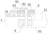
In addition, the positioning mechanism 8 includes two clamping grooves 81, two positioning blocks 82, a positioning column 83 and a connecting chain 84, the clamping grooves 81 are of a U-shaped groove-shaped structure and are coated outside the guide slide rail 3, the two clamping grooves 81 are connected through the positioning blocks 82, the positioning blocks 82 are of a plate-shaped structure with a rectangular cross section, the positioning blocks 82 are provided with connecting holes 85 which are coaxially distributed on the positioning blocks 82, the positioning columns 83 are embedded in the positioning holes 85, are coaxially distributed with the connecting holes 85 and are slidably connected with the positioning blocks 82 through the connecting holes 85, the front end surfaces of the positioning columns 83 are located outside the front end surfaces of the positioning blocks 82 and are connected with the outer surfaces of the clamping grooves 81 through the connecting chain 84, and the rear half parts of the positioning columns 83 are embedded in the positioning holes 9 and the adjusting holes 10.
This is novel in the concrete implementation, at first to constituting this neotype bearing keel and direction slide rail, the guide bar is connected, assemble each roller frame simultaneously, the bearing roller, positioning mechanism, obtain a plurality of bearing keels after the assembly, the roller frame and the protection side net that waits to assemble, then with each bearing keel after the assembly, the roller frame is transported to the mine tunnel in proper order through the transfer equipment under the protection side net that waits to assemble under the dispersed state, and along coal direction of delivery to each bearing keel after the assembly bearing keel who is in the part state, the roller frame and the protection side net that waits to assemble put on the scene, then to each bearing keel along coal direction of delivery, will be adjacent two bearing keels between through the guide bar in direction of delivery location, then according to coal volume of delivery along with horizontal plane vertical direction assembly remaining bearing keel, thereby obtain at least two-layer and coal direction of delivery direction mutually independent and parallelly connected transfer passage, and when bearing keel equipment, will bear the direction slide rail intercommunication in the bearing keel, will protect the protection side net bearing keel surface simultaneously, thereby realize bearing keel and protect the cladding operation safety.
In addition, when the assembly operation of each bearing keel is carried out, on one hand, the position of a roller frame in each bearing keel and the working position of a carrier roller in the roller frame are adjusted; on the other hand, the conveying belts for conveying coal are respectively carried and positioned by the carrier rollers in the roller frames, so that the requirements of assembling equipment and constructing a coal conveying system are met.
Meanwhile, in the concrete implementation and operation of the novel coal conveying device, on one hand, the distance between each bearing keel and the included angle between each bearing keel and the horizontal plane can be effectively adjusted by adjusting the length and the included angle of the guide rod, so that the aim of flexibly adjusting the novel structure and the coal conveying direction is fulfilled; on the other hand in operation, can dismantle the change to corresponding bearing keel and the equipment of being connected with bearing keel according to the needs of use and the needs of equipment maintenance operation in addition, overcome the drawback that traditional equipment change needs to carry out equipment whole shutdown change operation, improve coal conveying equipment operation's stability and reliability.
This is novel in operation, and the vibration that roller frame, bearing roller produced carries out elastic absorption when the elasticity snubber block that the accessible roller frame set up in addition was carried equipment coal to influence and interference that mechanical vibration when effectual reduction coal equipment carried caused equipment operating stability, further improve equipment operating stability.
This is novel can be as required, nimble adjustment conveying roller frame structure, when satisfying to conveying system and bearing the location, can be according to the needs of coal transport operation in the mine tunnel, nimble adjustment direction of delivery, distance and delivery capacity, the roller frame equipment integration and modularization degree have been improved simultaneously, effectively realize transporting fast in the tunnel in the pit, the flexibility and the convenience of field assembly regulation and equipment maintenance change operation, thereby very big improvement the use of conveyer layering bearing roller frame in the mine tunnel, the flexibility of maintenance operation, convenience and service environment's adaptability.
Those skilled in the art should understand that the present invention is not limited by the above embodiments. The foregoing embodiments and description have been made only for the purpose of illustrating the principles of the invention. The present invention can be further modified and improved without departing from the spirit and scope of the present invention. Such changes and modifications are intended to be within the scope of the claimed invention. The scope of the invention is defined by the appended claims and equivalents thereof.
Claims (6)
1. The utility model provides a belt conveyor layering bearing roller frame of self-adaptation downhole condition which characterized in that: the belt conveyor layered roller carrier capable of adapting to the underground condition comprises a bearing keel, a protective side net, a plurality of guide slide rails, guide rods, a roller frame, a carrier roller and a positioning mechanism, wherein the bearing keel is of a closed annular frame structure with a rectangular axial cross section, two adjacent bearing keels are connected through at least two guide rods uniformly distributed around the axis of the bearing keel, the guide rods are hinged with the outer surface of the bearing keel through a ratchet mechanism and form an included angle of 0-90 degrees with the axis of the bearing keel, the protective side net is of a grating plate structure and covers the outer surface of the bearing keel, the guide slide rails are a plurality of, and two guide slide rails symmetrically distributed along the axis of the bearing keel form a bearing group, and all establish two at least bearing groups in every bearing keel, bearing group is along the from top to bottom distribution with bearing keel axis vertical distribution direction, and bearing group in the direction slide rail be connected with bearing keel medial surface and be 0-90 contained angle with bearing keel axis, all be connected with at least one roll stand in every bearing group, roll stand lateral surface is in direction slide rail sliding connection, and each roll stand in same bearing group all distributes along bearing group axis direction, the roll stand establishes 1-2 bearing rollers that the axis distributes each other in parallel in addition, and distributes perpendicularly between bearing keel axis and the bearing keel axis, be connected through positioning mechanism between roll stand and the direction slide rail.
2. The belt conveyor layered idler rack of claim 1, wherein: the guide rod comprises a connecting base, telescopic adjusting rods, adjusting hinges and positioning pins, the connecting base is in a plate shape with a rectangular cross end, the rear end face of the connecting base is hinged to the outer surface of the bearing keel through a ratchet mechanism, the connecting base and the ratchet mechanism are coaxially distributed, the axes of the connecting base and the bearing keel are vertically distributed in addition, the four telescopic adjusting rods are uniformly distributed around the axis of the connecting base, the central angle between every two adjacent telescopic adjusting rods is 30-120 degrees, the axes of the telescopic adjusting rods and the side surface of the bearing keel are distributed in parallel, the rear end face of each telescopic adjusting rod is hinged to the side surface of the connecting base through the adjusting hinge, the included angle between the axis of each telescopic adjusting rod and the side surface of the connecting base is 0-90 degrees, the front end face of each telescopic adjusting rod exceeds the outer side surface of the bearing keel by 0 to 2.5 times of the width of the bearing keel, at least one positioning pin is additionally arranged on the connecting base, the positioning pins and the axis of the connecting base are vertically distributed, and the side surface of the bearing keel are connected through the positioning pins.
3. The belt conveyor layered idler rack of claim 2, wherein the belt conveyor layered idler rack is adapted to adapt downhole conditions to: the telescopic adjusting rod comprises at least two stages of adjusting rods of a telescopic rod mechanism, bearing rods, a coupler and adjusting screws, the bearing rods are two in number, the two bearing rods are connected through the adjusting rod, the two bearing rods are coaxially distributed, an adjusting cavity is formed in each bearing rod and coaxially distributed with the bearing rods, the two ends of each adjusting rod are embedded in the adjusting cavity respectively, are coaxially distributed with the adjusting cavity and are in sliding connection with the side wall of the adjusting cavity, the two bearing rods are connected with each other through the two adjusting screws surrounding the axis of each bearing rod, the adjusting screws are distributed in parallel with the axis of each bearing rod, the two ends of each adjusting rod are connected with the outer surface of each bearing rod through the adjusting screw holes respectively, one end of each bearing rod is connected with the connecting base, and the other end of each bearing rod is connected with the coupler and is coaxially distributed with the coupler.
4. The belt conveyor layered idler rack of claim 1, wherein: the roller frame include bracket, regulating plate, leading wheel, the bracket is closed rectangular frame structure, the regulating plate is "ten" font platelike structure, the regulating plate totally two, inlay in the bracket and pass through revolving stage mechanism with bracket lateral wall internal surface articulated, regulating plate and bracket medial surface parallel distribution and two regulating plate symmetric distributions in bracket axis both sides, a shaft base is all established to four terminal surface positions of regulating plate to isomorphism shaft base is connected with the bearing roller, bearing roller axis parallel distribution, and the bearing roller roll surface surpasss bracket up end and lower terminal surface at least 10 millimeters, at least two leading wheels, symmetric distribution are in bracket axis both sides to be connected with bracket axis surface, and leading wheel shaft and bearing roller axis parallel distribution, the leading wheel inlays in the direction slide rail and with direction slide rail within a definite time sliding connection, at least two regulation holes around direction wheel axis equipartition are established to the leading wheel lateral surface, and a plurality of locating holes along direction slide rail axis equipartition are established to the direction slide rail tank bottom that the regulation hole corresponds, positioning mechanism cladding is at the direction slide rail surface to be connected with direction slide rail and leading wheel through locating hole and regulation hole respectively.
5. The belt conveyor layered idler rack of claim 4, wherein said belt conveyor layered idler rack is adapted to adapt to downhole conditions, and comprises: the front section face and the rear end face of bracket all establish an elasticity snubber block, elasticity snubber block respectively with the bracket before terminal surface and the coaxial distribution of rear end face, the elasticity snubber block includes elasticity welt, damping spring, elasticity hinge, the elasticity welt is two at least, every elasticity welt rear end face all with a damping spring be connected and coaxial distribution to through damping spring and bracket connection, the plate-like structure of rectangle is personally submitted for the cross section to the elasticity welt, it is articulated through the elasticity hinge between two adjacent elasticity welts, and terminal surface before the elasticity welt and the bracket terminal surface be 0-60 contained angle.
6. The belt conveyor layered idler rack of claim 1, wherein: positioning mechanism include draw-in groove, locating piece, reference column, connecting chain, the draw-in groove is "U" font slot-shaped structure, two altogether and the cladding is outside the direction slide rail, and passes through locating piece connection between two draw-in grooves, the locating piece is the platelike structure of rectangle for the cross section, locates the connecting hole of the coaxial distribution of locating piece on the locating piece, the reference column inlays in the locating hole, with the coaxial distribution of connecting hole and through sliding connection between connecting hole and locating piece, the reference column front end face is located the locating piece front end face outward to be connected in the draw-in groove surface through a connecting chain, the latter half inlays in locating hole and adjusting hole in the reference column.
Priority Applications (1)
| Application Number | Priority Date | Filing Date | Title |
|---|---|---|---|
| CN202220510795.0U CN217675111U (en) | 2022-03-07 | 2022-03-07 | Belt conveyor layering roller frame capable of self-adapting to underground conditions |
Applications Claiming Priority (1)
| Application Number | Priority Date | Filing Date | Title |
|---|---|---|---|
| CN202220510795.0U CN217675111U (en) | 2022-03-07 | 2022-03-07 | Belt conveyor layering roller frame capable of self-adapting to underground conditions |
Publications (1)
| Publication Number | Publication Date |
|---|---|
| CN217675111U true CN217675111U (en) | 2022-10-28 |
Family
ID=83730747
Family Applications (1)
| Application Number | Title | Priority Date | Filing Date |
|---|---|---|---|
| CN202220510795.0U Expired - Fee Related CN217675111U (en) | 2022-03-07 | 2022-03-07 | Belt conveyor layering roller frame capable of self-adapting to underground conditions |
Country Status (1)
| Country | Link |
|---|---|
| CN (1) | CN217675111U (en) |
-
2022
- 2022-03-07 CN CN202220510795.0U patent/CN217675111U/en not_active Expired - Fee Related
Similar Documents
| Publication | Publication Date | Title |
|---|---|---|
| CN102556891B (en) | Slide lifter | |
| DE102021109792A1 (en) | Rail and running gear for idler diagnosis system on conveyors | |
| CN209275933U (en) | A kind of mining fast lifting transport device | |
| WO2008067802A1 (en) | Movable continuous conveyor and method for operating a movable continuous conveyor | |
| US6554145B1 (en) | Universal traversing assembly for legs of cranes or the like | |
| DE212011100101U1 (en) | storage warehouse | |
| CN102602659B (en) | Double-layer double-conveying belt type conveyer for mine | |
| AU2008241366B2 (en) | Support frame for conveyor rollers and method for providing access to conveyor rollers | |
| CN201711387U (en) | Walking cover plate device of coil car | |
| CN104775847A (en) | Coal mine conveying system | |
| EP1796991A1 (en) | Conveyor system | |
| CN219362280U (en) | Conveyer convenient to maintenance is shifted out to side direction | |
| CN207192188U (en) | Fluting medium linear transport device | |
| DE29710791U1 (en) | Transport system | |
| KR101065589B1 (en) | Chassis for Cable or Pipeline Trolleys | |
| CN211846101U (en) | Overhauling trolley, truss and pipe belt machine combination | |
| CN212923267U (en) | Semi-fixed intermediate frame for displacement type belt conveyor | |
| CN209835346U (en) | Adjustable shock-absorbing compensation chain guide device installed in pit | |
| CN202508560U (en) | Mining double-layer double-conveying belt conveyer | |
| CN212049121U (en) | Belt conveyor pinch roller | |
| CN107161609A (en) | The removable upper fortune conveying equipment of mine serialization exploitation | |
| CN112919043A (en) | Horizontal turning device of belt conveyor | |
| CN113232129A (en) | Movable prefabricated T-beam bottom die trolley | |
| CN215361326U (en) | Special transport vehicle for mine bridge type super-long rubber-tyred vehicle | |
| CN221342621U (en) | Pull-type upper carrier roller bracket for belt conveyor |
Legal Events
| Date | Code | Title | Description |
|---|---|---|---|
| GR01 | Patent grant | ||
| GR01 | Patent grant | ||
| CF01 | Termination of patent right due to non-payment of annual fee | ||
| CF01 | Termination of patent right due to non-payment of annual fee |
Granted publication date: 20221028 |