CN217791106U - Hook binding device - Google Patents
Hook binding device Download PDFInfo
- Publication number
- CN217791106U CN217791106U CN202222177369.2U CN202222177369U CN217791106U CN 217791106 U CN217791106 U CN 217791106U CN 202222177369 U CN202222177369 U CN 202222177369U CN 217791106 U CN217791106 U CN 217791106U
- Authority
- CN
- China
- Prior art keywords
- jaw
- rod
- hook
- hinged
- spring
- Prior art date
- Legal status (The legal status is an assumption and is not a legal conclusion. Google has not performed a legal analysis and makes no representation as to the accuracy of the status listed.)
- Active
Links
Images


Abstract
本申请公开了一种绑钩器,属于钓线与鱼钩的连接装置领域,用于绑钩,包括铰接为一体的上夹爪、下夹爪,所述上夹爪与下夹爪在外力作用下绕铰位置转动并使得上夹爪的首端与下夹爪的首端分离,所述上夹爪、下夹爪的首端分别加工有端部上卡齿、端部下卡齿,所述端部上卡齿与端部下卡齿配合实现鱼钩夹持;所述下夹爪在靠近端部下卡齿的位置处设置有下端部限位,下端部限位上开设有供绕线插杆插入的绕线插孔;所述下夹爪的一侧还通过侧杆铰接座铰接有侧压杆,侧压杆的自由端位于绕线插孔与端部下卡齿之间。鉴于上述技术方案,本申请降低了原有绑钩器的结构复杂度,提高了简单易用性,且在绑钩绕线过程中能够稳定地夹持鱼钩,保证鱼钩绑钩绕线过程中的姿态稳定性。

The application discloses a hook binding device, which belongs to the field of connecting devices for fishing lines and fishhooks. It is used for hook binding and includes an upper jaw and a lower jaw that are hinged as one. Under the action, it rotates around the hinge position and makes the head end of the upper jaw separate from the head end of the lower jaw. The upper clamping tooth at the end cooperates with the lower clamping tooth at the end to realize the fishhook clamping; the lower clamping jaw is provided with a lower limit stop at a position close to the lower clamp tooth at the end, and the lower limit limit is provided with a winding plug. The winding socket where the rod is inserted; one side of the lower jaw is also hinged with a side pressing rod through the hinged seat of the side rod, and the free end of the side pressing rod is located between the winding socket and the lower locking teeth at the end. In view of the above technical solution, the present application reduces the structural complexity of the original hook binding device, improves the ease of use, and can stably hold the fishhook during the hook binding winding process, ensuring that the fishhook binding hook winding process attitude stability in .
Description
技术领域technical field
本实用新型属于钓线与鱼钩的连接装置领域,具体地说,尤其涉及一种绑钩器。The utility model belongs to the field of connecting devices for fishing lines and fishhooks, in particular to a hook binding device.
背景技术Background technique
在垂钓过程中,与鱼钩连接的多为子线,子线通过绕绑的方式与鱼钩固定,而在绕绑的过程中由于鱼钩较小、子线细长,对一些中老年垂钓爱好者来讲,手持鱼钩并且同时操作鱼线进行绕绑作业,需要耗费较多的精力才能够完成。为解决这一问题,中国专利公开号为CN102792932A公开了一种绑钩器,其虽然能够克服一些电动绑钩器价格高、体积大、应对小号鱼钩较为费力的问题,但是根据其说明书的记载,其在使用时需要将鱼钩夹持在夹钩手柄上部与切削平面之间形成的夹口内,然后按照一定的绕线方式进行绕线,再手动转动转轴,夹持在夹口内的鱼钩随转轴旋转,转动大致一圈或二圈后,再下压压线帽上方的压线板,能使压线板下部的按压台阶部下压位于按压台阶部下方的鱼线,同时再转动转轴,鱼线便会改变走线方向,变成沿鱼钩方向向下走线。In the fishing process, most of the sub-lines are connected to the fishhook, and the sub-lines are fixed to the fishhook by winding and tying. In the process of winding and tying, because the fishhook is small and the sub-lines are slender, it is difficult for some middle-aged and elderly people to fish. For enthusiasts, holding a fishhook and operating the fishing line at the same time for winding and tying operations requires a lot of energy to complete. In order to solve this problem, Chinese Patent Publication No. CN102792932A discloses a hook tying device, although it can overcome the problems that some electric hook tying devices are expensive, bulky, and relatively laborious to deal with small fishhooks, but according to its specification It is recorded that when in use, the fishhook needs to be clamped in the jaw formed between the upper part of the hook handle and the cutting plane, and then the wire is wound according to a certain winding method, and then the rotating shaft is manually rotated to clamp the fish in the jaw. The hook rotates with the rotating shaft. After one or two rotations, press down on the pressing plate above the thread pressing cap, so that the pressing step at the lower part of the pressing plate can press down on the fishing line under the pressing step, and at the same time turn the rotating shaft , the fishing line will change the direction of the line, and become a downward line along the direction of the hook.
也就是说,中国专利公开号为CN102792932A的专利申请虽然公开了一种手动的绑钩器,但是其依旧具有一定的操作复杂度,操作人员在使用时具有一定的上手成本,无法做到简单易用。That is to say, although the patent application whose Chinese patent publication number is CN102792932A discloses a kind of manual hook binding device, it still has certain operational complexity, and the operator has certain getting started cost when using, and can't be simple and easy. use.
实用新型内容Utility model content
本实用新型的目的在于提供一种绑钩器,其降低了原有绑钩器的结构复杂度,提高了简单易用性,且在绑钩绕线过程中能够稳定地夹持鱼钩,保证鱼钩绑钩绕线过程中的姿态稳定性。The purpose of this utility model is to provide a hook binding device, which reduces the structural complexity of the original hook binding device, improves the ease of use, and can stably hold the fishhook during the hook winding process, ensuring Posture stability of hook tying and reeling.
为达到上述目的,本实用新型是通过以下技术方案实现的:In order to achieve the above object, the utility model is achieved through the following technical solutions:
一种绑钩器,包括铰接为一体的上夹爪、下夹爪,所述上夹爪与下夹爪在外力作用下绕铰位置转动并使得上夹爪首端的端部上卡齿与下夹爪首端的端部下卡齿分离,所述端部上卡齿与端部下卡齿配合实现鱼钩夹持;所述下夹爪在靠近端部下卡齿的位置处设置有下端部限位,下端部限位上开设有供绕线插杆插入的绕线插孔;所述下夹爪的一侧还通过侧杆铰接座铰接有侧压杆,侧压杆的自由端位于绕线插孔与端部下卡齿之间。A hook binding device, comprising an upper jaw and a lower jaw that are hinged as one, the upper jaw and the lower jaw rotate around the hinge position under the action of an external force and make the upper locking teeth at the head end of the upper jaw and the lower jaw The lower teeth at the end of the jaw head are separated, and the upper teeth at the end cooperate with the lower teeth at the end to realize the fishhook clamping; the lower jaw is provided with a lower limit at a position close to the lower teeth at the end, A winding socket for the insertion of the winding insertion rod is opened on the lower end limit; one side of the lower jaw is also hinged with a side pressure rod through the side rod hinge seat, and the free end of the side pressure rod is located in the winding socket between the lower teeth at the end.
进一步地讲,本申请中所述的下夹爪包括下本体,下本体具有与上夹爪通过铰接轴铰接的下铰接座,所述下本体的尾端开设有下弹簧放置孔,下弹簧放置孔内设置有与其一体的下弹簧定位杆;所述下弹簧定位杆与夹爪压簧的底端连接,所述夹爪压簧的底端位于下弹簧放置孔的内部。Further speaking, the lower jaw described in this application includes a lower body, the lower body has a lower hinge seat hinged with the upper jaw through a hinge shaft, the tail end of the lower body is provided with a lower spring placement hole, and the lower spring is placed A lower spring positioning rod integrated with it is arranged in the hole; the lower spring positioning rod is connected with the bottom end of the clamping jaw compression spring, and the bottom end of the clamping jaw compression spring is located inside the lower spring placement hole.
进一步地讲,本申请中所述的上夹爪包括上本体,上本体具有与其一体且和下铰接座铰接的上铰接座,上铰接座上加工有供铰接轴穿过的铰接孔;所述上本体的尾端开设有上弹簧放置孔,上弹簧放置孔的内部设置有与其一体的上弹簧定位杆;所述上弹簧定位杆与夹爪压簧的顶端连接,所述夹爪压簧的顶端位于上弹簧放置孔的内部。Further, the upper jaw described in the present application includes an upper body, the upper body has an upper hinge seat integrated with it and hinged with the lower hinge seat, and the upper hinge seat is processed with a hinge hole for the hinge shaft to pass through; the The tail end of the upper body is provided with an upper spring placement hole, and an upper spring positioning rod integrated with it is arranged inside the upper spring placement hole; the upper spring positioning rod is connected with the top of the jaw compression spring, and the gripper compression spring The top end is located inside the upper spring placement hole.
进一步地讲,本申请中所述的下夹爪在靠近尾端的位置处设置有向上夹爪所在方向延伸的夹爪导杆,所述上夹爪在与夹爪导杆对应的位置处开设有导向孔,夹爪导杆穿过导向孔并与导向孔的侧壁接触。Further speaking, the lower jaw described in this application is provided with a jaw guide rod extending in the direction of the upper jaw near the tail end, and the upper jaw is provided with a The guide hole, the jaw guide rod passes through the guide hole and is in contact with the side wall of the guide hole.
进一步地讲,本申请中所述的端部上卡齿位于上端部限位的端面,所述上端部限位由上夹爪的首端下夹爪的首端所在方向向下弯折而成;所述端部上卡齿与上端部限位的内侧面之间形成限位斜面。Further speaking, the upper clamping tooth at the end described in this application is located on the end surface of the upper end stop, and the upper end stop is formed by bending the head end of the upper jaw and the head end of the lower jaw downward in the direction where it is located. ; A limiting slope is formed between the upper locking teeth of the end and the inner surface of the upper end limiting.
进一步地讲,本申请中所述的端部下卡齿与下端部限位的衔接位置处形成限位斜面。Further speaking, a limiting slope is formed at the engagement position between the lower locking teeth at the end described in this application and the limiting at the lower end.
进一步地讲,本申请中所述的侧压杆包括压杆本体,压杆本体通过压杆铰接部铰接于侧杆铰接座上;所述压杆本体的尾端设置有与其一体的压持尾部,压持尾部与下夹爪之间连接有侧压杆压簧;所述压杆本体的首端设置有与其一体的压杆自由端。Furthermore, the side pressure rod described in this application includes a pressure rod body, which is hinged to the hinge seat of the side rod through the pressure rod hinge; the tail end of the pressure rod body is provided with a pressure tail integrated with , a side compression rod compression spring is connected between the pressing tail and the lower jaw; the head end of the compression rod body is provided with a free end of the compression rod integral with it.
进一步地讲,本申请中所述的下夹爪的底部连接有调节立杆,调节立杆插接于调节套筒中并通过调节套筒上的调节旋钮旋紧固定;所述调节套筒固定连接于底座上。Furthermore, the bottom of the lower jaw described in this application is connected with an adjustment pole, which is inserted into the adjustment sleeve and fixed by the adjustment knob on the adjustment sleeve; the adjustment sleeve is fixed connected to the base.
与现有技术相比,本实用新型的有益效果是:Compared with the prior art, the beneficial effects of the utility model are:
1、本实用新型通过上夹爪、下夹爪、侧压杆及绕线插杆的有效配合,能够实现绑钩绕线过程中鱼钩姿态的稳定性,且操作简单,易于上手。1. Through the effective cooperation of the upper jaw, lower jaw, side pressure rod and winding insertion rod, the utility model can realize the stability of the fishhook posture during the hook binding and winding process, and the operation is simple and easy to use.
2、本实用新型通过设置夹爪导杆及导向孔的结构形式,能够保证上夹爪、下夹爪在夹持鱼钩的过程中自身运动轨迹的稳定性,保证端部上卡齿、端部下卡齿的配合精度,避免上夹爪、下夹爪绕铰接位置处的左右晃动。2. The utility model can ensure the stability of the movement track of the upper jaw and the lower jaw in the process of clamping the fishhook by setting the structure of the jaw guide rod and the guide hole, and ensure the upper clamping teeth of the end and the end The matching accuracy of the lower teeth prevents the left and right shaking of the upper and lower jaws around the hinged position.
3、本实用新型通过增加限位斜面,并使得限位斜面能够与端部下卡齿、端部上卡齿配合,提高了对鱼钩尾部钩基处的适应性,避免鱼钩尾部钩基对端部下卡齿、端部上卡齿夹持稳定性的影响。3. The utility model improves the adaptability to the hook base at the tail of the fishhook by increasing the limit slope, and enables the limit slope to cooperate with the lower locking teeth at the end and the upper locking teeth at the end, and avoids the hook base at the tail of the fishhook from being paired. The impact of the clamping stability of the lower teeth at the end and the upper teeth at the end.
4、本实用新型通过在端部下卡齿的位置处设置下端部限位,能够实现对上端部限位的有效支撑与配合,继而确保端部上卡齿、端部下卡齿的配合精度,便于实现对鱼钩钩柄部位的夹持。4. The utility model can realize the effective support and cooperation of the upper end limit by setting the lower end stopper at the position of the lower end catch, and then ensure the matching accuracy of the upper end catch and the lower end catch, which is convenient Realize the clamping of the shank of the fishhook.
附图说明Description of drawings
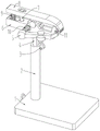
图1是本实用新型的立体图一。Fig. 1 is a perspective view one of the utility model.
图2是本实用新型的立体图二。Fig. 2 is a perspective view two of the utility model.
图3是本实用新型中下夹爪的结构示意图。Fig. 3 is a structural schematic diagram of the middle and lower jaws of the present invention.
图4是图3中A部分的放大图。Fig. 4 is an enlarged view of part A in Fig. 3 .
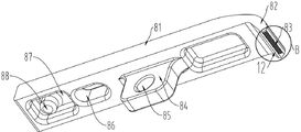
图5是本实用新型中上夹爪的结构示意图。Fig. 5 is a schematic structural view of the upper jaw in the utility model.
图6是图5中B部分的放大图。Fig. 6 is an enlarged view of part B in Fig. 5 .
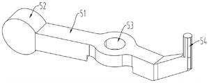
图7是本实用新型中侧压杆的结构示意图一。Fig. 7 is a schematic diagram of the first structure of the side pressure rod in the utility model.
图8是本实用新型中侧压杆的结构示意图二。Fig. 8 is the second structural diagram of the side pressure rod in the utility model.
图中:1、底座;2、调节套筒;3、调节旋钮;4、调节立杆;5、侧压杆;6、下夹爪;7、夹爪导杆;8、上夹爪;9、夹爪压簧;10、侧压杆压簧;11、绕线插杆;12、限位斜面。In the figure: 1. Base; 2. Adjusting sleeve; 3. Adjusting knob; 4. Adjusting vertical rod; 5. Side pressure rod; 6. Lower jaw; 7. Gripper guide rod; 1. Claw pressure spring; 10. Side pressure rod pressure spring; 11. Winding insertion rod; 12. Limiting slope.
51、压杆本体;52、压持尾部;53、压杆铰接部;54、压杆自由端。51. The main body of the compression rod; 52. The tail of the compression rod; 53. The hinged part of the compression rod; 54. The free end of the compression rod.
61、下本体;62、下铰接座;63、铰接轴;64、下端部限位;65、端部下卡齿;66、侧杆铰接座;67、下弹簧放置孔;68、下弹簧定位杆;69、绕线插孔。61, lower body; 62, lower hinged seat; 63, hinged shaft; 64, lower end stopper; 65, lower latch at the end; 66, side rod hinged seat; 67, lower spring placement hole; 68, lower spring positioning rod ; 69, winding jack.
81、上本体;82、上端部限位;83、端部上卡齿;84、上铰接座;85、铰接孔;86、导向孔;87、上弹簧放置孔;88、上弹簧定位杆。81, the upper body; 82, the upper end limit; 83, the upper locking teeth at the end; 84, the upper hinge seat; 85, the hinge hole; 86, the guide hole; 87, the upper spring placement hole; 88, the upper spring positioning rod.
具体实施方式Detailed ways
下面结合附图对本实用新型所述的技术方案作进一步地描述说明。在进行详细说明的段落中所涉及到的方位名词,仅为方便本领域的技术人员依照附图所展示的视觉方位理解本申请所记载的技术方案。除另有明确的规定和限定外,术语“设置”“安装”、“连接”等应做广义理解,对于本领域的普通技术人员而言,可以根据具体情况理解上述术语在本实用新型中的具体含义。Below in conjunction with accompanying drawing, the technical scheme described in the utility model is further described and illustrated. The orientation nouns involved in the detailed description are only for the convenience of those skilled in the art to understand the technical solutions described in the application according to the visual orientation shown in the drawings. Unless otherwise specified and limited, the terms "setting", "installation", "connection", etc. should be understood in a broad sense, and those of ordinary skill in the art can understand the meaning of the above terms in this utility model according to the specific situation Concrete meaning.
如图1至图2所示,一种绑钩器,包括铰接于一体的下夹爪6、上夹爪8,其中所述下夹爪6与调节立杆4连接,调节立杆4插接于调节套筒2中并通过调节旋钮3与调节套筒2固定,调节旋钮3通过螺纹方式旋接于所述调节套筒2。所述调节套筒2的底端位于底座1上,底座1为矩形板体。As shown in Figures 1 to 2, a hook binding device includes a lower jaw 6 and an
参见图3、图4,所述下夹爪6包括下本体61,在下本体61的中部位置处设置有与其一体的下铰接座62,下铰接座62通过铰接轴63与上夹爪8铰接。所述下本体61的尾部开设有容纳下弹簧定位杆68的下弹簧放置孔67,在下弹簧放置孔67与下铰接座62之间的下本体61上连接有夹爪导杆7,所述夹爪导杆7与所处位置处的下本体61垂直设置。Referring to Fig. 3 and Fig. 4, the lower jaw 6 includes a
所述下本体61在远离其首端加工有若干凹槽构成的端部下卡齿65,端部下卡齿65朝向上夹爪8首端所在方向;在下本体61靠近端部下卡齿65的两侧对称设置有上夹爪8所在方向延伸的下端部限位64,端部下卡齿65位于相邻的下端部限位64之间。同时,下本体61上相邻的下端部限位64能够在下本体61上形成容纳鱼钩尾部钩基的空间。所述下端部限位64上开设有绕线插孔69,绕线插孔69内插接有绕线插杆11,绕线插杆11能够在绕线插孔69内移动,以使得在绕线插杆11上弯折的鱼线得以抽出或限位。所述端部下卡齿65所处端面与下端部限位64的衔接位置处加工有限位斜面12,限位斜面12在该位置构成凹槽结构。The
所述下本体61的一侧固定连接有与其一体的侧杆铰接座66,侧杆铰接座66上铰接有侧压杆5。One side of the
参考图5、图6,所述上夹爪8包括上本体81,上本体81具有与下铰接座62铰接的上铰接座84,上铰接座84上开设有与铰接轴63配合的铰接孔85。所述上铰接座84位于上本体81的中部位置处,在上本体81的尾端设置有与下弹簧放置孔67对应的上弹簧放置孔87,上弹簧放置孔87内固定有与其一体的上弹簧定位杆88,上弹簧定位杆88与下弹簧定位杆68之间连接有夹爪压簧9,夹爪压簧9的两端分别位于上弹簧放置孔87、下弹簧放置孔67内。5 and 6, the
所述上本体81在上弹簧放置孔87、上铰接座84之间的位置处加工有导向孔86,导向孔86与下本体61上的夹爪导杆7对应,且夹爪导杆7穿过导向孔86并与导向孔86的侧壁接触。The
所述上本体81在其前端设置有向下弯折的上端部限位82,上端部限位82的底部端面加工有若干凹槽构成的端部上卡齿83,端部上卡齿83所处端面与上端部限位82的内侧面的衔接位置处设置有限位斜面12。上本体81、下本体61上的限位斜面12配合,能够实现对鱼钩中钩基部位的容纳,避免钩基部位在绑钩绕线过程中对端部下卡齿65、端部上卡齿83的影响。初始状态下,所述上端部限位82的内侧面与下端部限位64的外端面贴合,并得到下端部限位64的支撑。The
参考图7至图8,所述侧压杆5包括压杆本体51,压杆本体51在其中部具有与侧杆铰接座66铰接的压杆铰接部53,压杆铰接部53能够绕铰接轴转动。所述压杆本体51的尾部具有圆板结构的压持尾部52,压持尾部52与对应的下夹爪6之间连接有侧压杆压簧10。所述压杆本体51的压杆自由端54在与下夹爪6接触时位于所述绕线插孔69、端部下卡齿65之间,其作用在于将在绕线插杆11处弯折的鱼线压于下夹爪6的下本体61上,待绕线完成抽线的过程中,通过对压持尾部52施压使得压杆自由端54与下本体61脱离,抽出绕线插杆11使得该处预留弯折的鱼线得以脱离。为避免压杆自由端54对所压住的鱼线造成损伤,可在压杆自由端54上套接有弹性材料,例如橡胶材料、硅胶材料制成的套筒结构。With reference to Fig. 7 to Fig. 8, described side strut 5 comprises
在上述实施例的基础上,本实用新型继续对其中涉及到的技术特征及该技术特征在本实用新型中所起到的功能、作用进行详细的描述,以帮助本领域的技术人员充分理解本实用新型的技术方案并且予以重现。On the basis of the above embodiments, the utility model continues to describe in detail the technical features involved in it and the functions and effects of the technical features in the utility model, so as to help those skilled in the art fully understand the present invention. The technical scheme of the utility model is reproduced.
本实用新型在使用时,首先将底座1放置于平台,通过调节旋钮3实现调节立杆4与调节套筒2相对高度的调节,调节完成后通过旋入调节旋钮3使得调节旋钮3的端面压于调节立杆4上,进而完成调节立杆4与调节套筒2的相对固定。When the utility model is in use, the base 1 is first placed on the platform, and the adjustment of the relative height of the vertical rod 4 and the
操作人员对上夹爪8的尾端施加作用力,上夹爪8的尾端靠近下夹爪6的尾端,并同时使得上夹爪8、下夹爪6上的端部上卡齿83、端部下卡齿65相互远离,位于上夹爪8、下夹爪6尾端的夹爪压簧9被压缩。The operator applies force to the tail end of the
操作人员将鱼钩尾部放入至端部下卡齿65的凹槽中,鱼钩尾部的钩基部位位于限位斜面12位置处。操作人员松开上夹爪8、下夹爪6的尾部,在夹爪压簧9复位作用力的作用下,端部下卡齿65、端部上卡齿83重新靠近并实现对鱼钩钩柄位置处的夹紧,鱼钩的钩腹、钩弯处于端部下卡齿65、端部上卡齿83的外部。The operator puts the tail of the fishhook into the groove of the
操作人员下压侧压杆5的压持尾部52,使得压杆自由端54与下夹爪6脱离,在绕线插孔69中插入绕线插杆11,将鱼线弯折后挂于绕线插杆11上,弯折后鱼线较短的一端沿着钩柄向钩底所在方向并行,将鱼线较长的一端形成一个绳圈,手持绳圈或通过工具将构成绳圈的鱼线转动以形成自身交叉,交叉后的绳圈将鱼钩的钩底套入其中,使得钩柄及钩柄处的较短鱼线被套入的绳圈绑住,重复上述交叉缠绕的方法5至6圈后,从打开的端部下卡齿65、端部上卡齿83中取下鱼钩,手压压持尾部52并抽出绕线插杆11,使得原本挂在绕线插杆11上的鱼线与绕线插杆11脱离,分别拉紧较短一端的鱼线、较长一端的鱼线,即可实现鱼线与鱼钩钩柄位置处的绑紧。The operator presses down the
最后,虽然本说明书按照实施方式加以描述,但并非每个实施方式仅包含一个独立的技术方案,说明书的这种叙述方式仅仅是为清楚起见,本领域技术人员应当将说明书作为一个整体,各实施例中的技术方案也可以经适当组合,形成本领域技术人员可以理解的其他实施方式。Finally, although this description is described according to implementation modes, not each implementation mode only includes an independent technical solution. This description in the description is only for the sake of clarity. The technical solutions in the examples can also be properly combined to form other implementations that can be understood by those skilled in the art.
Claims (8)
Priority Applications (1)
| Application Number | Priority Date | Filing Date | Title |
|---|---|---|---|
| CN202222177369.2U CN217791106U (en) | 2022-08-18 | 2022-08-18 | Hook binding device |
Applications Claiming Priority (1)
| Application Number | Priority Date | Filing Date | Title |
|---|---|---|---|
| CN202222177369.2U CN217791106U (en) | 2022-08-18 | 2022-08-18 | Hook binding device |
Publications (1)
| Publication Number | Publication Date |
|---|---|
| CN217791106U true CN217791106U (en) | 2022-11-15 |
Family
ID=83977116
Family Applications (1)
| Application Number | Title | Priority Date | Filing Date |
|---|---|---|---|
| CN202222177369.2U Active CN217791106U (en) | 2022-08-18 | 2022-08-18 | Hook binding device |
Country Status (1)
| Country | Link |
|---|---|
| CN (1) | CN217791106U (en) |
-
2022
- 2022-08-18 CN CN202222177369.2U patent/CN217791106U/en active Active
Similar Documents
| Publication | Publication Date | Title |
|---|---|---|
| US4005722A (en) | Tool for flossing teeth under a permanent bridge | |
| CN110661153A (en) | Wiring device and wiring system for J-shaped wire clamp | |
| CN217791106U (en) | Hook binding device | |
| KR20200138951A (en) | Hair pin | |
| CN113142149B (en) | Fish hook tying device | |
| EP1911601A1 (en) | A plate clamper with a handle for releasing a holder | |
| CN215093316U (en) | Novel chip extractor | |
| CN113081228A (en) | Caudal tooth extractor for orthopedic pedicle screws | |
| CN218552301U (en) | Buccal mucosa traction device and oral cavity traction assembly | |
| CN215187866U (en) | Protection box for energy gateway equipment | |
| TWI357300B (en) | Tying machine used in agriculture | |
| CN115026326A (en) | A tool holder structure with anti-pinch function for CNC machine tools | |
| CN220712503U (en) | Egg picker | |
| US8479751B2 (en) | Plier-type power flosser | |
| CN210897681U (en) | A J-type clip wiring device for fixing branch lines | |
| CN201154463Y (en) | Special pliers for pulling insulator R-type pin | |
| CN218528802U (en) | Circumcision suturing device of prepuce anastomat | |
| CN219600453U (en) | Clamping assembly for disposable biological bags | |
| CN205424355U (en) | Drive -by -wire is from rapping bar | |
| CN219019627U (en) | A grafting fixation device | |
| CN222029451U (en) | A high stability hydraulic pliers | |
| CN221977090U (en) | A leakage detector for electric power construction | |
| CN222515971U (en) | Fishhook binding wire fixing structure and binding wire fixing device | |
| CN221814151U (en) | Clamping pliers convenient to fix | |
| CN215828062U (en) | HDMI pencil storage device |
Legal Events
| Date | Code | Title | Description |
|---|---|---|---|
| GR01 | Patent grant | ||
| GR01 | Patent grant | ||
| PP01 | Preservation of patent right |
Effective date of registration: 20260401 Granted publication date: 20221115 |