CN217852603U - Kitchen appliance - Google Patents
Kitchen appliance Download PDFInfo
- Publication number
- CN217852603U CN217852603U CN202221198596.7U CN202221198596U CN217852603U CN 217852603 U CN217852603 U CN 217852603U CN 202221198596 U CN202221198596 U CN 202221198596U CN 217852603 U CN217852603 U CN 217852603U
- Authority
- CN
- China
- Prior art keywords
- battery pack
- installation
- kitchen appliance
- mounting
- limiting
- Prior art date
- Legal status (The legal status is an assumption and is not a legal conclusion. Google has not performed a legal analysis and makes no representation as to the accuracy of the status listed.)
- Active
Links
Images




Classifications
-
- B—PERFORMING OPERATIONS; TRANSPORTING
- B01—PHYSICAL OR CHEMICAL PROCESSES OR APPARATUS IN GENERAL
- B01F—MIXING, e.g. DISSOLVING, EMULSIFYING OR DISPERSING
- B01F35/00—Accessories for mixers; Auxiliary operations or auxiliary devices; Parts or details of general application
- B01F35/30—Driving arrangements; Transmissions; Couplings; Brakes
- B01F35/32—Driving arrangements
- B01F35/32005—Type of drive
- B01F35/32025—Battery driven
-
- A—HUMAN NECESSITIES
- A47—FURNITURE; DOMESTIC ARTICLES OR APPLIANCES; COFFEE MILLS; SPICE MILLS; SUCTION CLEANERS IN GENERAL
- A47J—KITCHEN EQUIPMENT; COFFEE MILLS; SPICE MILLS; APPARATUS FOR MAKING BEVERAGES
- A47J43/00—Implements for preparing or holding food, not provided for in other groups of this subclass
- A47J43/04—Machines for domestic use not covered elsewhere, e.g. for grinding, mixing, stirring, kneading, emulsifying, whipping or beating foodstuffs, e.g. power-driven
- A47J43/07—Parts or details, e.g. mixing tools, whipping tools
-
- A—HUMAN NECESSITIES
- A47—FURNITURE; DOMESTIC ARTICLES OR APPLIANCES; COFFEE MILLS; SPICE MILLS; SUCTION CLEANERS IN GENERAL
- A47J—KITCHEN EQUIPMENT; COFFEE MILLS; SPICE MILLS; APPARATUS FOR MAKING BEVERAGES
- A47J19/00—Household machines for straining foodstuffs; Household implements for mashing or straining foodstuffs
-
- A—HUMAN NECESSITIES
- A47—FURNITURE; DOMESTIC ARTICLES OR APPLIANCES; COFFEE MILLS; SPICE MILLS; SUCTION CLEANERS IN GENERAL
- A47J—KITCHEN EQUIPMENT; COFFEE MILLS; SPICE MILLS; APPARATUS FOR MAKING BEVERAGES
- A47J43/00—Implements for preparing or holding food, not provided for in other groups of this subclass
- A47J43/04—Machines for domestic use not covered elsewhere, e.g. for grinding, mixing, stirring, kneading, emulsifying, whipping or beating foodstuffs, e.g. power-driven
- A47J43/044—Machines for domestic use not covered elsewhere, e.g. for grinding, mixing, stirring, kneading, emulsifying, whipping or beating foodstuffs, e.g. power-driven with tools driven from the top side
-
- A—HUMAN NECESSITIES
- A47—FURNITURE; DOMESTIC ARTICLES OR APPLIANCES; COFFEE MILLS; SPICE MILLS; SUCTION CLEANERS IN GENERAL
- A47J—KITCHEN EQUIPMENT; COFFEE MILLS; SPICE MILLS; APPARATUS FOR MAKING BEVERAGES
- A47J43/00—Implements for preparing or holding food, not provided for in other groups of this subclass
- A47J43/04—Machines for domestic use not covered elsewhere, e.g. for grinding, mixing, stirring, kneading, emulsifying, whipping or beating foodstuffs, e.g. power-driven
- A47J43/07—Parts or details, e.g. mixing tools, whipping tools
- A47J43/0705—Parts or details, e.g. mixing tools, whipping tools for machines with tools driven from the upper side
- A47J43/0711—Parts or details, e.g. mixing tools, whipping tools for machines with tools driven from the upper side mixing, whipping or cutting tools
-
- B—PERFORMING OPERATIONS; TRANSPORTING
- B01—PHYSICAL OR CHEMICAL PROCESSES OR APPARATUS IN GENERAL
- B01F—MIXING, e.g. DISSOLVING, EMULSIFYING OR DISPERSING
- B01F33/00—Other mixers; Mixing plants; Combinations of mixers
- B01F33/50—Movable or transportable mixing devices or plants
- B01F33/501—Movable mixing devices, i.e. readily shifted or displaced from one place to another, e.g. portable during use
- B01F33/5011—Movable mixing devices, i.e. readily shifted or displaced from one place to another, e.g. portable during use portable during use, e.g. hand-held
-
- H—ELECTRICITY
- H01—ELECTRIC ELEMENTS
- H01M—PROCESSES OR MEANS, e.g. BATTERIES, FOR THE DIRECT CONVERSION OF CHEMICAL ENERGY INTO ELECTRICAL ENERGY
- H01M50/00—Constructional details or processes of manufacture of the non-active parts of electrochemical cells other than fuel cells, e.g. hybrid cells
- H01M50/20—Mountings; Secondary casings or frames; Racks, modules or packs; Suspension devices; Shock absorbers; Transport or carrying devices; Holders
- H01M50/244—Secondary casings; Racks; Suspension devices; Carrying devices; Holders characterised by their mounting method
-
- H—ELECTRICITY
- H01—ELECTRIC ELEMENTS
- H01M—PROCESSES OR MEANS, e.g. BATTERIES, FOR THE DIRECT CONVERSION OF CHEMICAL ENERGY INTO ELECTRICAL ENERGY
- H01M50/00—Constructional details or processes of manufacture of the non-active parts of electrochemical cells other than fuel cells, e.g. hybrid cells
- H01M50/20—Mountings; Secondary casings or frames; Racks, modules or packs; Suspension devices; Shock absorbers; Transport or carrying devices; Holders
- H01M50/247—Mountings; Secondary casings or frames; Racks, modules or packs; Suspension devices; Shock absorbers; Transport or carrying devices; Holders specially adapted for portable devices, e.g. mobile phones, computers, hand tools or pacemakers
-
- H—ELECTRICITY
- H01—ELECTRIC ELEMENTS
- H01M—PROCESSES OR MEANS, e.g. BATTERIES, FOR THE DIRECT CONVERSION OF CHEMICAL ENERGY INTO ELECTRICAL ENERGY
- H01M50/00—Constructional details or processes of manufacture of the non-active parts of electrochemical cells other than fuel cells, e.g. hybrid cells
- H01M50/20—Mountings; Secondary casings or frames; Racks, modules or packs; Suspension devices; Shock absorbers; Transport or carrying devices; Holders
- H01M50/262—Mountings; Secondary casings or frames; Racks, modules or packs; Suspension devices; Shock absorbers; Transport or carrying devices; Holders with fastening means, e.g. locks
-
- A—HUMAN NECESSITIES
- A47—FURNITURE; DOMESTIC ARTICLES OR APPLIANCES; COFFEE MILLS; SPICE MILLS; SUCTION CLEANERS IN GENERAL
- A47J—KITCHEN EQUIPMENT; COFFEE MILLS; SPICE MILLS; APPARATUS FOR MAKING BEVERAGES
- A47J19/00—Household machines for straining foodstuffs; Household implements for mashing or straining foodstuffs
- A47J19/02—Citrus fruit squeezers; Other fruit juice extracting devices
-
- A—HUMAN NECESSITIES
- A47—FURNITURE; DOMESTIC ARTICLES OR APPLIANCES; COFFEE MILLS; SPICE MILLS; SUCTION CLEANERS IN GENERAL
- A47J—KITCHEN EQUIPMENT; COFFEE MILLS; SPICE MILLS; APPARATUS FOR MAKING BEVERAGES
- A47J43/00—Implements for preparing or holding food, not provided for in other groups of this subclass
- A47J43/04—Machines for domestic use not covered elsewhere, e.g. for grinding, mixing, stirring, kneading, emulsifying, whipping or beating foodstuffs, e.g. power-driven
- A47J43/044—Machines for domestic use not covered elsewhere, e.g. for grinding, mixing, stirring, kneading, emulsifying, whipping or beating foodstuffs, e.g. power-driven with tools driven from the top side
- A47J2043/04409—Apparatus of hand held type
- A47J2043/04418—Apparatus of hand held type with housing extending perpendicular, e.g. horizontally, from the tool axis
-
- B—PERFORMING OPERATIONS; TRANSPORTING
- B01—PHYSICAL OR CHEMICAL PROCESSES OR APPARATUS IN GENERAL
- B01F—MIXING, e.g. DISSOLVING, EMULSIFYING OR DISPERSING
- B01F2101/00—Mixing characterised by the nature of the mixed materials or by the application field
- B01F2101/06—Mixing of food ingredients
-
- H—ELECTRICITY
- H01—ELECTRIC ELEMENTS
- H01M—PROCESSES OR MEANS, e.g. BATTERIES, FOR THE DIRECT CONVERSION OF CHEMICAL ENERGY INTO ELECTRICAL ENERGY
- H01M2220/00—Batteries for particular applications
- H01M2220/30—Batteries in portable systems, e.g. mobile phone, laptop
-
- Y—GENERAL TAGGING OF NEW TECHNOLOGICAL DEVELOPMENTS; GENERAL TAGGING OF CROSS-SECTIONAL TECHNOLOGIES SPANNING OVER SEVERAL SECTIONS OF THE IPC; TECHNICAL SUBJECTS COVERED BY FORMER USPC CROSS-REFERENCE ART COLLECTIONS [XRACs] AND DIGESTS
- Y02—TECHNOLOGIES OR APPLICATIONS FOR MITIGATION OR ADAPTATION AGAINST CLIMATE CHANGE
- Y02E—REDUCTION OF GREENHOUSE GAS [GHG] EMISSIONS, RELATED TO ENERGY GENERATION, TRANSMISSION OR DISTRIBUTION
- Y02E60/00—Enabling technologies; Technologies with a potential or indirect contribution to GHG emissions mitigation
- Y02E60/10—Energy storage using batteries
Landscapes
- Engineering & Computer Science (AREA)
- Chemical & Material Sciences (AREA)
- Chemical Kinetics & Catalysis (AREA)
- Food Science & Technology (AREA)
- Electrochemistry (AREA)
- General Chemical & Material Sciences (AREA)
- Mechanical Engineering (AREA)
- Life Sciences & Earth Sciences (AREA)
- Biophysics (AREA)
- Computer Hardware Design (AREA)
- Battery Mounting, Suspending (AREA)
- Food-Manufacturing Devices (AREA)
Abstract
本申请涉及一种厨房电器,包括:机体,所述机体的内部设有安装腔,所述安装腔具有位于所述机体的表面的安装口;以及电池包,可拆卸连接于所述机体;所述电池包具有安装状态与拆卸状态,所述拆卸状态下,所述电池包能够经所述安装口移入或移出所述安装腔,且所述电池包与所述机体分离后,所述安装腔外露于所述机体的表面;所述安装状态下,所述电池包安装于所述安装腔内,且所述电池包的一端经所述安装口外露。该厨房电器可以通过更换电池包的方式增强续航能力,并且在更换时更加方便,使得通过更换电池包增强续航这一操作得以顺利进行。

The present application relates to a kitchen appliance, comprising: a body, an installation cavity is provided inside the body, and the installation cavity has an installation port located on the surface of the body; and a battery pack, detachably connected to the body; The battery pack has an installed state and a disassembled state. In the disassembled state, the battery pack can be moved into or out of the installation cavity through the installation port, and after the battery pack is separated from the body, the installation cavity exposed on the surface of the body; in the installed state, the battery pack is installed in the installation cavity, and one end of the battery pack is exposed through the installation opening. The kitchen appliance can enhance battery life by replacing the battery pack, and the replacement is more convenient, so that the operation of enhancing battery life by replacing the battery pack can be carried out smoothly.
Description
技术领域technical field
本实用新型涉及家用电器技术领域,特别是涉及厨房电器。The utility model relates to the technical field of household appliances, in particular to kitchen appliances.
背景技术Background technique
随着科技的不断发展,榨汁机、绞肉机、料理机等厨房电器逐渐进入我们的厨房,使日常烹饪更加方便。相关技术中,为了使此类电器便携性更好,通常会将其设计为电池包供电式,通过电池包为电机等部件供电以保证厨房电器的正常工作。然而,相关技术中,一些厨房电器的续航能力较弱,一些厨房电器虽然可以通过更换电池包来增强续航,但在更换电池时较为麻烦。With the continuous development of technology, kitchen appliances such as juicers, meat grinders, and cooking machines have gradually entered our kitchens, making daily cooking more convenient. In the related art, in order to make this type of electrical appliance more portable, it is usually designed to be powered by a battery pack, and the battery pack supplies power to components such as a motor to ensure the normal operation of the kitchen appliance. However, in the related art, the battery life of some kitchen appliances is weak. Although the battery life of some kitchen appliances can be enhanced by replacing the battery pack, it is troublesome to replace the battery.
实用新型内容Utility model content
基于此,本实用新型提出一种厨房电器,可以通过更换电池包的方式增强续航能力,并且在更换时更加方便,使得通过更换电池包增强续航这一操作得以顺利进行。Based on this, the utility model proposes a kitchen appliance, which can enhance battery life by replacing the battery pack, and the replacement is more convenient, so that the operation of enhancing battery life by replacing the battery pack can be carried out smoothly.
厨房电器,包括:Kitchen appliances, including:
机体,所述机体的内部设有安装腔,所述安装腔具有位于所述机体的表面的安装口;以及a body, an installation cavity is provided inside the body, and the installation cavity has an installation port on the surface of the body; and
电池包,可拆卸连接于所述机体;a battery pack, detachably connected to the body;
所述电池包具有安装状态与拆卸状态,所述拆卸状态下,所述电池包能够经所述安装口移入或移出所述安装腔,且所述电池包与所述机体分离后,所述安装腔外露于所述机体的表面;所述安装状态下,所述电池包安装于所述安装腔内,且所述电池包的一端经所述安装口外露。The battery pack has an installed state and a disassembled state. In the disassembled state, the battery pack can be moved into or out of the installation cavity through the installation opening, and after the battery pack is separated from the body, the installation The cavity is exposed on the surface of the body; in the installation state, the battery pack is installed in the installation cavity, and one end of the battery pack is exposed through the installation opening.
在其中一个实施例中,所述机体包括第一卡接部,所述电池包包括第二卡接部;In one of the embodiments, the body includes a first engaging portion, and the battery pack includes a second engaging portion;
所述安装状态下,所述第一卡接部卡接于所述第二卡接部。In the installation state, the first clamping portion is clamped to the second clamping portion.
在其中一个实施例中,所述电池包包括多个所述第二卡接部,多个所述第二卡接部分别用于适配不同类型的所述机体中的所述第一卡接部。In one of the embodiments, the battery pack includes a plurality of the second clamping parts, and the multiple second clamping parts are respectively used to adapt to the first clamping parts in different types of the body. department.
在其中一个实施例中,以所述电池包经所述安装口移入所述安装腔的方向为安装方向,多个所述第二卡接部沿所述安装方向间隔设置于所述电池包的侧壁。In one of the embodiments, the direction in which the battery pack moves into the installation cavity through the installation port is taken as the installation direction, and a plurality of the second locking parts are arranged at intervals along the installation direction on the battery pack. side wall.
在其中一个实施例中,所述机体为切菜机、榨汁机或绞肉机,所述机体包括底座与第一机身,所述第一机身可拆卸连接于所述底座,所述底座内安装有电机,所述第一机身包括工作腔,所述工作腔内安装有切割件,所述切割件用于在所述电机驱动下转动以进行切割;In one of the embodiments, the body is a vegetable cutter, a juice extractor or a meat grinder, the body includes a base and a first body, the first body is detachably connected to the base, the A motor is installed in the base, the first body includes a working chamber, a cutting part is installed in the working chamber, and the cutting part is used to rotate under the drive of the motor for cutting;
所述安装腔位于所述底座内,所述安装口位于所述底座的底面。The installation cavity is located in the base, and the installation opening is located in the bottom surface of the base.
在其中一个实施例中,两个所述第二卡接部沿所述安装方向间隔设置于所述电池包的侧壁,两个所述第二卡接部中,在所述安装方向上位于后端的一个用于适配所述切菜机、所述榨汁机或所述绞肉机中的所述第一卡接部。In one of the embodiments, the two second clamping parts are arranged on the side wall of the battery pack at intervals along the installation direction, and among the two second clamping parts, the one located in the installation direction is The one at the rear end is adapted to the first fastening part in the vegetable cutter, the juice extractor or the meat grinder.
在其中一个实施例中,所述切菜机包括第一锁定件、按钮与第一弹性件,所述按钮经所述底座的底面外露,所述按钮包括第一斜面,所述第一锁定件包括第二斜面;In one of the embodiments, the vegetable shredder includes a first locking member, a button and a first elastic member, the button is exposed through the bottom surface of the base, the button includes a first slope, and the first locking member including a second bevel;
所述第一弹性件抵持于所述第一锁定件,以使所述第二斜面与所述第一斜面贴合,所述第一弹性件被配置为通过自身弹性力推动所述第一卡接部与所述第二卡接部相对靠近;The first elastic member bears against the first locking member so that the second inclined surface fits the first inclined surface, and the first elastic member is configured to push the first inclined surface by its own elastic force. The clamping part is relatively close to the second clamping part;
所述按钮能够朝所述第一锁定件移动,以使所述第一斜面通过抵持于所述第二斜面而推动所述第一卡接部与所述第二卡接部相对远离,其中,所述第一卡接部与所述第二卡接部相对远离的方向和所述按钮的移动方向垂直。The button can move toward the first locking member, so that the first inclined surface pushes the first engaging portion away from the second engaging portion by abutting against the second inclined surface, wherein , the direction in which the first engaging portion is relatively far away from the second engaging portion is perpendicular to the moving direction of the button.
在其中一个实施例中,所述切菜机包括安装架,所述安装架固定安装于所述底座,所述按钮与所述第一锁定件均滑动连接于所述安装架,所述第一弹性件设置于所述第一锁定件与所述安装架之间。In one of the embodiments, the vegetable shredder includes a mounting frame, the mounting frame is fixedly installed on the base, the button and the first locking member are both slidably connected to the mounting frame, and the first The elastic part is disposed between the first locking part and the installation frame.
在其中一个实施例中,所述电池包具有经所述安装口伸入所述安装腔的第一深度与第二深度,所述第二深度大于第一深度;In one of the embodiments, the battery pack has a first depth and a second depth extending into the installation cavity through the installation opening, and the second depth is greater than the first depth;
所述电池包经所述安装口伸入至所述第一深度时,所述电池包处于所述安装状态;所述电池包自所述第一深度移动至所述第二深度时,所电池包切换至所述拆卸状态。When the battery pack is inserted into the first depth through the installation opening, the battery pack is in the installation state; when the battery pack moves from the first depth to the second depth, the battery The package switches to the disassembled state.
在其中一个实施例中,所述切菜机包括第二锁定件与限位件,所述拆卸状态下,所述电池包被配置为朝所述安装腔内移动并推动所述第二锁定件同步移动,直至所述电池包与所述第二锁定件卡接固定,且所述第二锁定件被所述限位件限位以维持所述安装状态;所述安装状态下,所述电池包被配置为朝所述安装腔内继续移动并推动所述第二锁定件同步移动,以使所述第二锁定件脱离所述限位件的限位,从而使所述电池包与所述第二锁定件分离。In one of the embodiments, the vegetable shredder includes a second locking member and a limiting member, and in the disassembled state, the battery pack is configured to move toward the installation cavity and push the second locking member move synchronously until the battery pack is clamped and fixed with the second locking member, and the second locking member is limited by the limiting member to maintain the installation state; in the installation state, the battery The package is configured to continue to move toward the installation cavity and push the second locking member to move synchronously, so that the second locking member is disengaged from the limit of the limiting member, so that the battery pack and the The second lock disengages.
在其中一个实施例中,所述切菜机包括安装套,所述限位件连接于所述安装套,所述安装套内部设有第三滑槽,所述第二锁定件伸入所述第三滑槽中,且所述第二锁定件与所述安装套之间设有第二弹性件,所述第二锁定件上设有限位部,所述电池包包括锁块;In one of the embodiments, the vegetable cutter includes a mounting sleeve, the limiting member is connected to the mounting sleeve, a third slide groove is provided inside the mounting sleeve, and the second locking member extends into the In the third chute, a second elastic member is provided between the second locking member and the installation sleeve, a limiting portion is provided on the second locking member, and the battery pack includes a locking block;
所述拆卸状态下,按压所述电池包时,所述第二锁定件在所述锁块抵持下沿所述安装方向滑入所述第三滑槽,并在所述第三滑槽限位下逐渐收拢,停止按压所述电池包时,所述第二锁定件在所述第二弹性件驱动下沿所述安装方向的反向滑出所述第三滑槽,直至所述限位件锁定所述限位部时,所述第二锁定件抱紧所述锁块;In the disassembled state, when the battery pack is pressed, the second locking member slides into the third chute along the installation direction under the support of the lock block, and stops at the limit of the third chute. When the pressing of the battery pack is stopped, the second locking member is driven by the second elastic member and slides out of the third chute in the opposite direction of the installation direction until the limit When the locking part locks the limiting part, the second locking part hugs the locking block tightly;
所述安装状态下,按压所述电池包时,所述第二锁定件在所述锁块抵持下沿所述安装方向滑入所述第三滑槽,以使所述限位件与所述限位部分离,停止按压所述电池包时,所述第二锁定件在所述第二弹性件驱动下沿所述安装方向的反向滑出所述第三滑槽并逐渐张开,直至所述第二锁定件与所述锁块分离。In the installation state, when the battery pack is pressed, the second locking member slides into the third chute along the installation direction under the support of the locking block, so that the limiting member is aligned with the The limiting part is separated, and when the pressing of the battery pack is stopped, the second locking member is driven by the second elastic member and slides out of the third sliding slot in the opposite direction of the installation direction and gradually opens, until the second locking member is separated from the locking block.
在其中一个实施例中,所述第二锁定件上设有相互连通的第一限位槽与第二限位槽,所述第一限位槽与所述第二限位槽围绕所述限位部设置,安装所述电池包时,所述限位件在所述第一限位槽内运动;拆卸所述电池包时,所述限位件在所述第二限位槽内运动。In one of the embodiments, the second locking member is provided with a first limiting groove and a second limiting groove communicating with each other, and the first limiting groove and the second limiting groove surround the limiting When the battery pack is installed, the limiting member moves in the first limiting groove; when the battery pack is removed, the limiting member moves in the second limiting groove.
在其中一个实施例中,所述限位部呈“V”形,以形成锁定槽,所述限位部上设有第一限位面,所述第二限位槽包括第二限位面;In one of the embodiments, the limiting portion is in a “V” shape to form a locking groove, the limiting portion is provided with a first limiting surface, and the second limiting groove includes a second limiting surface ;
所述拆卸状态下,按压所述电池包时,所述限位件贴合于所述第一限位面沿所述安装方向的反向相对运动,停止按压所述电池包时,所述限位件沿所述安装方向相对运动并卡于所述锁定槽;In the disassembled state, when the battery pack is pressed, the limiting member fits on the first limiting surface and moves in the opposite direction along the installation direction, and when the battery pack is stopped being pressed, the limiting member The position piece moves relatively along the installation direction and is stuck in the locking groove;
所述安装状态下,按压所述电池包时,所述限位件与所述锁定槽分离,并沿所述安装方向的反向贴合于所述第二限位面相对运动,停止按压所述电池包时,所述限位件沿所述安装方向相对运动并到达所述第二限位槽的出口。In the installation state, when the battery pack is pressed, the limiting member is separated from the locking groove, and moves relative to the second limiting surface along the opposite side of the installation direction, and stops pressing the locking groove. When the battery pack is installed, the limiting member relatively moves along the installation direction and reaches the outlet of the second limiting slot.
在其中一个实施例中,所述限位件为弹性杆,所述弹性杆与所述安装套固定连接,所述弹性杆的自由端相对于所述弹性杆的主体段弯折,所述自由端能够卡于所述锁定槽。In one embodiment, the stopper is an elastic rod, the elastic rod is fixedly connected with the installation sleeve, the free end of the elastic rod is bent relative to the main body section of the elastic rod, and the free end The end can be locked in the locking groove.
在其中一个实施例中,所述底座、所述电机与所述电池包沿所述安装方向的投影外轮廓均为圆形或类圆形,所述电机位于所述工作腔内沿所述底座径向的中心位置;In one of the embodiments, the projected outer contours of the base, the motor, and the battery pack along the installation direction are all circular or almost circular, and the motor is located in the working chamber along the direction of the base. radial center position;
所述底座的半径为R,所述电池包的直径为d,所述电机的半径为r,R=K(d+r),其中1≤K≤1.2。The radius of the base is R, the diameter of the battery pack is d, the radius of the motor is r, R=K(d+r), where 1≤K≤1.2.
在其中一个实施例中,所述安装状态下,在垂直于所述安装方向的平面内,所述电池包的中心的投影为第一位置,所述电机的中心的投影为第二位置,所述厨房电器的重心的投影为第三位置,所述第三位置经过所述第一位置与所述第二位置的连线。In one of the embodiments, in the installation state, in a plane perpendicular to the installation direction, the projection of the center of the battery pack is the first position, and the projection of the center of the motor is the second position, so The projection of the center of gravity of the kitchen appliance is a third position, and the third position passes through a line connecting the first position and the second position.
在其中一个实施例中,所述第二位置与所述第三位置的间距为s,所述电池包的重量为m,0.024≤s/m≤0.032。In one embodiment, the distance between the second position and the third position is s, the weight of the battery pack is m, and 0.024≤s/m≤0.032.
在其中一个实施例中,所述机体为搅拌器,所述搅拌器包括第二机身、手柄,以及能够通过电机驱动进行搅拌的搅拌头,所述第二机身的一侧连接于所述手柄,另一侧连接于所述搅拌头,且所述手柄的延伸方向与所述第二机身的延伸方向基本平行,所述搅拌头的延伸方向与所述第二机身的延伸方向基本垂直;In one of the embodiments, the body is a stirrer, and the stirrer includes a second body, a handle, and a stirring head capable of being driven by a motor, and one side of the second body is connected to the handle, the other side of which is connected to the stirring head, and the extending direction of the handle is basically parallel to the extending direction of the second body, and the extending direction of the stirring head is basically parallel to the extending direction of the second body vertical;
所述安装口位于所述手柄上背离所述搅拌头的侧壁,所述安装腔自所述手柄内部延伸至所述第二机身内部。The installation opening is located on the side wall of the handle facing away from the stirring head, and the installation cavity extends from the inside of the handle to the inside of the second body.
在其中一个实施例中,两个所述第二卡接部沿所述安装方向间隔设置于所述电池包的侧壁,两个所述第二卡接部中,在所述安装方向上位于前端的一个用于适配所述搅拌器中的所述第一卡接部。In one of the embodiments, the two second clamping parts are arranged on the side wall of the battery pack at intervals along the installation direction, and among the two second clamping parts, the one located in the installation direction is The one at the front end is adapted to the first fastening part in the agitator.
在其中一个实施例中,所述手柄与所述第二机身之间通过连接部连接,所述连接部的延伸方向与所述第二机身的延伸方向基本垂直,所述安装腔至少分布于所述手柄与所述连接部;In one of the embodiments, the handle is connected to the second body through a connection part, the extension direction of the connection part is substantially perpendicular to the extension direction of the second body, and the installation cavity distributes at least between the handle and the connecting portion;
所述电池包的径向尺寸与所述连接部沿所述电池包径向的尺寸的比值范围为0.63-0.96,所述电池包的轴向尺寸与所述手柄、所述连接部、所述第二机身三者沿所述电池包轴向的尺寸之和的比值范围为0.5-0.7。The ratio of the radial dimension of the battery pack to the dimension of the connecting portion along the radial direction of the battery pack ranges from 0.63 to 0.96, and the axial dimension of the battery pack is related to the handle, the connecting portion, the The ratio of the sum of the dimensions of the second fuselage along the axial direction of the battery pack is in the range of 0.5-0.7.
在其中一个实施例中,所述机体为手持料理机,所述手持料理机包括第三机身,以及能够通过电机驱动进行研磨破碎的研磨头;In one of the embodiments, the body is a hand-held cooking machine, and the hand-held cooking machine includes a third body, and a grinding head capable of grinding and crushing driven by a motor;
所述安装腔位于所述第三机身内部,所述第三机身在自身延伸方向上的一端连接于所述研磨头,另一端设有所述安装口。The installation cavity is located inside the third body, one end of the third body in its own extension direction is connected to the grinding head, and the other end is provided with the installation port.
在其中一个实施例中,两个所述第二卡接部沿所述安装方向间隔设置于所述电池包的侧壁,两个所述第二卡接部中,在所述安装方向上位于前端的一个用于适配所述手持料理机中的所述第一卡接部。In one of the embodiments, the two second clamping parts are arranged on the side wall of the battery pack at intervals along the installation direction, and among the two second clamping parts, the one located in the installation direction is The one at the front end is adapted to the first clamping part in the hand-held cooking machine.
在其中一个实施例中,所述电池包的径向尺寸与所述第三机身沿所述电池包径向的尺寸的比值范围为0.62-0.95,所述电池包的轴向尺寸与所述第三机身沿所述电池包轴向的尺寸的比值范围为0.1-0.3。In one of the embodiments, the ratio of the radial dimension of the battery pack to the radial dimension of the third body along the battery pack ranges from 0.62 to 0.95, and the axial dimension of the battery pack to the The ratio range of the size of the third body along the axial direction of the battery pack is 0.1-0.3.
在其中一个实施例中,所述厨房电器包括用于显示所述电池包的剩余电量的显示屏,所述显示屏设置于所述机体。In one of the embodiments, the kitchen appliance includes a display screen for displaying the remaining power of the battery pack, and the display screen is arranged on the body.
在其中一个实施例中,所述电池包包括用于显示剩余电量的显示屏,以所述电池包经所述安装口移入所述安装腔的方向为安装方向,所述显示屏位于所述电池包上沿所述安装方向的后端。In one of the embodiments, the battery pack includes a display screen for displaying the remaining power, and the direction in which the battery pack is moved into the installation cavity through the installation opening is taken as the installation direction, and the display screen is located on the side of the battery. package on the rear end along the installation direction.
在其中一个实施例中,以所述电池包经所述安装口移入所述安装腔的方向为安装方向,所述电池包上沿所述安装方向的后端凸出于所述机体的表面或者与所述机体的表面平齐。In one of the embodiments, the direction in which the battery pack moves into the installation cavity through the installation opening is taken as the installation direction, and the rear end of the battery pack along the installation direction protrudes from the surface of the body or flush with the surface of the body.
在其中一个实施例中,以所述电池包经所述安装口移入所述安装腔的方向为安装方向,所述安装腔沿所述安装方向的投影轮廓与所述电池包沿所述安装方向的投影外轮廓重合。In one of the embodiments, the direction in which the battery pack moves into the installation cavity through the installation port is taken as the installation direction, and the projected contour of the installation cavity along the installation direction is the same as that of the battery pack along the installation direction. The outer contours of the projections coincide.
在其中一个实施例中,所述电池包包括贴合部,所述贴合部位于所述电池包的侧壁上沿所述安装方向的至少部分区域,所述安装状态下,所述贴合部与所述安装腔的腔壁贴合。In one of the embodiments, the battery pack includes an adhering portion, the adhering portion is located on at least a partial area of the side wall of the battery pack along the installation direction, and in the installed state, the adhering portion The part is attached to the cavity wall of the installation cavity.
在其中一个实施例中,所述电池包包括壳体以及设于所述壳体内的三个电池单体,以所述电池包经所述安装口移入所述安装腔的方向为安装方向,三个所述电池单体沿所述安装方向的投影的中心连线形成三角形。In one of the embodiments, the battery pack includes a casing and three battery cells arranged in the casing, and the direction in which the battery pack moves into the installation cavity through the installation opening is taken as the installation direction, and the three battery cells are installed in the installation cavity. A line connecting the centers of the projections of the battery cells along the installation direction forms a triangle.
在其中一个实施例中,三个所述电池单体沿所述安装方向的投影的中心连线形成正三角形。In one of the embodiments, the central lines of projections of the three battery cells along the installation direction form an equilateral triangle.
在其中一个实施例中,所述壳体包括沿所述安装方向依次排布的第一壳部与第二壳部,所述第一壳部内安装有线路板,所述第二壳部内安装有所述电池单体;In one of the embodiments, the housing includes a first shell part and a second shell part arranged in sequence along the installation direction, a circuit board is installed in the first shell part, and a circuit board is installed in the second shell part. the battery cell;
所述第一壳部沿所述安装方向的尺寸为L1,所述第二壳部沿所述安装方向的尺寸为L2,0.2≤L1/L2≤0.4。The dimension of the first shell part along the installation direction is L1, the dimension of the second shell part along the installation direction is L2, 0.2≤L1/L2≤0.4.
在其中一个实施例中,所述第一壳部与所述第二壳部通过螺纹紧固件连接;以及/或者,所述第一壳部与所述第二壳部卡接。In one of the embodiments, the first shell part is connected to the second shell part by a threaded fastener; and/or, the first shell part is clamped to the second shell part.
在其中一个实施例中,所述第一壳部上设有多个沿所述电池包的周向间隔排布的卡钩,所述第二壳部上设有多个沿所述电池包的周向间隔排布的卡块,多个所述卡块一一对应的卡入多个所述卡钩;以及,In one of the embodiments, the first shell part is provided with a plurality of hooks arranged at intervals along the circumference of the battery pack, and the second shell part is provided with a plurality of hooks along the circumference of the battery pack. The clamping blocks arranged at intervals in the circumferential direction, a plurality of the clamping blocks are engaged in the plurality of the hooks in one-to-one correspondence; and,
所述第一壳部上设有多个沿所述电池包的周向间隔排布的连接柱,所述连接柱伸入所述第二壳部且与所述第二壳部通过所述螺纹紧固件连接。The first shell part is provided with a plurality of connecting posts arranged at intervals along the circumference of the battery pack, and the connecting posts extend into the second shell part and connect with the second shell part through the thread Fastener connection.
在其中一个实施例中,所述第二壳部沿所述安装方向的前端设有母端子,所述机体上设有公端子,所述母端子与所述公端子插接以实现所述电池包与所述机体的电连接。In one of the embodiments, the front end of the second housing portion along the installation direction is provided with a female terminal, and the body is provided with a male terminal, and the female terminal is plugged into the male terminal to realize the battery package with the electrical connections of the body.
在其中一个实施例中,所述厨房电器包括充电座,所述电池包可拆卸连接于所述充电座,与所述机体分离的所述电池包能够连接于所述充电座以进行充电。In one embodiment, the kitchen appliance includes a charging stand, the battery pack is detachably connected to the charging stand, and the battery pack separated from the body can be connected to the charging stand for charging.
上述厨房电器,电池包与机体可拆卸连接,因此,若电池包电量不足,用户可以将电池包拆下,并更换满电的电池包,以增强厨房电器的续航能力;并且由于电池包可拆卸,使得电池包具有适配于不同类型机体的可能,通用性较高。在拆卸状态下,电池包与机体分离后,安装腔外露于机体的表面,安装状态下,电池包的一端经安装口外露,可见电池包安装至机体后,其靠近安装口的一端并未安装额外的盖体等部件进行遮挡,这使得厨房电器整体结构更加简单,拆装电池包时也省去了拆装盖体这一步骤,需要更换电池包时操作更加方便,也进一步保证了通过更换电池包提高续航能力这一操作能够顺利进行。The above-mentioned kitchen appliance, the battery pack is detachably connected to the body, so if the battery pack is insufficient, the user can remove the battery pack and replace it with a fully charged battery pack to enhance the battery life of the kitchen appliance; and because the battery pack is detachable , so that the battery pack has the possibility of adapting to different types of bodies, and has high versatility. In the disassembled state, after the battery pack is separated from the body, the installation cavity is exposed on the surface of the body. In the installed state, one end of the battery pack is exposed through the installation port. It can be seen that after the battery pack is installed in the body, its end near the installation port is not installed. The additional cover and other components are used to cover, which makes the overall structure of the kitchen appliance simpler, and the step of disassembling the cover is also omitted when disassembling the battery pack. The operation is more convenient when the battery pack needs to be replaced, and it further ensures The operation of the battery pack to improve the battery life can be carried out smoothly.
附图说明Description of drawings
图1为本申请一实施例中的厨房电器的结构示意图(机体为切菜机);Fig. 1 is a schematic structural view of a kitchen appliance in an embodiment of the present application (the body is a vegetable cutter);
图2为本申请另一实施例中的厨房电器的结构示意图(机体为搅拌器);Fig. 2 is a schematic structural view of a kitchen appliance in another embodiment of the present application (the body is a stirrer);
图3为本申请又一实施例中的厨房电器的结构示意图(机体为手持料理机);Fig. 3 is a schematic structural view of a kitchen appliance in another embodiment of the present application (the body is a hand-held cooking machine);
图4为本申请一实施例中的电池包的结构示意图;FIG. 4 is a schematic structural diagram of a battery pack in an embodiment of the present application;
图5为图4中电池包另一角度的结构示意图;Fig. 5 is a structural schematic diagram of another angle of the battery pack in Fig. 4;
图6为图4本申请一实施例中的电池包的正视图;Fig. 6 is a front view of the battery pack in an embodiment of the present application shown in Fig. 4;
图7为图4本申请一实施例中的电池包的俯视图;FIG. 7 is a top view of the battery pack in an embodiment of the present application shown in FIG. 4;
图8为图1中厨房电器内电机与电池包的位置分布图(俯视);Fig. 8 is a position distribution diagram (top view) of the motor and the battery pack in the kitchen appliance in Fig. 1;
图9为图1中厨房电器内电机与电池包的位置分布图(俯视);Fig. 9 is a position distribution diagram (top view) of the motor and the battery pack in the kitchen appliance in Fig. 1;
图10为图4中电池包的爆炸图;Figure 10 is an exploded view of the battery pack in Figure 4;
图11为图4中电池包的第二壳部的结构示意图;Fig. 11 is a schematic structural view of the second shell of the battery pack in Fig. 4;
图12为本申请一实施例中的充电座的结构示意图;Fig. 12 is a schematic structural diagram of a charging stand in an embodiment of the present application;
图13为本实用新型一实施例中电池包与切菜机中锁定结构的示意图;Fig. 13 is a schematic diagram of the locking structure between the battery pack and the vegetable cutter in an embodiment of the present invention;
图14为图13中电池包与切菜机中锁定结构另一角度的示意图;Fig. 14 is a schematic diagram of another angle of the locking structure between the battery pack and the vegetable cutter in Fig. 13;
图15为图13中切菜机中锁定结构的剖视图;Fig. 15 is a cross-sectional view of the locking structure of the vegetable cutter in Fig. 13;
图16为本实用新型另一实施例中电池包与切菜机中锁定结构的示意图;Fig. 16 is a schematic diagram of the locking structure between the battery pack and the vegetable cutter in another embodiment of the present invention;
图17为图16中电池包与第二锁定件的结构示意图;Fig. 17 is a schematic structural view of the battery pack and the second locking member in Fig. 16;
图18为图16中安装套的内部结构示意图;Fig. 18 is a schematic diagram of the internal structure of the mounting sleeve in Fig. 16;
图19为图16中限位件与第二锁定件的结构示意图;Fig. 19 is a schematic structural view of the limiting member and the second locking member in Fig. 16;
图20为图16中电池包未安装时限位件与第二锁定件的位置示意图;Fig. 20 is a schematic diagram of the position of the limiting member and the second locking member when the battery pack in Fig. 16 is not installed;
图21为图16中电池包安装到位时限位件与第二锁定件的位置示意图;Fig. 21 is a schematic diagram of the position of the limiting member and the second locking member when the battery pack in Fig. 16 is installed in place;
图22为图16中电池包未拆卸时限位件与第二锁定件的位置示意图;Fig. 22 is a schematic diagram of the positions of the limiting member and the second locking member when the battery pack in Fig. 16 is not disassembled;
图23为图16中电池包完成拆卸时限位件与第二锁定件的位置示意图。FIG. 23 is a schematic diagram of the position of the limiting member and the second locking member when the battery pack in FIG. 16 is completely disassembled.
附图标记:Reference signs:
电池包100、第一壳部110、卡钩111、连接柱112、第二壳部120、卡块121、连接套122、通槽123、凸环124、第一凸块125、第二凸块126、电池单体130、插槽131、锁块140;
切菜机200、底座210、第一安装腔211、第一机身220、电机230、第一锁定件240、卡接块241、第二斜面242、按钮250、第一斜面251、延伸臂252、安装架260、第一滑槽261、第二滑槽262、第二锁定件270、第三卡接部271、第四卡接部272、卡槽273、第一限位槽274、第二限位槽275、第二限位面2751、限位部276、第一限位面2761、锁定槽2762、容纳槽277、安装套280、第三滑槽281、限位件290、主体段291、自由端292、第二弹性件2100;
搅拌器300、第二机身310、手柄320、搅拌头330、第二安装腔340、连接部350;
手持料理机400、第三机身410、第三安装腔411、研磨头420;
充电座500、充电接口510。A charging
具体实施方式Detailed ways
为使本实用新型的上述目的、特征和优点能够更加明显易懂,下面结合附图对本实用新型的具体实施方式做详细的说明。在下面的描述中阐述了很多具体细节以便于充分理解本实用新型。但是本实用新型能够以很多不同于在此描述的其它方式来实施,本领域技术人员可以在不违背本实用新型内涵的情况下做类似改进,因此本实用新型不受下面公开的具体实施例的限制。In order to make the above purpose, features and advantages of the present utility model more obvious and understandable, the specific implementation of the present utility model will be described in detail below in conjunction with the accompanying drawings. In the following description, numerous specific details are set forth in order to provide a full understanding of the present invention. However, the utility model can be implemented in many other ways different from those described here, and those skilled in the art can make similar improvements without violating the connotation of the utility model, so the utility model is not limited by the specific embodiments disclosed below limit.
在本实用新型的描述中,需要理解的是,术语“中心”、“纵向”、“横向”、“长度”、“宽度”、“厚度”、“上”、“下”、“前”、“后”、“左”、“右”、“竖直”、“水平”、“顶”、“底”、“内”、“外”、“顺时针”、“逆时针”、“轴向”、“径向”、“周向”等指示的方位或位置关系为基于附图所示的方位或位置关系,仅是为了便于描述本实用新型和简化描述,而不是指示或暗示所指的装置或元件必须具有特定的方位、以特定的方位构造和操作,因此不能理解为对本实用新型的限制。In describing the present invention, it should be understood that the terms "center", "longitudinal", "transverse", "length", "width", "thickness", "upper", "lower", "front", "Back", "Left", "Right", "Vertical", "Horizontal", "Top", "Bottom", "Inner", "Outer", "Clockwise", "Counterclockwise", "Axial ", "radial", "circumferential" and other indicated orientations or positional relationships are based on the orientations or positional relationships shown in the drawings, which are only for the convenience of describing the utility model and simplifying the description, rather than indicating or implying No device or element must have a specific orientation, be constructed and operate in a specific orientation, and thus should not be construed as limiting the invention.
此外,术语“第一”、“第二”仅用于描述目的,而不能理解为指示或暗示相对重要性或者隐含指明所指示的技术特征的数量。由此,限定有“第一”、“第二”的特征可以明示或者隐含地包括至少一个该特征。在本实用新型的描述中,“多个”的含义是至少两个,例如两个,三个等,除非另有明确具体的限定。In addition, the terms "first" and "second" are used for descriptive purposes only, and cannot be interpreted as indicating or implying relative importance or implicitly specifying the quantity of indicated technical features. Thus, the features defined as "first" and "second" may explicitly or implicitly include at least one of these features. In the description of the present utility model, "plurality" means at least two, such as two, three, etc., unless otherwise specifically defined.
在本实用新型中,除非另有明确的规定和限定,术语“安装”、“相连”、“连接”、“固定”等术语应做广义理解,例如,可以是固定连接,也可以是可拆卸连接,或成一体;可以是机械连接,也可以是电连接;可以是直接相连,也可以通过中间媒介间接相连,可以是两个元件内部的连通或两个元件的相互作用关系,除非另有明确的限定。对于本领域的普通技术人员而言,可以根据具体情况理解上述术语在本实用新型中的具体含义。In this utility model, unless otherwise specified and limited, terms such as "installation", "connection", "connection" and "fixation" should be understood in a broad sense, for example, it can be a fixed connection or a detachable connection. Connected, or integrated; may be mechanically or electrically connected; may be directly connected or indirectly connected through an intermediary, and may be an internal communication between two elements or an interactive relationship between two elements, unless otherwise stated Clearly defined. Those of ordinary skill in the art can understand the specific meanings of the above terms in the present utility model according to specific situations.
在本实用新型中,除非另有明确的规定和限定,第一特征在第二特征“上”或“下”可以是第一和第二特征直接接触,或第一和第二特征通过中间媒介间接接触。而且,第一特征在第二特征“之上”、“上方”和“上面”可是第一特征在第二特征正上方或斜上方,或仅仅表示第一特征水平高度高于第二特征。第一特征在第二特征“之下”、“下方”和“下面”可以是第一特征在第二特征正下方或斜下方,或仅仅表示第一特征水平高度小于第二特征。In the present invention, unless otherwise clearly specified and limited, the first feature may be in direct contact with the first feature or the first feature and the second feature through an intermediary indirect contact. Moreover, "above", "above" and "above" the first feature on the second feature may mean that the first feature is directly above or obliquely above the second feature, or simply means that the first feature is higher in level than the second feature. "Below", "beneath" and "beneath" the first feature may mean that the first feature is directly below or obliquely below the second feature, or simply means that the first feature is less horizontally than the second feature.
需要说明的是,当元件被称为“固定于”或“设置于”另一个元件,它可以直接在另一个元件上或者也可以存在居中的元件。当一个元件被认为是“连接”另一个元件,它可以是直接连接到另一个元件或者可能同时存在居中元件。本文所使用的术语“垂直的”、“水平的”、“上”、“下”、“左”、“右”以及类似的表述只是为了说明的目的,并不表示是唯一的实施方式。It should be noted that when an element is referred to as being “fixed on” or “disposed on” another element, it may be directly on the other element or there may be an intervening element. When an element is referred to as being "connected to" another element, it can be directly connected to the other element or intervening elements may also be present. As used herein, the terms "vertical", "horizontal", "upper", "lower", "left", "right" and similar expressions are for the purpose of illustration only and are not intended to represent the only embodiment.
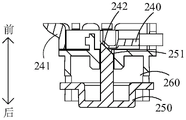
图1为本申请一实施例中的厨房电器的结构示意图(机体为切菜机);图2为本申请另一实施例中的厨房电器的结构示意图(机体为搅拌器);图3为本申请又一实施例中的厨房电器的结构示意图(机体为手持料理机);图4为本申请一实施例中的电池包的结构示意图。Fig. 1 is a schematic structural view of a kitchen appliance in one embodiment of the present application (the body is a vegetable cutter); Fig. 2 is a schematic structural view of a kitchen appliance in another embodiment of the present application (the body is a mixer); A schematic structural view of a kitchen appliance in another embodiment of the application (the body is a hand-held cooking machine); FIG. 4 is a schematic structural view of a battery pack in an embodiment of the present application.
参阅图1至图4,本实用新型一实施例提供的厨房电器包括机体与电池包100,机体的内部设有安装腔,安装腔具有位于机体的表面的安装口。电池包100可拆卸连接于机体。电池包100具有安装状态与拆卸状态,拆卸状态下,电池包100能够经安装口移入或移出安装腔,且电池包100与机体分离后,安装腔外露于机体的表面;安装状态下,电池包100安装于安装腔内,且电池包100的一端经安装口外露。其中,图1中机体为切菜机200,安装腔为第一安装腔211,安装口为第一安装口;图2中机体为搅拌器300,安装腔为第二安装腔340,安装口为第二安装口;图3中机体为手持料理机400,安装腔为第三安装腔411,安装口为第三安装口。Referring to Fig. 1 to Fig. 4, a kitchen appliance provided by an embodiment of the present invention includes a body and a
本申请中,电池包100与机体可拆卸连接,因此,若电池包100电量不足,用户可以将电池包100拆下,并更换满电的电池包100,以增强厨房电器的续航能力;并且由于电池包100可拆卸,使得电池包100具有适配于不同类型机体的可能,通用性较高,例如,电池包100可以安装于图1所示的切菜机200,或者图2所示的搅拌器300,或者图3所示的手持料理机400。在拆卸状态下,电池包100与机体分离后,安装腔外露于机体的表面,安装状态下,电池包100的一端经安装口外露,可见电池包100安装至机体后,其靠近安装口的一端并未安装额外的盖体等部件进行遮挡,这使得厨房电器整体结构更加简单,拆装电池包100时也省去了拆装盖体这一步骤,需要更换电池包100时操作更加方便,也进一步保证了通过更换电池包100提高续航能力这一操作能够顺利进行。In this application, the
具体地,机体可以为前述的切菜机200、搅拌器300或手持料理机400,还可以为榨汁机或绞肉机等。电池包100可以安装于上述任意一种机体内,即多种机体可以共用一个电池包100,通用性较高。电池包100安装于上述各类机体上的位置不同,具体位置在后续实施例中展开介绍。Specifically, the machine body may be the
在一些实施例中,机体包括第一卡接部,电池包100包括第二卡接部;安装状态下,第一卡接部卡接于第二卡接部。具体地,第一卡接部与第二卡接部中,其中一个为凸块,另一个为凹槽或卡钩,通过凸块卡入凹槽或卡钩实现电池包100与机体间的位置锁定;或者,第一卡接部与第二卡接部中,两者均为凸块,通过两个凸块的相互卡合实现电池包100与机体间的位置锁定。第一卡接部与第二卡接部的具体结构不做限制,常见的卡接结构均可应用于本申请中。In some embodiments, the body includes a first engaging portion, and the
参阅图4,进一步地,在一些实施例中,电池包100包括多个第二卡接部,多个第二卡接部分别用于适配不同类型的机体中的第一卡接部。各类机体的形状尺寸不同,电池包100安装于各类机体的位置也相应存在差异,各类机体中设置的第一卡接部的位置也存在差异。因此,在电池包100上设置多个第二卡接部,使其能够适配不同机体上的第一卡接部,从而实现多种机体能够共用一个电池包100。Referring to FIG. 4 , further, in some embodiments, the
继续参阅图4,进一步地,在一些实施例中,以电池包100经安装口移入安装腔的方向为安装方向,多个第二卡接部沿安装方向间隔设置于电池包100的侧壁。具体地,电池包100以附图所示的从后朝前的方向移入机体上的安装腔内以实现安装,即安装方向为从后朝前的方向;电池包100以从前朝后的方向移出机体上的安装腔以实现拆卸。附图所示实施例中,第二卡接部设置为凸块的形式,电池包100包括沿安装方向间隔设置的第一凸块125与第二凸块126。第一凸块125与第二凸块126均位于电池包100的外侧壁上。当然,在其他实施例中,第一凸块125与第二凸块126也可以设置于电池包100上其他位置,例如设置于前端壁。在其他实施例中,可以设置更多数量的凸块,例如,设置三个或四个,每个凸块用于与一类或多类机体中的第一卡接部卡接。Continuing to refer to FIG. 4 , further, in some embodiments, the direction in which the
在另一些实施例中,电池包100与机体也可以通过磁吸固定或螺纹紧固件固定等方式实现可拆卸连接。当然,其他常见的可拆卸连接结构亦可。In some other embodiments, the
图8为图1中厨房电器内电机与电池包的位置分布图(俯视)。FIG. 8 is a position distribution diagram (top view) of the motor and the battery pack in the kitchen appliance in FIG. 1 .
参阅图1、图4与图8,在一些实施例中,机体为切菜机200、榨汁机或绞肉机,机体包括底座210与第一机身220,第一机身220可拆卸连接于底座210,底座210内安装有电机230,第一机身220包括工作腔,工作腔内安装有切割件,切割件用于在电机230驱动下转动以进行切割。第一安装腔211位于底座210内,第一安装口位于底座210的底面。具体地,电池包100安装于第一安装腔211后,可以为电机230供电,以使其能够驱动切割件转动。图1所示实施例中,切菜机200在使用状态下,以第一机身220位于底座210上方的视角放置,安装方向(从后朝前的方向)即为从下朝上的方向,电池包100在安装方向上的尺寸最大。第一安装腔211自底座210的底面朝上延伸,第一安装腔211的底端形成第一安装口。电池包100能够从下朝上移入第一安装腔211以实现安装,并能够从上朝下移出第一安装腔211以实现拆卸。榨汁机或绞肉机的结构与切菜机200类似,此处不再赘述。Referring to Fig. 1, Fig. 4 and Fig. 8, in some embodiments, the body is a
本实施例中,由于电池包100经底座210底面的第一安装口装入第一安装腔211,厨房电器在使用状态下,第一安装口朝向用于承载厨房电器的承载面,电池包100安装到位后,厨房电器在使用过程中,第一安装口以及经第一安装口装入的电池包100不会外露,安全性与美观性更高,也因此无需另外设置盖体来遮蔽电池包100,成本有所降低,同时能降低结构复杂度,更换电池包100时操作也更简单。并且,由于电池包100在安装方向上的尺寸最大,安装方向平行于底座210的轴向,电池包100所需占用底座210的径向尺寸较小,无需为了容纳电池包100而将底座210的径向尺寸设计的过大,有利于该厨房电器的小型化设计,使得该厨房电器对应放置空间的要求较低。In this embodiment, since the
参阅图1与图4,进一步地,在一些实施例中,前述的两个第二卡接部沿安装方向间隔设置于电池包100的侧壁,两个第二卡接部中,在安装方向上位于后端的一个用于适配切菜机200、榨汁机或绞肉机中的第一卡接部。具体地,第一凸块125与第二凸块126沿安装方向间隔设置于电池包100的侧壁,其中,第一凸块125用于适配切菜机200、榨汁机或绞肉机中的第一卡接部。Referring to FIG. 1 and FIG. 4 , further, in some embodiments, the aforementioned two second clamping parts are arranged at intervals along the side wall of the
图13为本实用新型一实施例中电池包与切菜机中锁定结构的示意图;图14为图13中电池包与切菜机中锁定结构另一角度的示意图;图15为图13中切菜机中锁定结构的剖视图。Fig. 13 is a schematic diagram of the locking structure between the battery pack and the vegetable cutter in an embodiment of the present invention; Fig. 14 is a schematic diagram of another angle of the locking structure between the battery pack and the vegetable cutting machine in Fig. 13; Fig. 15 is a schematic diagram of the locking structure in Fig. Sectional view of the locking structure in the vegetable machine.
参阅图13至图15,在一些实施例中,机体为切菜机200时,第一卡接部为卡接块241,通过卡接块241与第一凸块125卡接以实现电池包100与切菜机200的拆装。Referring to FIG. 13 to FIG. 15 , in some embodiments, when the body is a
参阅图1、图13至图15,在一些实施例中,切菜机200包括第一锁定件240、按钮250与第一弹性件,按钮250经底座210的底面外露,按钮250包括第一斜面251,第一锁定件240包括第二斜面242。第一弹性件抵持于第一锁定件240,以使第二斜面242与第一斜面251贴合,第一弹性件被配置为通过自身弹性力推动两个第二卡接部中在安装方向上位于后端的一个与第一卡接部相对靠近,具体地,即推动卡接块241与第一凸块125相对靠近。按钮250能够朝第一锁定件240移动,以使第一斜面251通过抵持于第二斜面242而推动两个第二卡接部中在安装方向上位于后端的一个与第一卡接部相对远离,具体地,即推动卡接块241与第一凸块125相对远离,其中,卡接块241与第一凸块125相对远离的方向和按钮250的移动方向垂直。1, 13 to 15, in some embodiments, the
具体地,在图13与图15视角下,卡接块241位于第一锁定件240的左端,第一凸块125位于电池包壳210中位于右侧的外侧壁上。按钮250经底座210的底面外露,第二斜面242与第一斜面251的形状尺寸匹配,以使二者能够贴合。第一弹性件的一端连接于第一锁定件240,另一端直接或间接连接于底座210。第一弹性件的位置不做限定,只要其能通过自身弹性力抵持第一锁定件240,使其具有靠近电池包100的运动趋势,同时,还需满足第一弹性件能通过自身弹性力抵持第一锁定件240,使其上设置的第二斜面242具有朝第一斜面251运动以实现贴合的趋势。朝上按动按钮250时,第一斜面251将会抵持于第二斜面242,从而推动第一锁定件240朝远离第一凸块125的方向(即朝右)移动,从而使卡接块241与第一凸块125分离实现解锁。松开按钮250时,在第一弹性件回弹力驱动下,第一锁定件240朝靠近第一凸块125的方向(即朝左)移动,从而使卡接块241与第一凸块125卡接实现锁定。同时,第一锁定件240朝左移动时,第二斜面242通过抵持于第一斜面251推动按钮250朝下移动复位。本实施例中,通过斜面配合,将按钮250沿竖直方向的移动转换为卡接块241的水平移动,以实现解锁或锁定。该结构使得按钮250得以设置于底座210上,在使用过程中,按钮250不会外露,可以避免工作状态下误触按钮250而导致电池包100脱出断电。Specifically, from the view angles of FIG. 13 and FIG. 15 , the
在一些实施例中,按钮250上下移动的行程为2.5mm,第一锁定件240左右移动的行程为3mm,卡接块241与第一凸块125在第一锁定件240移动方向上的干涉量为2mm。In some embodiments, the stroke of the
继续参阅图13至图15,在一些实施例中,切菜机200包括安装架260,安装架260固定安装于底座210,按钮250与第一锁定件240均滑动连接于安装架260,第一弹性件设置于第一锁定件240与安装架260之间。具体地,安装架260上设有水平延伸的第一滑槽261,第一锁定件240安装于第一滑槽261内。朝上按动按钮250时,第一锁定件240在第一滑槽261内朝右滑动,松开按钮250时,在第一弹性件回弹力驱动下,第一锁定件240在第一滑槽261内朝左滑动。通过第一滑槽261可以对第一锁定件240的滑动进行导向,使其移动更加稳定,同时,还能对第一锁定件240的滑动进行限位,使其具有适当的滑动行程。安装架260上还设有竖直延伸的第二滑槽262,按钮250上用于被按压的主体部分安装于安装架260的内腔中,按钮250上连接于其主体部分侧壁的延伸臂252伸入第二滑槽262。朝上按压按钮250时,延伸臂252在第二滑槽262内朝上滑动,松开按钮250时,在第一弹性件回弹力驱动下,按钮250朝下移动复位,延伸臂252在第二滑槽262内朝下滑动。通过第二滑槽262可以对按钮250的滑动进行导向,使其移动更加稳定。同时,还能对按钮250的滑动进行限位,使其朝上滑动至被第二滑槽262的顶壁阻挡时到达上限位置。13 to 15, in some embodiments, the
参阅图16,在一些实施例中,电池包100具有经第一安装口伸入第一安装腔211的第一深度与第二深度,第二深度大于第一深度。电池包100经第一安装口伸入至第一深度时,电池包100处于安装状态;电池包100自第一深度移动至第二深度时,所电池包100切换至拆卸状态。具体地,电池包100未安装时,将电池包100朝上推入第一安装腔211内,推动至第一深度后,电池包100将会自动实现锁定,切换至安装状态。安装状态下,继续将电池包100朝上推动,推动至第二深度后,电池包100将会切换至拆卸状态,能够朝下退出第一安装腔211。Referring to FIG. 16 , in some embodiments, the
参阅图16与图17,在一些实施例中,切菜机200包括第二锁定件270与限位件290,拆卸状态下,电池包100被配置为朝第一安装腔211内移动并推动第二锁定件270同步移动,直至电池包100与第二锁定件270卡接固定,且第二锁定件270被限位件290限位以维持安装状态;安装状态下,电池包100被配置为朝第一安装腔211内继续移动并推动第二锁定件270同步移动,以使第二锁定件270脱离限位件290的限位,从而使电池包100与第二锁定件270分离。具体地,电池包100未安装时,将电池包100朝上推入第一安装腔211内,第二锁定件270随之同步移动,电池包100被推动至一定位置后,第二锁定件270将电池包100位置锁定,同时,第二锁定件270被限位件290限定在当前位置,以维持对电池包100的锁定。安装状态下,继续将电池包100朝上推动,第二锁定件270随之同步移动,推动至一定位置后,第二锁定件270与限位件290分离,电池包100与第二锁定件270能够反向移动,移动至一定位置时,电池包100与第二锁定件270分离,从而实现解锁。16 and 17, in some embodiments, the
参阅图16至图19,具体地,在一些实施例中,切菜机200包括安装套280,限位件290连接于安装套280,安装套280内部设有第三滑槽281,第二锁定件270伸入第三滑槽281中,且第二锁定件270与安装套280之间设有第二弹性件2100,第二锁定件270上设有限位部276,电池包100包括锁块140。拆卸状态下,按压电池包100时,第二锁定件270在锁块140抵持下沿安装方向滑入第三滑槽281,并在第三滑槽281限位下逐渐收拢,停止按压电池包100时,第二锁定件270在第二弹性件2100驱动下沿安装方向的反向滑出第三滑槽281,限位件290锁定限位部276时,第二锁定件270抱紧锁块140,即完成了电池包100的安装。安装状态下,按压电池包100时,第二锁定件270在锁块140抵持下沿安装方向滑入第三滑槽281,以使限位件290与限位部276分离,停止按压电池包100时,第二锁定件270在第二弹性件2100驱动下沿第安装方向的反向滑出第三滑槽281并逐渐张开,不再抱紧锁块140,直至第二锁定件270与锁块140分离,即完成了电池包100的拆卸。16 to 19, specifically, in some embodiments, the
参阅图17至图23,具体地,安装套280固定安装于底座210,且伸入第一安装腔211内。第二锁定件270包括第三卡接部271与第四卡接部272,第三卡接部271与第四卡接部272之间限定出卡槽273。锁块140与电池包100的顶端连接。第三卡接部271与第四卡接部272采用具有一定弹性的材质制成,当第三卡接部271与第四卡接部272位于安装套280的第三滑槽281之外时,处于张开状态,形成的卡槽273的尺寸远大于锁块140,无法将锁块140卡死。朝上按压电池包100,锁块140将会抵持于卡槽273的槽壁,使第二锁定件270朝上滑入第三滑槽281,第三卡接部271与第四卡接部272将会在第三滑槽281的限位作用下逐渐收拢,使卡槽273逐渐抱紧锁块140,从而将电池包100与第二锁定件270固定连接。当第二锁定件270朝下滑动,滑动至第三卡接部271与第四卡接部272脱离第三滑槽281时,第三卡接部271与第四卡接部272不再被第三滑槽281限位,将会在自身回弹力作用下张开复位,从而解除对电池包100的锁定。优选的,沿安装方向,第三卡接部271与第四卡接部272的宽度逐渐减小,如此,可以使第三卡接部271与第四卡接部272二者与第二锁定件270的主体部分的连接处的宽度较小,有利于第三卡接部271与第四卡接部272张开与收拢。Referring to FIG. 17 to FIG. 23 , specifically, the
如上所述,第三卡接部271与第四卡接部272在第三滑槽281的限位作用下逐渐收拢,使卡槽273逐渐抱紧锁块140,从而将电池包100与第二锁定件270固定连接。在该过程中,除了卡槽273抱紧锁块140,还需要对第二锁定件270进行限位,使其保持在当前位置,不会退出第三滑槽281。如前所述,通过限位件290对第二锁定件270的限位部276进行限位。具体的,在一些实施例中,第二锁定件270上设有相互连通的第一限位槽274与第二限位槽275,第一限位槽274与第二限位槽275围绕限位部276设置,安装电池包100时,限位件290在第一限位槽274内运动;拆卸电池包100时,限位件290在第二限位槽275内运动。具体地,第一限位槽274的入口处与第二限位槽275的出口处连通,第一限位槽274的出口处与第二限位槽275的入口处连通。安装电池包100时,限位件290在第一限位槽274内运动,直至限位部276被限位件290锁定,第二锁定件270被固定于当前位置。拆卸电池包100时,限位件290在第二限位槽275内运动,限位部276与限位件290间的锁定解除,第二锁定件270在第二弹性件2100驱动下退出第三滑槽281。如此,限位件290在安装与拆卸时的运动路径不同,可以使安装与拆卸相互独立,能更加稳定的进行。As mentioned above, the third
进一步的,在一些实施例中,上述的限位部276呈“V”形,以形成锁定槽2762,限位部276上设有第一限位面2761,电池包100处于未安装状态下(图20所示状态),按压电池包100时,限位件290将会贴合于第一限位面2761沿安装方向的反向相对运动,直至超出第一限位面2761的端部。停止按压电池包100,在第二弹性件2100驱动下,限位件290将会沿安装方向相对运动并卡于锁定槽2762内(图21所示状态),以完成对第二锁定件270的限位。当然,限位部276也可以为“U”形,或其他类似形状。设置为此类形状后,可以使限位件290在卡入锁定槽2762后不易与锁定槽2762分离,稳定性更好。第二限位槽275还包括第二限位面2751,电池包100处于安装状态下(图22所示状态),按压电池包100时,限位件290将会沿安装方向的反向相对运动,与锁定槽2762分离,解除对第二锁定件270的限位。接着,限位件290会抵持于第二限位面2751,沿安装方向的反向贴合于第二限位面2751相对运动。停止按压电池包100,在第二弹性件2100驱动下,限位件290将会沿安装方向相对运动并到达第二限位槽275的出口处(图23所示状态)。Further, in some embodiments, the above-mentioned limiting
需要说明的是,前述过程中,采用了限位件290相对第二锁定件270运动的描述方式。实际上,绝对移动的部件为第二锁定件270。但限位件290需要能进行摆动,以适应第一限位槽274与第二限位槽275宽度方向(图19视角下的水平方向)上的路径变化。It should be noted that, in the foregoing process, a description method of movement of the limiting
参阅图17与图18,具体的,在一些实施例中,限位件290为弹性杆,包括主体段291与自由端292,二者一体连接。主体段291与安装套280的槽壁固定连接。自由端292相对于主体段291弯折,通过自由端292卡于锁定槽2762,以实现对第二锁定件270的限位。弹性杆自身具有一定的弹性,在图20至图21的运动过程中,自由端292沿第一限位面2761在安装方向的反向相对运动至超出第一限位面2761的端部时,停止按压电池包100,在第二弹性件2100驱动下,自由端292将会沿安装方向相对运动,在弹性杆弹性力作用下,自由端292会朝右摆动,从而卡于锁定槽2762内。在图22至图23的运动过程中,自由端292抵持于第二限位面2751相对运动时,停止按压电池包100,在第二弹性件2100驱动下,自由端292将会沿安装方向相对运动,在弹性杆弹性力作用下,自由端292会朝左摆动,从而沿第二限位槽275滑动并到达第二限位槽275的出口。当然,除了使用弹性杆作为限位件290,其他类似的能够进行摆动的材质亦可,例如,也可以选用钢丝绳作为限位件290。Referring to FIG. 17 and FIG. 18 , specifically, in some embodiments, the limiting
在上述过程中,可以通过按压电池包100时的手感来判断自由端292当前的位置状态。例如,在图20至图21的运动过程中,自由端292沿第一限位面2761在安装方向的反向相对运动时,会与第一限位面2761产生刮擦,按压时能够感受到一定的阻力。当自由端292超出第一限位面2761的端部时,不再刮擦第一限位面2761,阻力感减小甚至消失,此时即可松开电池包100。在图22至图23的运动过程中,自由端292与锁定槽2762分离,当自由端292抵持于第二限位面2751相对运动时,会与第二限位面2751产生刮擦,按压时能够感受到一定的阻力,此时即可松开电池包100。During the above process, the current position of the
参阅图22,在一些实施例中,弹性杆的自由端292卡于锁定槽2762时,第二限位面2751的始端位于限位件290靠近第一限位槽274的一侧。即图22视角下,第二限位面2751的始端位于自由端292的左侧,二者之间间距为a。如此,当电池包100处于安装状态下(图22所示状态),按压电池包100时,可以保证自由端292沿安装方向的反向相对运动时,能顺利的抵持于第二限位面2751,在第二限位槽275内相对运动,进而顺利完成对电池包100的拆卸。若自由端292为圆柱状,其半径为b,优选的,a>1.5b,以免自由端292再次回到第一限位槽274,并再次卡于锁定槽2762。Referring to FIG. 22 , in some embodiments, when the
参阅图18,在一些实施例中,弹性杆具有两个自由端292,第二锁定件270的正面与背面均设有一组前述的限位部276、第一限位槽274与第二限位槽275,每组与一个自由端292配合进行限位。如此,可以更稳定的对第二锁定件270进行限位。Referring to Fig. 18, in some embodiments, the elastic rod has two
参阅图17,在一些实施例中,第二锁定件270上设有容纳槽277,第二弹性件2100设置于容纳槽277内,第二弹性件2100的一端与容纳槽277的槽壁固定连接,另一端与第三滑槽281的固定连接抵持。当第二锁定件270在第二弹性件2100回弹力驱动下朝外弹出时,由于第二弹性件2100固定连接于容纳槽277的槽壁,可以防止第二弹性件2100完全脱出第三滑槽281。还可以在容纳槽277内设置导向柱,将第二弹性件2100套设于导向柱上,对第二弹性件2100进行导向。Referring to FIG. 17 , in some embodiments, the
参阅图1与图8,在一些实施例中,底座210、电机230与电池包100沿安装方向的投影外轮廓均为圆形或类圆形,电机230位于工作腔内沿底座210径向的中心位置;底座210的半径为R,电池包100的直径为d,电机230的半径为r,R=K(d+r),其中1≤K≤1.2。具体地,类圆形可以是近似圆形的形状,例如多边形或椭圆形等。在垂直于安装方向的平面内,电机230的投影位于底座210投影的中心位置。电机230与电池包100在电机230输出轴的轴线上错开设置,即电池包100沿底座210的径向位于电机230的外侧。当满足K=1时,即R=d+r时,底座210的径向尺寸可以取到最小值,有利于该厨房电器的小型化设计,使得该厨房电器对应放置空间的要求较低。Referring to FIG. 1 and FIG. 8, in some embodiments, the projected outer contours of the
图9为图1中厨房电器内电机与电池包的位置分布图(俯视)。FIG. 9 is a position distribution diagram (top view) of the motor and the battery pack in the kitchen appliance in FIG. 1 .
参阅图1与图9,在一些实施例中,安装状态下,在垂直于安装方向的平面内,电池包100的中心的投影为第一位置A,电机230的中心的投影为第二位置B,厨房电器的重心的投影为第三位置C,第三位置C经过第一位置A与第二位置B的连线。当电池包100与电机230的安装位置的投影满足上述条件时,可以使电池包100的重量与电机230的重量较好的平衡,使得整个厨房电器在安装完成后稳定性更好,不易发生晃动或倾倒。1 and 9, in some embodiments, in the installed state, in a plane perpendicular to the installation direction, the projection of the center of the
继续参阅图1与图9,优选地,在一些实施例中,第二位置B与第三位置C的间距为s,电池包100的重量为m,0.024≤s/m≤0.032。当满足上述范围时,可以进一步使电池包100的重量与电机230的重量得到较好的平衡,整个厨房电器在安装完成后稳定性更好,不易发生晃动或倾倒。具体地,在一些实施例中,电池包100的重量m为100g,厨房电器未安装电池包100之前的重量范围为1100g-1500g。第二位置B与第三位置C的间距s的范围为4.89mm-6.39mm。优选地,第一位置A与第二位置B的间距的范围为40mm-45mm。Continue referring to FIG. 1 and FIG. 9 , preferably, in some embodiments, the distance between the second position B and the third position C is s, the weight of the
参阅图2,在一些实施例中,机体为搅拌器300,搅拌器300包括第二机身310、手柄320,以及能够通过电机驱动进行搅拌的搅拌头330,第二机身310的一侧连接于手柄320,另一侧连接于搅拌头330,且手柄320的延伸方向与第二机身310的延伸方向基本平行,搅拌头330的延伸方向与第二机身310的延伸方向基本垂直;第二安装口位于手柄320上背离搅拌头330的侧壁,第二安装腔340自手柄320内部延伸至第二机身310内部。具体地,基本垂直是指夹角范围为80度-90度,基本平行是指夹角不超过10度。手柄320、第二机身310与搅拌头330沿安装方向排布,手柄320连接于第二机身310的后侧,搅拌头330连接于第二机身310的前侧。第二安装口位于手柄320的后侧壁。第二安装腔340沿安装方向自手柄320内部延伸至第二机身310内部,电池包100安装到位后,部分位于手柄320内,部分位于第二机身310内。Referring to Fig. 2, in some embodiments, the body is a
参阅图2与图4,进一步地,在一些实施例中,两个第二卡接部沿安装方向间隔设置于电池包100的侧壁,两个第二卡接部中,在安装方向上位于前端的一个用于适配搅拌器300中的第一卡接部。具体地,第一凸块125与第二凸块126沿安装方向间隔设置于电池包100的侧壁,其中,第二凸块126用于适配搅拌器300中的第一卡接部。当然,在其他实施例中,也可以在设计时调整搅拌器300中的第一卡接部的位置,使得第一凸块125用于适配搅拌器300中的第一卡接部。Referring to FIG. 2 and FIG. 4 , further, in some embodiments, two second clamping parts are arranged at intervals along the side wall of the
继续参阅图2与图4,在一些实施例中,手柄320与第二机身310之间通过连接部350连接,连接部350的延伸方向与第二机身310的延伸方向基本垂直,第二安装腔340至少分布于手柄320与连接部350。电池包100的径向尺寸与连接部350沿电池包100径向的尺寸的比值范围为0.63-0.96,电池包100的轴向尺寸与手柄320、连接部350、第二机身310三者沿电池包100轴向的尺寸之和的比值范围为0.5-0.7。具体地,手柄320、连接部350、第二机身310与搅拌头330沿安装方向排布,手柄320通过连接部350连接于第二机身310的后侧。第二安装腔340自手柄320的后侧壁经过连接部350朝前延伸至第二机身310内部,即在安装方向上,第二安装腔340中部分位于手柄320,部分位于连接部350,部分位于第二机身310。电池包100的轴向平行于安装方向,电池包100的径向尺寸是指垂直于其安装方向的尺寸。当按照前述实施例所述的方式设置第二安装腔340时,可以尽量减小连接部350在电池包100径向的尺寸,使结构更加紧凑。同时,能够较好的利用手柄320、连接部350、第二机身310三者沿电池包100轴向的内部空间,亦能使结构更加紧凑。Continuing to refer to FIG. 2 and FIG. 4 , in some embodiments, the
参阅图3,在一些实施例中,机体为手持料理机400,手持料理机400包括第三机身410,以及能够通过电机驱动进行研磨破碎的研磨头420;第三安装腔411位于第三机身410内部,第三机身410在自身延伸方向上的一端连接于研磨头420,另一端设有第三安装口。具体地,手持料理机400整体呈圆柱状或类圆柱状。第三机身410与研磨头420沿安装方向排布,研磨头420连接于第三机身410的前端。第三机身410的后端壁设有第三安装口,第三安装腔411自第三机身410的后端壁朝前延伸。Referring to Fig. 3, in some embodiments, the body is a hand-held
参阅图3与图4,进一步地,在一些实施例中,两个第二卡接部沿安装方向间隔设置于电池包100的侧壁,两个第二卡接部中,在安装方向上位于前端的一个用于适配手持料理机400中的第一卡接部。具体地,第一凸块125与第二凸块126沿安装方向间隔设置于电池包100的侧壁,其中,第二凸块126用于适配手持料理机400中的第一卡接部。Referring to FIG. 3 and FIG. 4 , further, in some embodiments, two second clamping parts are arranged at intervals along the side wall of the
参阅图3与图4,在一些实施例中,电池包100的径向尺寸与第三机身410沿电池包100径向的尺寸的比值范围为0.62-0.95,电池包100的轴向尺寸与第三机身410沿电池包100轴向的尺寸的比值范围为0.1-0.3。具体地,电池包100的轴向平行于安装方向以及第三机身410的轴向,电池包100的径向是指垂直于其安装方向的方向,第三机身410的径向是指垂直于其轴向的方向。相较于安装方向垂直于第三机身410轴向的安装方式,当按照图3所示方式设置第三安装腔411并安装电池包100时,由于第三机身410在自身轴向的尺寸较大,使电池包100以该方向进行安装可以充分利用第三机身410的内部空间,尽量减小第三机身410的径向尺寸,有利于实现装置的小型化,且更便于用户握持。3 and 4, in some embodiments, the ratio of the radial dimension of the
图5为图4中电池包另一角度的结构示意图。FIG. 5 is a structural schematic diagram of another angle of the battery pack in FIG. 4 .
参阅图4与图5,在一些实施例中,电池包100包括用于显示剩余电量的显示屏,以电池包100经安装口移入安装腔的方向为安装方向,显示屏位于电池包100上沿安装方向的后端。在电池包100安装于机体后,电池包100的后端经安装口外露,从而使其后端设置的显示屏能够直接经安装口露出,用户无需拆下电池包100就能直接观察到电池包100的电量。同时,由于显示屏150经安装口外露,用户可以及时获知电池包100当前电量,以便于及时将电量不足的电池包100拆下后更换满电的电池包100,不易出现将厨房电器携带外出后进行使用时才发现电量不足的情况。此外,由于用户可以及时获知电池包100当前电量,能够及时将电量不足的电池包100拆下后更换满电的电池包100,使得厨房电器的电池包100一直处于电量较为充足的状态,在需要将厨房电器携带外出时,能够随拿随走,在时间较为紧急时,无需耽误时间检查电量是否充足以及在检查得知电量不足后更换电池包100。当然,在其他实施例中,显示屏也可以自电池包100的侧壁沿电池包100的径向朝外凸伸。电池包100沿安装方向的投影轮廓呈圆形或类圆形,其径向即为垂直于安装方向的方向。Referring to FIG. 4 and FIG. 5 , in some embodiments, the
参阅图4与图5,在一些实施例中,以电池包100经安装口移入安装腔的方向为安装方向,电池包100上沿安装方向的后端凸出于机体的表面或者与机体的表面平齐。具体地,在图2所示实施例中,电池包100上沿安装方向的后端凸出于搅拌器300中手柄320的后侧壁,以便于用户观察其电量。类似地,在图3所示实施例中,电池包100上沿安装方向的后端凸出于手持料理机400中第三机身410的后端壁。但在图1所示实施例中,电池包100上沿安装方向的后端不能超出切菜机200中底座210的底面,以免影响切菜机200放置于承载面。优选地,电池包100上沿安装方向的后端可以与切菜机200中底座210的底面平齐。使得电池包100也被承载面支撑,以将电池包100托起。若切菜机200中的第一卡接部失效,由于电池包100被承载面支撑,可以使电池包100依然位于第一安装腔211内不会脱出。Referring to Fig. 4 and Fig. 5, in some embodiments, the direction in which the
在上述实施例中,显示屏位于电池包100上沿安装方向的后端,在另一些实施例中,显示屏还可以设置于机体。具体地,显示屏安装于机体,且其屏幕外露于机体的表面。当电池包100安装于机体并实现电连接后,显示屏可以显示电池包100的剩余电量。当电池包100从机体上拆下后,显示屏显示电池包100处于未安装状态。In the above embodiments, the display screen is located at the rear end of the
参阅图1至图4,在一些实施例中,以电池包100经安装口移入安装腔的方向为安装方向,安装腔沿安装方向的投影轮廓与电池包100沿安装方向的投影外轮廓重合。具体地,安装腔在电池包100的径向上的最大尺寸与电池包100的径向上的最大尺寸相等。如此,在电池包100装入安装腔后,电池包100的侧壁上至少部分区域能够与安装腔的腔壁贴合,灰尘与液体不易经电池包100与安装腔的腔壁之间进入安装腔,从而能增强防水防尘性。Referring to FIG. 1 to FIG. 4 , in some embodiments, the direction in which the
图10为图4中电池包的爆炸图。FIG. 10 is an exploded view of the battery pack in FIG. 4 .
参阅图4、图5与图10,进一步地,在一些实施例中,电池包100包括贴合部,贴合部位于电池包100的侧壁上沿安装方向的至少部分区域,安装状态下,贴合部与安装腔的腔壁贴合。具体地,电池包100的外侧壁上部分区域沿电池包100的径向朝外凸伸,从而形成贴合部。沿电池包100的径向,贴合部的尺寸与安装腔的尺寸基本相等。进一步地,电池包100的外侧壁上靠近后端的区域沿电池包100的径向朝外凸伸,从而形成贴合部。如此,可以在靠近安装口处将安装腔封堵,使灰尘与液体基本上完全无法进入安装腔内,防水防尘性更好。Referring to FIG. 4, FIG. 5 and FIG. 10, further, in some embodiments, the
图6为图4本申请一实施例中的电池包的正视图;图7为图4本申请一实施例中的电池包的俯视图。FIG. 6 is a front view of the battery pack in an embodiment of the present application in FIG. 4 ; FIG. 7 is a top view of the battery pack in an embodiment of the present application in FIG. 4 .
参阅图4、图5与图10,在一些实施例中,电池包100包括壳体以及设于壳体内的三个电池单体130,以电池包100经安装口移入安装腔的方向为安装方向,三个电池单体130沿安装方向的投影的中心连线形成三角形。三个电池单体130呈三角形分布,可以使其在电池包100径向上分布更加紧凑,从而使电池包100径向尺寸更小,从而使图1所示的切菜机200中底座210的径向尺寸较小,图3所示的手持料理机400的第三机身410的径向尺寸较小。参阅图5至图7,电池包100为圆柱状或类圆柱状,其径向为垂直于安装方向的方向。当三个电池单体130沿安装方向的投影的中心连线形成三角形时,电池包100的径向尺寸范围为38mm-55mm。优选地,整个电池包100的长度L4为47mm,宽度L3为42mm,高度L1+L2的总和为96mm,壳体壁厚为1.5mm。Referring to Fig. 4, Fig. 5 and Fig. 10, in some embodiments, the
可以理解地,在一些实施例中,三个电池单体130沿安装方向的投影的中心连线形成正三角形,此时三个电池单体130在电池包100径向上分布更加紧凑,电池包100径向尺寸更小。It can be understood that, in some embodiments, the central lines of the projections of the three
图11为图4中电池包的第二壳部的结构示意图。FIG. 11 is a schematic structural diagram of the second casing of the battery pack in FIG. 4 .
参阅图4、图10与图11,在一些实施例中,壳体包括沿安装方向依次排布的第一壳部110与第二壳部120,第一壳部110内安装有线路板,第二壳部120内安装有电池单体130。参阅图6,第一壳部110沿安装方向的尺寸为L1,第二壳部120沿安装方向的尺寸为L2,0.2≤L1/L2≤0.4。第一壳部110与第二壳部120沿安装方向的尺寸比满足上述条件时,可以在具有足够空间安装电池单体130与线路板的前提下使整个电池包100沿安装方向的尺寸较小。Referring to Figure 4, Figure 10 and Figure 11, in some embodiments, the housing includes a
具体地,第一壳部110与第二壳部120可拆卸连接。第二壳部120的外侧壁上靠近第一壳部110的区域朝外凸伸以形成凸环124,凸环124的外侧壁的径向尺寸与第一壳部110的外侧壁的径向尺寸相等。凸环124的外侧壁与第一壳部110的外侧壁共同形成前述的贴合部。Specifically, the
参阅图4、图10与图11,在一些实施例中,第一壳部110与第二壳部120通过螺纹紧固件连接;以及/或者,第一壳部110与第二壳部120卡接。具体地,第一壳部110与第二壳部120可以通过螺钉等螺纹紧固件连接。或者,第一壳部110与第二壳部120通过卡接实现固定安装。或者,第一壳部110与第二壳部120同时通过上述两种方式实现固定安装。Referring to FIG. 4, FIG. 10 and FIG. 11, in some embodiments, the
参阅图4、图10与图11,具体地,在一些实施例中,第一壳部110上设有多个沿电池包100的周向间隔排布的卡钩111,第二壳部120上设有多个沿电池包100的周向间隔排布的卡块121,多个卡块121一一对应的卡入多个卡钩111;以及,第一壳部110上设有多个沿电池包100的周向间隔排布的连接柱112,连接柱112伸入第二壳部120且与第二壳部120通过螺纹紧固件连接。Referring to FIG. 4 , FIG. 10 and FIG. 11 , specifically, in some embodiments, the
具体地,第一壳部110上设有三个沿电池包100的周向间隔排布的卡钩111,对应地,第二壳部120上设有三个沿电池包100的周向间隔排布的卡块121,每一个卡块121对应的卡入一个卡钩111。同时,第一壳部110上设有两个沿电池包100的周向间隔排布的连接柱112,对应地,第二壳部120上设有两个沿电池包100的周向间隔排布的连接套122,每一个连接柱112对应的伸入一个连接套122内,且通过螺钉连接。本实施例中,同时通过卡接与螺纹紧固件连接的方式实现第一壳部110与第二壳部120的固定安装,可以提高二者安装牢固性。Specifically, the
参阅图4、图10与图11,在一些实施例中,第二壳部120沿安装方向的前端设有母端子,机体上设有公端子,母端子与公端子插接以实现电池包100与机体的电连接。具体地,母端子为插槽131,插槽131电连接于电池单体130。第二壳部120的前端面设有通槽123,插槽131经通槽123露出。公端子为设置于机体的插针,插针插入插槽131,以实现二者的电连接,从而实现电池包100与机体的电连接。在另一些实施例中,也可以互换插槽与插针的位置。Referring to Fig. 4, Fig. 10 and Fig. 11, in some embodiments, the front end of the
图12为本申请一实施例中的充电座的结构示意图。FIG. 12 is a schematic structural diagram of a charging stand in an embodiment of the present application.
参阅图12,在一些实施例中,厨房电器包括充电座500,电池包100可拆卸连接于充电座500,与机体分离的电池包100能够连接于充电座500以进行充电。具体地,充电座500上设有充电接口510,电池包100从机体上拆下后,可以通过插接于充电接口510实现与充电座500的电连接,从而实现充电。电池包100可以轮换使用与充电,以提高各类机体的续航能力。Referring to FIG. 12 , in some embodiments, the kitchen appliance includes a charging
以上所述实施例的各技术特征可以进行任意的组合,为使描述简洁,未对上述实施例中的各个技术特征所有可能的组合都进行描述,然而,只要这些技术特征的组合不存在矛盾,都应当认为是本说明书记载的范围。The technical features of the above-mentioned embodiments can be combined arbitrarily. To make the description concise, all possible combinations of the technical features in the above-mentioned embodiments are not described. However, as long as there is no contradiction in the combination of these technical features, should be considered as within the scope of this specification.
以上所述实施例仅表达了本申请的几种实施方式,其描述较为具体和详细,但并不能因此而理解为对本申请范围的限制。应当指出的是,对于本领域的普通技术人员来说,在不脱离本申请构思的前提下,还可以做出若干变形和改进,这些都属于本申请的保护范围。因此,本申请的保护范围应以所附权利要求为准。The above-mentioned embodiments only express several implementation modes of the present application, and the description thereof is relatively specific and detailed, but should not be construed as limiting the scope of the present application. It should be noted that those skilled in the art can make several modifications and improvements without departing from the concept of the present application, and these all belong to the protection scope of the present application. Therefore, the protection scope of the present application should be determined by the appended claims.
Claims (35)
Priority Applications (6)
| Application Number | Priority Date | Filing Date | Title |
|---|---|---|---|
| CN202221198596.7U CN217852603U (en) | 2022-05-18 | 2022-05-18 | Kitchen appliance |
| JP2023579096A JP7629117B2 (en) | 2022-05-18 | 2022-12-05 | Kitchen appliances |
| PCT/CN2022/136549 WO2023221459A1 (en) | 2022-05-18 | 2022-12-05 | Kitchen appliance |
| US18/428,553 US20250222418A1 (en) | 2022-05-18 | 2022-12-05 | Kitchen appliance |
| KR1020247001852A KR20240025607A (en) | 2022-05-18 | 2022-12-05 | kitchen appliances |
| EP22942479.1A EP4527266A1 (en) | 2022-05-18 | 2022-12-05 | Kitchen appliance |
Applications Claiming Priority (1)
| Application Number | Priority Date | Filing Date | Title |
|---|---|---|---|
| CN202221198596.7U CN217852603U (en) | 2022-05-18 | 2022-05-18 | Kitchen appliance |
Publications (1)
| Publication Number | Publication Date |
|---|---|
| CN217852603U true CN217852603U (en) | 2022-11-22 |
Family
ID=84091376
Family Applications (1)
| Application Number | Title | Priority Date | Filing Date |
|---|---|---|---|
| CN202221198596.7U Active CN217852603U (en) | 2022-05-18 | 2022-05-18 | Kitchen appliance |
Country Status (6)
| Country | Link |
|---|---|
| US (1) | US20250222418A1 (en) |
| EP (1) | EP4527266A1 (en) |
| JP (1) | JP7629117B2 (en) |
| KR (1) | KR20240025607A (en) |
| CN (1) | CN217852603U (en) |
| WO (1) | WO2023221459A1 (en) |
Cited By (2)
| Publication number | Priority date | Publication date | Assignee | Title |
|---|---|---|---|---|
| CN116509289A (en) * | 2023-04-27 | 2023-08-01 | 武汉水魔方智能科技有限公司 | Power management unit and cleaner handle |
| WO2023221459A1 (en) * | 2022-05-18 | 2023-11-23 | 莱克电气绿能科技(苏州)有限公司 | Kitchen appliance |
Families Citing this family (1)
| Publication number | Priority date | Publication date | Assignee | Title |
|---|---|---|---|---|
| DE102024114087A1 (en) * | 2024-05-21 | 2025-11-27 | Zwilling J. A. Henckels Aktiengesellschaft | hand mixer |
Family Cites Families (17)
| Publication number | Priority date | Publication date | Assignee | Title |
|---|---|---|---|---|
| CN104037463A (en) | 2014-01-21 | 2014-09-10 | 卢冠熊 | Universal battery pack system |
| JP2016024965A (en) | 2014-07-22 | 2016-02-08 | 八洲電業株式会社 | Battery case unit |
| JP2018065201A (en) | 2016-10-17 | 2018-04-26 | 株式会社マキタ | Electric appliance |
| EP3552721A4 (en) | 2016-12-06 | 2020-08-12 | Positec Power Tools (Suzhou) Co., Ltd | High-pressure cleaning machine and high-pressure cleaning machine assembly |
| US10045650B2 (en) * | 2016-12-31 | 2018-08-14 | Frederic William Brady, JR. | DC rechargeable battery powered appliance purposed to remove a thin outer layer of skin from vegetables and fruits |
| JP7038200B2 (en) | 2018-05-07 | 2022-03-17 | ▲蘇▼州宝▲時▼得▲電▼▲動▼工具有限公司 | Battery pack and power tool unit |
| CN210120407U (en) | 2018-11-19 | 2020-02-28 | 方艳平 | Charging base of handheld wireless charging food processor |
| CN209610780U (en) | 2019-01-24 | 2019-11-12 | 颜平俊 | A kind of rechargeable juice extractor of inner space compact |
| JP7267061B2 (en) | 2019-03-27 | 2023-05-01 | 株式会社トプコン | battery holder |
| CN210576096U (en) | 2019-09-12 | 2020-05-19 | 宁波三叶工具有限公司 | Connecting piece in detachable battery pack assembly |
| CN211066274U (en) * | 2019-11-01 | 2020-07-24 | 广东新宝电器股份有限公司 | Electric food processor |
| CN211324535U (en) | 2019-11-29 | 2020-08-25 | 浙江科技学院 | Electric power-assisted grinder |
| CN113977509A (en) * | 2020-07-27 | 2022-01-28 | 浙江齐享科技有限公司 | Battery pack and electric tool |
| CN112636423A (en) * | 2020-12-16 | 2021-04-09 | 广东长柏电器实业有限公司 | Rechargeable small kitchen appliance with detachable battery |
| CN112545381B (en) * | 2020-12-24 | 2025-04-08 | 珠海格力电器股份有限公司 | Dust collection box and floor sweeping robot |
| CN114204196B (en) * | 2021-12-17 | 2025-09-05 | 深圳市优必选科技股份有限公司 | Quick release mechanism, battery module and electrical equipment |
| CN217852603U (en) * | 2022-05-18 | 2022-11-22 | 莱克电气绿能科技(苏州)有限公司 | Kitchen appliance |
-
2022
- 2022-05-18 CN CN202221198596.7U patent/CN217852603U/en active Active
- 2022-12-05 JP JP2023579096A patent/JP7629117B2/en active Active
- 2022-12-05 KR KR1020247001852A patent/KR20240025607A/en active Pending
- 2022-12-05 EP EP22942479.1A patent/EP4527266A1/en active Pending
- 2022-12-05 WO PCT/CN2022/136549 patent/WO2023221459A1/en not_active Ceased
- 2022-12-05 US US18/428,553 patent/US20250222418A1/en active Pending
Cited By (2)
| Publication number | Priority date | Publication date | Assignee | Title |
|---|---|---|---|---|
| WO2023221459A1 (en) * | 2022-05-18 | 2023-11-23 | 莱克电气绿能科技(苏州)有限公司 | Kitchen appliance |
| CN116509289A (en) * | 2023-04-27 | 2023-08-01 | 武汉水魔方智能科技有限公司 | Power management unit and cleaner handle |
Also Published As
| Publication number | Publication date |
|---|---|
| KR20240025607A (en) | 2024-02-27 |
| US20250222418A1 (en) | 2025-07-10 |
| JP2024526431A (en) | 2024-07-18 |
| JP7629117B2 (en) | 2025-02-12 |
| WO2023221459A1 (en) | 2023-11-23 |
| EP4527266A1 (en) | 2025-03-26 |
Similar Documents
| Publication | Publication Date | Title |
|---|---|---|
| CN217852603U (en) | Kitchen appliance | |
| US4620476A (en) | Multi-purpose kitchen appliance | |
| KR102842171B1 (en) | Food processor and its knife set mounting structure and mixing cup | |
| US20230157476A1 (en) | Kitchen appliance | |
| CN218683927U (en) | Stirring machine | |
| CN218338279U (en) | Kitchen appliance | |
| CN205729017U (en) | A kind of detachable coupled structure and cooking machine thereof | |
| CN212326217U (en) | Retaining member, rotating head, rotating assembly, coupling, container and food processor | |
| CN117617787A (en) | a mixer | |
| CN212368834U (en) | Portable food processor | |
| CN215272292U (en) | Stirring cup assembly and food processor | |
| CN115919132A (en) | Cooking utensil | |
| CN217285520U (en) | Cooking cup and cooking machine | |
| CN218105690U (en) | Shell structure convenient to dismouting | |
| CN103945745A (en) | Food preparation accessory presenting a storage design | |
| EP4176781A1 (en) | Locking component, rotary head, rotary assembly, shaft coupling, container, and food processor | |
| CN218832593U (en) | Food processor | |
| CN218899242U (en) | Food processor | |
| CN207561829U (en) | Cup and cooking machine | |
| CN117122189A (en) | Kitchen Appliances | |
| CN219270736U (en) | Hand-held mixer with chargeable storage base | |
| CN219982657U (en) | Easily abluent stock machine | |
| CN219515891U (en) | Pot lid assembly | |
| CN120643135B (en) | A composite kitchen appliance with a retractable blade structure | |
| CN222237499U (en) | Supplementary food mixer |
Legal Events
| Date | Code | Title | Description |
|---|---|---|---|
| GR01 | Patent grant | ||
| GR01 | Patent grant |