CN2178683Y - Motorcycle main tripod parking positioning device - Google Patents
Motorcycle main tripod parking positioning device Download PDFInfo
- Publication number
- CN2178683Y CN2178683Y CN93247375U CN93247375U CN2178683Y CN 2178683 Y CN2178683 Y CN 2178683Y CN 93247375 U CN93247375 U CN 93247375U CN 93247375 U CN93247375 U CN 93247375U CN 2178683 Y CN2178683 Y CN 2178683Y
- Authority
- CN
- China
- Prior art keywords
- bracket
- motorcycle
- main
- tripod
- rod
- Prior art date
- Legal status (The legal status is an assumption and is not a legal conclusion. Google has not performed a legal analysis and makes no representation as to the accuracy of the status listed.)
- Expired - Fee Related
Links
- 230000000903 blocking effect Effects 0.000 claims abstract description 17
- 230000005484 gravity Effects 0.000 abstract description 4
- 239000006185 dispersion Substances 0.000 abstract 1
- 238000010586 diagram Methods 0.000 description 6
- 230000000694 effects Effects 0.000 description 3
- 230000005540 biological transmission Effects 0.000 description 1
- 238000004519 manufacturing process Methods 0.000 description 1
- 238000005096 rolling process Methods 0.000 description 1
Images


Landscapes
- Automatic Cycles, And Cycles In General (AREA)
Abstract
Description
本实用新型有关于一种摩托车主脚架停车定位装置,特别指一种防止变形的摩托车主脚架停车定位装置。The utility model relates to a parking positioning device for a main tripod of a motorcycle, in particular to a parking positioning device for a main tripod of a motorcycle which prevents deformation.
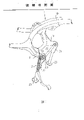
一般摩托车的传动是以其引擎带动后轮转动,以使摩托车可以后轮带动前轮向前进,而在摩托车停车时,为使其后轮悬空并将摩托车车体支撑于地面,以避免摩托车在启动时,其后轮因贴抵于地面而造成摩托车在启动加油时,后轮因急速加油而快速转动,以致摩托车后轮接触地面而冲出,特于摩托车的底端设有一可供停车的定位机构,如图1是习知摩托车主脚架定位机构的侧视图所示,该停车定位机构1是于摩托车车体架10的底端设有一托架11,该托架11位于摩托车车体架10的底端,以使该摩托车车体架10可以托架11为支点,而将摩托车的重心向前移,同时,使前轮可贴地并将后轮撑起离开地面而悬空,且使摩托车在停车时可支撑定位于地面,于托架11上枢设有一主脚架2,该主脚架2的两侧分别形成有一支撑架21,该支撑架21之间固设有一可相互连动的横杆22,且在两支撑架21底端分别形成有一抵靠面23,该抵靠面23于主脚架2支撑后可靠抵地面,而使摩托车在停车之后不致倾倒;此外,一支撑架21的一侧边形成有一抵掣边211,并在托架11对应于支撑架21的抵掣边211形成有一挡块111,当主脚架2的抵靠面23向下抵靠地面,而使摩托车车体架10可以支撑架21的抵靠面23为支撑点,并可使摩托车车体架10向后拉动以使支撑架21的抵掣边211被托架11的挡块111所阻挡而无法前进,进而摩托车车体架10的重心藉由主脚架2的支撑,而能平衡站立于地面。The transmission of a general motorcycle is that its engine drives the rear wheels to rotate, so that the rear wheels can drive the front wheels forward. In order to prevent the rear wheel of the motorcycle from sticking to the ground when the motorcycle is started, the rear wheel will rotate rapidly due to rapid refueling when the motorcycle is started to refuel, so that the rear wheel of the motorcycle will touch the ground and rush out. The bottom end is provided with a positioning mechanism for parking, as shown in Figure 1 is a side view of a known motorcycle main leg positioning mechanism, this
以上所述习知摩托车的主脚架仍有下列缺点:The main tripod of above-mentioned known motorcycle still has following shortcoming:
(1)抵掣边与挡块的抵触面需足以抵抗摩托车的重量,因而需较高硬度的材料,但因该材料不易切割,故在掣造上相当不容易。(1) The contact surface between the stopper edge and the stopper must be strong enough to resist the weight of the motorcycle, so a material with higher hardness is required, but because the material is not easy to cut, it is not easy to make the stopper.
(2)该停车定位机构在使用过一段期间后,常因托架挡块承受摩托车的重量,以致造成托架长时间单边受力而变形,因而在主脚架欲收回时,主脚架内侧面抵触于托架的变形处,而经常发生主脚架不易收回的现象。(2) After the parking positioning mechanism has been used for a period of time, the bracket block often bears the weight of the motorcycle, so that the bracket is deformed by unilateral force for a long time. The inner side of the frame is in conflict with the deformation of the bracket, and it often happens that the main tripod is not easy to retract.
(3)主脚架将摩托车的重量加诸于托架上的挡块,是故,该挡块容易变形,而使主脚架逐渐向前倾,同时使后轮愈离地面愈近,而在摩托车启动时有冲出的顾虑。(3) The main tripod adds the weight of the motorcycle to the stopper on the bracket, so the stopper is easily deformed, and the main tripod gradually tilts forward, and at the same time the rear wheel is closer to the ground, However, there is a concern about rushing out when the motorcycle is started.
因此,本实用新型的主要目的,在于提供一种摩托车主脚架停车定位装置,而能达成避免托架变形的功效。Therefore, the main purpose of the present utility model is to provide a parking positioning device for the main leg of a motorcycle, which can achieve the effect of avoiding deformation of the bracket.
本实用新型的目的是以如下方式达到的:The purpose of this utility model is achieved in the following manner:
一种摩托车主脚架停车定位装置,其包含有一托架,及一枢连于托架上的主脚架,其中,托架两侧的前端分别开设有一穿孔,且在托架的一侧形成有一凸杆;主脚架设有两支撑架,该两支撑架的顶端分别开设有一对应托架前端穿孔的穿孔,在该两支撑架的底端分别形成有一抵靠面;于一侧的支撑架底部设一副脚架,并于副脚架的上方形成一支杆,该支杆上套设有一弹性元件,该弹性元件的另一端系套设于托架的凸杆上;其特征在于:A parking positioning device for a main stand of a motorcycle, which includes a bracket and a main stand pivotally connected to the bracket, wherein, the front ends of both sides of the bracket are respectively provided with a perforation, and a hole is formed on one side of the bracket. There is a protruding rod; the main tripod is provided with two support frames, and the tops of the two support frames are respectively provided with a perforation corresponding to the front end of the bracket, and a contact surface is formed at the bottom of the two support frames; the support frame on one side A tripod is provided at the bottom, and a pole is formed on the top of the tripod. An elastic element is sleeved on the pole, and the other end of the elastic element is sleeved on the protruding rod of the bracket; it is characterized in that:
该托架间固设有一具有一卡掣面的阻挡杆,并于该主脚架的两支撑架间固设有一与阻挡杆对应的卡掣杆。A blocking bar with a locking surface is fixed between the brackets, and a locking bar corresponding to the blocking bar is fixed between the two supporting frames of the main tripod.
本实用新型的优点在于:The utility model has the advantages of:
(1)本实用新型托架间的阻挡杆,仅须以面积较大的卡掣面即可卡掣主脚架的卡掣杆的边缘,因此,在选择材料及制造上相当容易。(1) The blocking rod between the brackets of the utility model only needs to have a larger engaging surface to engage the edge of the engaging rod of the main tripod, so it is quite easy in material selection and manufacture.
(2)本实用新型的托架间设有一可增加结构强度的阻挡杆,该阻挡杆的卡掣面可贴抵主脚架的卡掣杆而平均分担摩托车的重量,因此托架有不易变形的优点,同时主脚架在使用一段期间之后,亦不会因托架之变形,造成不易收回的现象。(2) There is a blocking rod between the brackets of the utility model that can increase the structural strength. The locking surface of the blocking rod can be attached to the locking rod of the main tripod to share the weight of the motorcycle evenly, so the bracket is not easy The advantages of deformation, and at the same time, after the main tripod is used for a period of time, it will not be difficult to retract due to the deformation of the bracket.
(3)因本实用新型是以接触面积较大的卡掣面与主脚架的卡掣杆抵掣,因而主脚架在使用过一段期间之后,不易向前倾,而具有可确保摩托车后轮不致贴抵地面的优点。(3) Because the utility model uses the locking surface with a larger contact area to engage the locking lever of the main tripod, the main tripod is not easy to lean forward after a period of use, and has the ability to ensure that the motorcycle The advantage that the rear wheel does not stick to the ground.
综上所述,本实用新型藉由具有较大卡掣面积的阻挡杆,而使主脚架的卡掣杆被施予摩托车的重量时,可确实将重力分散,而有避免磨损的功效及优点。To sum up, the utility model utilizes the blocking rod with a larger locking area, so that when the weight of the motorcycle is applied to the locking rod of the main tripod, the gravity can be dispersed, and the effect of avoiding wear and tear can be avoided. and advantages.
为期能对本实用新型目的、功效及构造特征有更详尽明确的了解,现举可行实施例并配合图式说明如后:In order to have a more detailed and clear understanding of the purpose, efficacy and structural features of the present utility model, the feasible embodiments are now given and explained as follows in conjunction with the drawings:
图1所示是现有摩托车主脚架的侧视图。Shown in Fig. 1 is the side view of existing motorcycle main tripod.
图2所示是本实用新型一较佳实施例的立体分解图。Figure 2 is a three-dimensional exploded view of a preferred embodiment of the present invention.
图3所示是本实用新型一较佳实施例的组合图。Figure 3 is a combination diagram of a preferred embodiment of the present invention.
图4所示是本实用新型一较佳实施例的主脚架收起时的使用状态图。Fig. 4 is a diagram showing the use state of the main tripod in a preferred embodiment of the present invention when it is retracted.
图5所示是本实用新型一较佳实施例的使用状态图。Fig. 5 is a diagram showing the use state of a preferred embodiment of the present invention.
首先,请参阅图2是本实用新型一较佳实施例的立体分解图所示,该摩托车主脚架停车定位装置3是包含有一托架4,及一枢连于托架4上的主脚架5等主要构件,其中,该托架4间固设有一具有一卡掣面40的阻挡杆41,并于托架4两侧的前端分别开设有一穿孔42,且在托架4的一侧形成有一凸杆43;至于,主脚架5是具有两支撑架51,该两支撑架51的顶端分别开设有一对应托架4前端的穿孔42的穿孔53,并于两支撑架51间固设有一与阻挡杆41对应的卡掣杆54,同时,在该两支撑架51的底端分别形成有一抵靠面55,且于一侧的支撑架51的底部形成一副脚架56,并于副脚架56的上方形成一支杆57,该支杆57上套设有一弹性元件58,该弹性元件58的另一端套设在托架4的凸杆43上。First of all, please refer to FIG. 2 which is a perspective exploded view of a preferred embodiment of the present invention. The motorcycle main foot stand
续请参阅图3是本实用新型一较佳实施例的组合图所示,并配合参阅图4是本实用新型一较佳实施例的主脚架收起时的使用状态图所示,当主脚架5枢连于托架4之后,因主脚架5的支杆57与托架4的凸杆43间连接有一弹性元件58,因此主脚架5将被弹性元件58的恢复力所牵引而位于托架4的一侧,以便摩托车于启动前进时,主脚架5将不会着地以妨碍车轮滚动;而且,当主脚架5欲收回时,该弹性元件58可以其恢复力,而将主脚架5迅速拉收回,而形成第4图所示状态。Please refer to Fig. 3 for a combination diagram of a preferred embodiment of the utility model, and refer to Fig. 4 for a diagram showing the state of use when the main leg of a preferred embodiment of the utility model is folded. After the
续请参阅图5是本实用新型一较佳实施例的使用状态图所示,并配合图3所示,当摩托车欲停车时,该主脚架5的副脚架56是向外凸伸,可以供骑乘者便于以脚触抵,进而带动主脚架5向下触抵地面,而可以主脚架5为支点将车体支撑并向后移动,当车体在被主脚架5支撑之后,车体的重量是施于主脚架5上,此时托架4的阻挡杆41的卡掣面40是抵触于卡掣杆54,而阻挡杆41的卡掣面40是可完全贴抵于卡掣杆54的边缘,以致车体的重量将被阻挡杆41的卡掣面40所分散,而使车体的重量平均作用于卡掣面40上,因此,阻挡杆41在使用过一段期间后,托架4依然不会变形,同时亦有避免后轮着地的功效,而在摩托车启动时,不会发生摩托车体冲出的危险现象;另外,该阻挡杆41因介于托架4之间,故在托架4受到外力作用时,可增加托架4的抵抗变形能力,亦即增加托架4的结构刚性;此外,该阻挡杆41可确保托架4间的距离,而使托架4不易变形,因此托架4与主脚架5的枢接处不易产生变形现象,是故,不致产生主脚架5不易收回的现象。Continue please refer to Fig. 5, it is shown in the usage state diagram of a preferred embodiment of the present utility model, and cooperates as shown in Fig. 3, when motorcycle wants to stop, the
以上所述者,仅是本实用新型之一可行实施例而已,故凡应用本实用新型说明书及权利要求书的等效结构变化,理应包含在本实用新型的专利范围内。The above is only one possible embodiment of the utility model, so all equivalent structural changes that apply the specification and claims of the utility model should be included in the patent scope of the utility model.
Claims (1)
Priority Applications (1)
| Application Number | Priority Date | Filing Date | Title |
|---|---|---|---|
| CN93247375U CN2178683Y (en) | 1993-12-20 | 1993-12-20 | Motorcycle main tripod parking positioning device |
Applications Claiming Priority (1)
| Application Number | Priority Date | Filing Date | Title |
|---|---|---|---|
| CN93247375U CN2178683Y (en) | 1993-12-20 | 1993-12-20 | Motorcycle main tripod parking positioning device |
Publications (1)
| Publication Number | Publication Date |
|---|---|
| CN2178683Y true CN2178683Y (en) | 1994-10-05 |
Family
ID=33819797
Family Applications (1)
| Application Number | Title | Priority Date | Filing Date |
|---|---|---|---|
| CN93247375U Expired - Fee Related CN2178683Y (en) | 1993-12-20 | 1993-12-20 | Motorcycle main tripod parking positioning device |
Country Status (1)
| Country | Link |
|---|---|
| CN (1) | CN2178683Y (en) |
Cited By (2)
| Publication number | Priority date | Publication date | Assignee | Title |
|---|---|---|---|---|
| CN101844591A (en) * | 2009-03-27 | 2010-09-29 | 光阳工业股份有限公司 | Main stand of scooter type motorcycle |
| CN101468665B (en) * | 2007-12-27 | 2012-07-25 | 光阳工业股份有限公司 | motorcycle main frame structure |
-
1993
- 1993-12-20 CN CN93247375U patent/CN2178683Y/en not_active Expired - Fee Related
Cited By (3)
| Publication number | Priority date | Publication date | Assignee | Title |
|---|---|---|---|---|
| CN101468665B (en) * | 2007-12-27 | 2012-07-25 | 光阳工业股份有限公司 | motorcycle main frame structure |
| CN101844591A (en) * | 2009-03-27 | 2010-09-29 | 光阳工业股份有限公司 | Main stand of scooter type motorcycle |
| CN101844591B (en) * | 2009-03-27 | 2015-02-25 | 光阳工业股份有限公司 | Main stand of scooter type motorcycle |
Similar Documents
| Publication | Publication Date | Title |
|---|---|---|
| CN2661149Y (en) | Suspension device for electric wheelchair | |
| CA1304431C (en) | Grocery cart | |
| US5090517A (en) | Braking system for a grocery cart or the like | |
| JP2007509812A (en) | Standing board | |
| FR2548106A1 (en) | AUXILIARY SEAT FOR VEHICLES | |
| EP2671556B1 (en) | Powered wheelchair | |
| CN101380262A (en) | electric wheelchair | |
| CN2178683Y (en) | Motorcycle main tripod parking positioning device | |
| US7419034B1 (en) | V-type brake | |
| TWM661122U (en) | Motorcycle simple parking device | |
| CN111661202A (en) | Emergency brake anti-falling vehicle ladder | |
| JP2017013632A (en) | Wheel structure | |
| US1761679A (en) | Velocipede | |
| TWI892571B (en) | Motorcycle simple parking device | |
| CN117412898A (en) | scooter | |
| TWM640016U (en) | Supporting device and mobile vehicle | |
| FR2832105A1 (en) | Vehicle seat comprises seat part and aid device comprising actuator, with one end pivoted on seat part, and connecting rod with one end pivoted on seat part and second end pivoted on actuator second end | |
| CN2565303Y (en) | Foldable device integrating trolley, back frame and chair | |
| CN224184422U (en) | A type of folding scooter with a pressure plate | |
| JPH0118453Y2 (en) | ||
| CN223370736U (en) | Flip pedal and vehicle | |
| CN204587088U (en) | Automatic sidepods and electric vehicles, bicycles and motorcycles provided with them | |
| CN221162945U (en) | Folding shallow that buffering effect is good | |
| CN106143685A (en) | Automatic sidepods and electric vehicles, bicycles and motorcycles provided with them | |
| JP2808523B2 (en) | Shopping cart handle device |
Legal Events
| Date | Code | Title | Description |
|---|---|---|---|
| C14 | Grant of patent or utility model | ||
| GR01 | Patent grant | ||
| C19 | Lapse of patent right due to non-payment of the annual fee | ||
| CF01 | Termination of patent right due to non-payment of annual fee |