CN218093679U - An intelligent control multi-way reversing valve system - Google Patents
An intelligent control multi-way reversing valve system Download PDFInfo
- Publication number
- CN218093679U CN218093679U CN202222237660.4U CN202222237660U CN218093679U CN 218093679 U CN218093679 U CN 218093679U CN 202222237660 U CN202222237660 U CN 202222237660U CN 218093679 U CN218093679 U CN 218093679U
- Authority
- CN
- China
- Prior art keywords
- valve
- reversing valve
- main
- module
- pressure
- Prior art date
- Legal status (The legal status is an assumption and is not a legal conclusion. Google has not performed a legal analysis and makes no representation as to the accuracy of the status listed.)
- Active
Links
Images



Landscapes
- Fluid-Pressure Circuits (AREA)
Abstract
Description
技术领域technical field
本实用新型属于液压控制领域,具体涉及一种智能控制多路换向阀系统。The utility model belongs to the field of hydraulic control, in particular to an intelligent control multi-way reversing valve system.
背景技术Background technique
目前,液压传动在工程机械、矿用机械上得到广泛应用,为了实现液压缸的直线运动、液压马达的旋转运动,必须使用换向阀(方向控制阀)来改变液压油的流向来控制。At present, hydraulic transmission is widely used in construction machinery and mining machinery. In order to realize the linear motion of the hydraulic cylinder and the rotary motion of the hydraulic motor, a reversing valve (directional control valve) must be used to control the flow of hydraulic oil.
普通多路换向阀在现实使用中存在的问题有:The problems existing in the actual use of ordinary multi-way reversing valves are:
1.换向阀体积大、结构臃肿、维护检修困难。1. The reversing valve is large in size, bloated in structure, and difficult to maintain and overhaul.
2.普通多路换向阀的操作使用手动机械手柄或电磁线圈换向,操作繁琐、易出现人为误操作且控制精度低。2. The operation of ordinary multi-way reversing valves uses manual mechanical handles or electromagnetic coils for reversing, which is cumbersome to operate, prone to human error and low control accuracy.
3.普通多路换向阀虽然可以使用电磁线圈换向来实现自动控制,由于其每路换向阀必须配置一根多芯控制电缆,所以其在大型液压设备上使用时造成整机安装布线繁琐且杂乱,且较难实现智能化控制。3. Although ordinary multi-way reversing valves can use electromagnetic coils to achieve automatic control, since each reversing valve must be equipped with a multi-core control cable, it will cause cumbersome installation and wiring when used on large hydraulic equipment. And messy, and more difficult to achieve intelligent control.
4.集成度低,难以与程序控制相结合,无法适应当下的智能化、减员化、无人化机械设备的发展。4. The integration is low, it is difficult to combine with program control, and it cannot adapt to the current development of intelligent, downsizing, and unmanned mechanical equipment.
实用新型内容Utility model content
针对现有技术中的上述不足,本实用新型提供的一种智能控制多路换向阀系统解决了普通多路换向阀中集成度低且安全性低的问题。Aiming at the above-mentioned shortcomings in the prior art, the utility model provides an intelligent control multi-way directional valve system which solves the problems of low integration and low safety in ordinary multi-way directional valves.
为了达到上述实用新型目的,本实用新型采用的技术方案为:一种智能控制多路换向阀系统,包括箱体和箱盖,所述箱体上设置有主换向阀模块、安全隔离换向阀、压力补偿阀模块和先导减压阀;In order to achieve the purpose of the above-mentioned utility model, the technical solution adopted by the utility model is: an intelligent control multi-way reversing valve system, including a box body and a box cover, the box body is provided with a main directional valve module, a safety isolation switch directional valve, pressure compensating valve module and pilot pressure reducing valve;
其中,所述安全隔离换向阀设置于所述主换向阀模块的前端,所述安全隔离换向阀与主换向阀模块的油路之间设置有压力补偿阀模块。Wherein, the safety isolation reversing valve is arranged at the front end of the main reversing valve module, and a pressure compensation valve module is arranged between the safety isolation reversing valve and the oil circuit of the main reversing valve module.
进一步地:所述箱体内安装有主换向阀模块的左位电磁线圈子模块、主换向阀模块的右位电磁线圈子模块、电磁线圈4-1、先导电磁换向阀模块、内部系统压力传感器、先导压力传感器、外部系统压力传感器、回油温度传感器、控制板、电源板和通讯板;Further: the left electromagnetic coil sub-module of the main reversing valve module, the right electromagnetic coil sub-module of the main reversing valve module, the electromagnetic coil 4-1, the pilot electromagnetic reversing valve module, and the internal system are installed in the box Pressure sensor, pilot pressure sensor, external system pressure sensor, oil return temperature sensor, control board, power board and communication board;
其中,所述电磁线圈与所述安全隔离换向阀连接,所述内部系统压力传感器设置于所述主换向阀模块的压力油路上,所述先导压力传感器设置于所述先导电磁换向阀模块的压力油路上,所述回油温度传感器设置于所述主换向阀模块的回油路上;Wherein, the electromagnetic coil is connected with the safety isolation reversing valve, the internal system pressure sensor is arranged on the pressure oil circuit of the main reversing valve module, and the pilot pressure sensor is arranged on the pilot electromagnetic reversing valve On the pressure oil circuit of the module, the oil return temperature sensor is arranged on the oil return circuit of the main reversing valve module;
所述控制板分别与所述内部系统压力传感器、先导压力传感器、外部系统压力传感器、回油温度传感器、电源板和通讯板连接。The control board is respectively connected with the internal system pressure sensor, pilot pressure sensor, external system pressure sensor, oil return temperature sensor, power supply board and communication board.
上述进一步方案的有益效果为:各个压力传感器可检测各个油路的压力,并将压力信号传输给控制板,使控制板实时监测各油路压力是否正常,并及时诊断各油路是否有故障存在。The beneficial effect of the above further solution is: each pressure sensor can detect the pressure of each oil circuit, and transmit the pressure signal to the control board, so that the control board can monitor whether the pressure of each oil circuit is normal in real time, and timely diagnose whether there is a fault in each oil circuit .
进一步地:所述主换向阀模块、安全隔离换向阀和压力补偿阀模块均采用插装式阀芯。Further: the main reversing valve module, the safety isolation reversing valve and the pressure compensating valve module all use cartridge type valve cores.
进一步地:所述主换向阀模块包括第一主换向阀、第二主换向阀、第三主换向阀、第四主换向阀和第五主换向阀;Further: the main reversing valve module includes a first main reversing valve, a second main reversing valve, a third main reversing valve, a fourth main reversing valve and a fifth main reversing valve;
所述第一主换向阀、第二主换向阀、第三主换向阀、第四主换向阀和第五主换向阀均与所述控制板连接;The first main reversing valve, the second main reversing valve, the third main reversing valve, the fourth main reversing valve and the fifth main reversing valve are all connected to the control board;
所述压力补偿阀模块包括第一压力补偿阀、第二压力补偿阀、第三压力补偿阀、第四压力补偿阀和第五压力补偿阀。The pressure compensation valve module includes a first pressure compensation valve, a second pressure compensation valve, a third pressure compensation valve, a fourth pressure compensation valve and a fifth pressure compensation valve.
进一步地:所述左位电磁线圈子模块包括设置于每个主换向阀门上的左位电磁线圈,右位电磁线圈子模块包括设置于每个主换向阀门上的右位电磁线圈;Further: the left electromagnetic coil submodule includes a left electromagnetic coil arranged on each main reversing valve, and the right electromagnetic coil submodule includes a right electromagnetic coil arranged on each main reversing valve;
所述先导电磁换向阀模块包括第一先导电磁换向阀、第二先导电磁换向阀和第三先导电磁换向阀。The pilot electromagnetic directional valve module includes a first pilot electromagnetic directional valve, a second pilot electromagnetic directional valve and a third pilot electromagnetic directional valve.
上述进一步方案的有益效果为:先导电磁换向阀模块采用电磁换向二位二通阀,可以给外部液压系统的液压元件提供先导压力油,使本实用新型的多路换向阀适用于各种控制的液压系统中。The beneficial effects of the above further scheme are: the pilot electromagnetic reversing valve module adopts an electromagnetic reversing two-position two-way valve, which can provide pilot pressure oil to the hydraulic components of the external hydraulic system, so that the multi-way reversing valve of the present utility model is suitable for various A controlled hydraulic system.
进一步地:所述主换向阀模块的控制油口之间设置有梭阀模块;Further: a shuttle valve module is arranged between the control oil ports of the main reversing valve module;
所述梭阀模块包括设置于第一主换向阀、第二主换向阀、第三主换向阀、第四主换向阀和第五主换向阀的控制油口之间的梭阀。The shuttle valve module includes a shuttle arranged between the control oil ports of the first main reversing valve, the second main reversing valve, the third main reversing valve, the fourth main reversing valve and the fifth main reversing valve valve.
进一步地:所述主换向阀模块中每个主换向阀的阀芯末端均安装有阀芯位置传感器;Further: a spool position sensor is installed at the end of the spool of each main directional valve in the main directional valve module;
所述阀芯位置传感器设置有正极板和负极板,所述阀芯末端位于正极板和负极板之间。The spool position sensor is provided with a positive plate and a negative plate, and the end of the spool is located between the positive plate and the negative plate.
本实用新型的有益效果为:本实用新型采用高度整体集成化,将机械、液压、电子、电控高度优化集成为一体。其内部集成有内部系统压力传感器、先导压力传感器、外部系统压力传感器和回油温度传感器,可实时监测换向阀液压油的压力、温度;可实时监测换向阀阀芯的位置,防止因阀芯卡死而造成人机事故。The beneficial effects of the utility model are: the utility model adopts a high degree of overall integration, and highly optimizes and integrates machinery, hydraulic pressure, electronics, and electric control into one. It integrates the internal system pressure sensor, pilot pressure sensor, external system pressure sensor and oil return temperature sensor, which can monitor the pressure and temperature of the hydraulic oil of the reversing valve in real time; it can monitor the position of the spool of the reversing valve in real time to prevent the Chip stuck and cause man-machine accident.
本实用新型的多路换向阀集成有CAN总线通讯功能,可与上位机进行实时通讯,并且可通过上位机对其进行操作,易于实现智能化、自动化控制,相比普通换向阀复杂的电路系统,布线简单且易于用户理解操作。The multi-way reversing valve of the utility model is integrated with CAN bus communication function, which can communicate with the upper computer in real time, and can be operated through the upper computer, which is easy to realize intelligent and automatic control, and is more complex than ordinary reversing valves. Circuit system, wiring is simple and easy for users to understand and operate.
附图说明Description of drawings
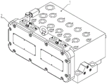
图1为一种智能控制多路换向阀系统的三维结构的正视图。Fig. 1 is a front view of the three-dimensional structure of an intelligent control multi-way reversing valve system.
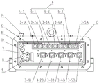
图2为一种智能控制多路换向阀系统的三维结构的后视图。Fig. 2 is a rear view of the three-dimensional structure of an intelligent control multi-way reversing valve system.
图3为一种智能控制多路换向阀系统的箱盖拆卸后的内部结构图。Fig. 3 is a diagram of the internal structure of an intelligent control multi-way reversing valve system after the box cover is disassembled.
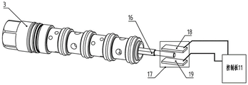
图4为一种智能控制多路换向阀系统的主换向阀阀芯位置检测示意图。Fig. 4 is a schematic diagram of the position detection of the main directional valve spool of an intelligent control multi-way directional valve system.
图5为一种智能控制多路换向阀系统的控制方式示意图。Fig. 5 is a schematic diagram of a control mode of an intelligent control multi-way reversing valve system.
图6为一种智能控制多路换向阀系统的液压系统图。Fig. 6 is a hydraulic system diagram of an intelligent control multi-way reversing valve system.
其中:1、箱体;2、箱盖;3、主换向阀模块;3-1、第一主换向阀;3-2、第二主换向阀;3-3、第三主换向阀;3-4、第四主换向阀;3-5、第五主换向阀;3-1A、第一左位电磁线圈;3-2A、第二左位电磁线圈;3-3A、第三左位电磁线圈;3-4A、第四左位电磁线圈;3-5A、和第五左位电磁线圈;3-1B、第一右位电磁线圈;3-2B、第二右位电磁线圈;3-3B、第三右位电磁线圈;3-4B、第四右位电磁线圈;3-5B、和第五右位电磁线圈;4、安全隔离换向阀;4-1、电磁线圈;5、压力补偿阀模块;5-1、第一压力补偿阀;5-2、第二压力补偿阀;5-3、第三压力补偿阀;5-4、第四压力补偿阀;5-5、第五压力补偿阀;6、先导电磁换向阀模块;6-1、第一先导电磁换向阀;6-2、第二先导电磁换向阀;6-3、第三先导电磁换向阀;7、内部系统压力传感器;8、先导压力传感器;9、外部系统压力传感器;10、回油温度传感器;11、控制板;12、电源板;13、通讯板;14、先导减压阀;15、梭阀模块;15-1、第一梭阀;15-2、第二梭阀;15-3、第三梭阀;15-4、第四梭阀;15-5、第五梭阀;16、阀芯;17、阀芯位置传感器;18、正极板;19、负极板。Among them: 1. Box body; 2. Tank cover; 3. Main reversing valve module; 3-1. First main reversing valve; 3-2. Second main reversing valve; 3-3. Third main reversing valve 3-4, the fourth main directional valve; 3-5, the fifth main directional valve; 3-1A, the first left electromagnetic coil; 3-2A, the second left electromagnetic coil; 3-3A , the third left electromagnetic coil; 3-4A, the fourth left electromagnetic coil; 3-5A, and the fifth left electromagnetic coil; 3-1B, the first right electromagnetic coil; 3-2B, the second right electromagnetic coil Electromagnetic coil; 3-3B, the third right electromagnetic coil; 3-4B, the fourth right electromagnetic coil; 3-5B, and the fifth right electromagnetic coil; 4, safety isolation reversing valve; 4-1, electromagnetic Coil; 5. Pressure compensation valve module; 5-1. First pressure compensation valve; 5-2. Second pressure compensation valve; 5-3. Third pressure compensation valve; 5-4. Fourth pressure compensation valve; 5 -5. Fifth pressure compensation valve; 6. Pilot solenoid directional valve module; 6-1. First pilot solenoid directional valve; 6-2. Second pilot solenoid directional valve; 6-3. Third pilot solenoid Reversing valve; 7. Internal system pressure sensor; 8. Pilot pressure sensor; 9. External system pressure sensor; 10. Oil return temperature sensor; 11. Control board; 12. Power board; 13. Communication board; 14. Pilot reducer Pressure valve; 15, shuttle valve module; 15-1, first shuttle valve; 15-2, second shuttle valve; 15-3, third shuttle valve; 15-4, fourth shuttle valve; 15-5, second shuttle valve Five shuttle valve; 16, spool; 17, spool position sensor; 18, positive plate; 19, negative plate.
具体实施方式detailed description
下面对本实用新型的具体实施方式进行描述,以便于本技术领域的技术人员理解本实用新型,但应该清楚,本实用新型不限于具体实施方式的范围,对本技术领域的普通技术人员来讲,只要各种变化在所附的权利要求限定和确定的本实用新型的精神和范围内,这些变化是显而易见的,一切利用本实用新型构思的实用新型创造均在保护之列。The specific embodiment of the present utility model is described below, so that those skilled in the art understand the utility model, but should be clear, the utility model is not limited to the scope of specific embodiment, for those of ordinary skill in the art, as long as Various changes are within the spirit and scope of the utility model defined and determined by the appended claims, and these changes are obvious, and all utility model creations utilizing the concept of the utility model are all included in the protection list.
如图1所示,在本实用新型的一个实施例中,一种智能控制多路换向阀系统,包括箱体1和箱盖2,所述箱体1上设置有主换向阀模块3、安全隔离换向阀4、压力补偿阀模块5和先导减压阀14;As shown in Figure 1, in one embodiment of the present utility model, an intelligent control multi-way reversing valve system includes a box body 1 and a
其中,所述安全隔离换向阀4设置于所述主换向阀模块3的前端,所述安全隔离换向阀4与主换向阀模块3的油路之间设置有压力补偿阀模块5;Wherein, the safety isolation reversing valve 4 is arranged at the front end of the main reversing
所述主换向阀模块3用于控制主换向阀的液压油流道中压力油的流向,所述安全隔离换向阀4用于当控制板11监测液压系统存在故障时,切断控制主换向阀模块3的总压力油路,压力补偿阀模块5用于调整输入负载油路中的压力,使负载的运行速度不受压力影响,先导减压阀14用于可给液压油流道提供稳定的工作压力。The main reversing
所述箱体1内安装有主换向阀模块3的左位电磁线圈子模块、主换向阀模块3的右位电磁线圈子模块、电磁线圈4-1、先导电磁换向阀模块6、内部系统压力传感器7、先导压力传感器8、外部系统压力传感器9、回油温度传感器10、控制板11、电源板12和通讯板13;所述通讯板13用于提供CAN总线通讯功能。电磁线圈4-1为安全隔离换向阀4的换位电磁线圈。The left electromagnetic coil sub-module of the main reversing
其中,所述内部系统压力传感器7设置于所述主换向阀模块3的压力油路上,所述先导压力传感器8设置于所述先导电磁换向阀模块6的压力油路上,所述回油温度传感器10设置于所述主换向阀模块3的回油路上;Wherein, the internal
所述控制板11分别与所述内部系统压力传感器7、先导压力传感器8、外部系统压力传感器9、回油温度传感器10、电源板12和通讯板13连接。The
各个压力传感器可检测各个油路的压力,并将压力信号传输给控制板11,使控制板11实时监测各油路压力是否正常,并及时诊断各油路是否有故障存在。回油温度传感器10可检测回油温度,并将温度信号传输给控制板11,使控制板11实时监测油温,并诊断油温是否正常。Each pressure sensor can detect the pressure of each oil circuit, and transmit the pressure signal to the
所述主换向阀模块3、安全隔离换向阀4和压力补偿阀模块5均采用插装式阀芯16。The main reversing
如图2所示,所述主换向阀模块3包括第一主换向阀3-1、第二主换向阀3-2、第三主换向阀3-3、第四主换向阀3-4和第五主换向阀3-5;As shown in Figure 2, the main reversing
所述第一主换向阀3-1、第二主换向阀3-2、第三主换向阀3-3、第四主换向阀3-4和第五主换向阀3-5均与所述控制板11连接;The first main reversing valve 3-1, the second main reversing valve 3-2, the third main reversing valve 3-3, the fourth main reversing valve 3-4 and the fifth main reversing valve 3- 5 are all connected to the
当控制板11采集到压力传感器7和温度传感器10提供的信号检测到液压系统油压、油温超出设定范围,或检测到阀芯16卡死,可直接使安全隔离换向阀4断电,切断所有主换向阀模块3的总压力油路,从而保护整个液压系统及设备。When the
所述压力补偿阀模块5包括第一压力补偿阀5-1、第二压力补偿阀5-2、第三压力补偿阀5-3、第四压力补偿阀5-4和第五压力补偿阀5-5。The pressure compensation valve module 5 includes a first pressure compensation valve 5-1, a second pressure compensation valve 5-2, a third pressure compensation valve 5-3, a fourth pressure compensation valve 5-4 and a fifth pressure compensation valve 5 -5.
压力补偿阀模块5使多个液压执行元件在不同速度和压力下同时独立工作,还可以使负载的运行速度不受压力影响。The pressure compensation valve module 5 enables multiple hydraulic actuators to work independently at the same time under different speeds and pressures, and can also make the operating speed of the load not affected by the pressure.
所述左位电磁线圈子模块包括设置于每个主换向阀门上的左位电磁线圈,右位电磁线圈子模块包括设置于每个主换向阀门上的右位电磁线圈;The left electromagnetic coil submodule includes a left electromagnetic coil arranged on each main reversing valve, and the right electromagnetic coil submodule includes a right electromagnetic coil arranged on each main reversing valve;
如图3所示,所述主换向阀模块3的左位电磁线圈子模块包括第一左位电磁线圈3-1A、第二左位电磁线圈3-2A、第三左位电磁线圈3-3A、第四左位电磁线圈3-4A和第五左位电磁线圈3-5A;As shown in Figure 3, the left electromagnetic coil sub-module of the main reversing
所述主换向阀模块3的右位电磁线圈子模块包括第一右位电磁线圈3-1B、第二右位电磁线圈3-2B、第三右位电磁线圈3-3B、第四右位电磁线圈3-4B和第五右位电磁线圈3-5B;The right electromagnetic coil sub-module of the main reversing
第一主换向阀3-1为双作用电磁换向的三位四通阀,其左位和右位换向是分别通过第一左位电磁线圈3-1A、第一右位电磁线圈3-1B通断电来实现换向,从而改变压力油的流向来驱动液压缸或液压马达工作。第二主换向阀3-2、第三主换向阀3-3、第四主换向阀3-4和第五主换向阀3-5与第一主换向阀3-1的设置相同。The first main reversing valve 3-1 is a three-position four-way valve with double-acting electromagnetic reversing. -1B turns on and off to achieve commutation, thereby changing the flow direction of the pressure oil to drive the hydraulic cylinder or hydraulic motor to work. The second main reversing valve 3-2, the third main reversing valve 3-3, the fourth main reversing valve 3-4 and the fifth main reversing valve 3-5 and the first main reversing valve 3-1 The settings are the same.
所述先导电磁换向阀模块6包括第一先导电磁换向阀6-1、第二先导电磁换向阀6-2和第三先导电磁换向阀6-3。The pilot electromagnetic reversing valve module 6 includes a first pilot electromagnetic reversing valve 6-1, a second pilot electromagnetic reversing valve 6-2 and a third pilot electromagnetic reversing valve 6-3.
先导电磁换向阀模块6采用电磁换向二位二通阀,可以给外部液压系统的液压元件提供先导压力油,使本实用新型的多路换向阀适用于各种控制的液压系统中。The pilot electromagnetic reversing valve module 6 adopts an electromagnetic reversing two-position two-way valve, which can provide pilot pressure oil to the hydraulic components of the external hydraulic system, so that the multi-way reversing valve of the present invention is suitable for various controlled hydraulic systems.
所述主换向阀模块3的控制油口之间设置有梭阀模块15;A shuttle valve module 15 is arranged between the control oil ports of the main reversing
所述梭阀模块15包括设置于第一主换向阀3-1、第二主换向阀3-2、第三主换向阀3-3、第四主换向阀3-4和第五主换向阀3-5的控制油口之间的梭阀;在本实施例中,所述梭阀模块15包括第一梭阀15-1、第二梭阀15-2、第三梭阀15-3、第四梭阀15-4和第五梭阀15-5;The shuttle valve module 15 includes the first main reversing valve 3-1, the second main reversing valve 3-2, the third main reversing valve 3-3, the fourth main reversing valve 3-4 and the first main reversing valve 3-4. Shuttle valves between the control oil ports of the five main reversing valves 3-5; in this embodiment, the shuttle valve module 15 includes a first shuttle valve 15-1, a second shuttle valve 15-2, a third shuttle valve valve 15-3, fourth shuttle valve 15-4 and fifth shuttle valve 15-5;
所述梭阀模块15用于把液压执行元件的负载压力通过LS油口反馈给外部液压系统的变量泵,使变量泵根据液压执行元件的负载压力来调整泵的出口压力和流量,从而使液压泵根据负荷自动调整始终工作在最佳节能状态。The shuttle valve module 15 is used to feed back the load pressure of the hydraulic actuator to the variable pump of the external hydraulic system through the LS port, so that the variable pump can adjust the outlet pressure and flow of the pump according to the load pressure of the hydraulic actuator, so that the hydraulic pressure The pump is automatically adjusted according to the load and always works in the best energy-saving state.
如图4所示,所述主换向阀模块3中每个主换向阀的阀芯16末端均安装有阀芯位置传感器17;As shown in Figure 4, a
所述阀芯位置传感器17设置有正极板18和负极板19,所述阀芯16末端位于正极板18和负极板19之间;The
所述阀芯位置传感器17用于测阀芯16位置,判断阀芯16是否卡死。The
当阀芯16处于不同位置时,正极板18和负极板19会产生不同的电信号并传输给控制板11。当阀芯16滑动工作时,控制板11根据采集到的电信号来判断主换向阀模块3中的主换向阀是否卡死。这样可以有效地保护液压系统,避免发生因阀芯16卡死造成的液压执行元件误动作,给人机安全提供保障。When the
如图5所示,控制板11通过通讯板13与外部上位机连接,与上位机实时通讯给上位机提供相关数据并接收执行命令。控制板11连接着内部系统压力传感器7、先导压力传感器8、外部系统压力传感器9、回油温度传感器10、以及5个监测主换向阀3阀芯位置传感器17,接收到各个传感器检测到的数据,并进行分析多路换向阀的液压系统是否正常工作,诊断其故障原因并通过通讯线及时反馈给上位机。控制板11接收到上位机的工作命令可控制并驱动安全隔离换向阀4、主换向阀模块3、先导电磁换向阀模块6进行工作。As shown in FIG. 5 , the
第一主换向阀3-1、第二主换向阀3-2、第三主换向阀3-3、第四主换向阀3-4和第五主换向阀3-5的总压力油路前端均设置1个安全隔离换向阀4,直接控制着主换向阀模块3的压力油路。The first main reversing valve 3-1, the second main reversing valve 3-2, the third main reversing valve 3-3, the fourth main reversing valve 3-4 and the fifth main reversing valve 3-5 A safety isolation reversing valve 4 is arranged at the front end of the total pressure oil circuit, which directly controls the pressure oil circuit of the main reversing
如图6所示,本实用新型提供的一种智能控制多路换向阀系统设置有若干连接油口:As shown in Figure 6, an intelligent control multi-way reversing valve system provided by the utility model is provided with several connecting oil ports:
P口用于连接液压泵或连接满足液压系统工作的压力油液,给智能控制多路换向阀和其控制的执行元件提供满足工作需求的压力油液;T口连接油箱,是液压执行元件工作时的回油口;DR口连接油箱或无压回油管路,是内部液压元件的泄油口;W1口连接外部液压系统的压力油,用于监测外部液压油压力;W2口、W3口和W4口均连接外部液压系统的先导液压元件,给外部液压先导元件提供满足工作的先导压力;A1口和B1口、A2口和B2口、A3口和B3口、A4口和B4口、A5口和B5口——共5组连接口,用于连接液压执行元件,如液压缸或液压马达。The P port is used to connect the hydraulic pump or the pressure oil that meets the working requirements of the hydraulic system to provide the pressure oil that meets the working requirements for the intelligent control multi-way reversing valve and its controlled actuators; the T port is connected to the oil tank and is a hydraulic actuator. The oil return port during work; the DR port is connected to the oil tank or the non-pressure oil return line, which is the oil drain port of the internal hydraulic components; the W1 port is connected to the pressure oil of the external hydraulic system for monitoring the external hydraulic oil pressure; the W2 port and the W3 port Ports A1 and B1, A2 and B2, A3 and B3, A4 and B4, A5 Port and B5 port - a total of 5 groups of connection ports, used to connect hydraulic actuators, such as hydraulic cylinders or hydraulic motors.
如图6所示,A1和B1口内部连接着第一主换向阀3-1,外连接着液压缸,通过对第一主换向阀3-1的换向来改变液压油的流向,从而实现液压缸的伸长和缩短。As shown in Figure 6, the ports A1 and B1 are internally connected to the first main reversing valve 3-1 and externally connected to the hydraulic cylinder. By reversing the first main reversing valve 3-1, the flow direction of the hydraulic oil is changed, thereby Realize the extension and shortening of the hydraulic cylinder.
A2和B2口内部连接第二主换向阀3-2,外部连接着液压马达,通过对第二主换向阀3-2的换向来改变液压油的流向,从而实现液压马达的正转和反转。其余的A3口和B3口、A4口和B4口、A5口和B5口与所述A1口和B1口相同。Ports A2 and B2 are internally connected to the second main reversing valve 3-2, and externally connected to the hydraulic motor. By reversing the second main reversing valve 3-2, the flow direction of the hydraulic oil is changed, thereby realizing the forward rotation and rotation of the hydraulic motor. reverse. The remaining A3 and B3 ports, A4 and B4 ports, A5 and B5 ports are the same as the A1 and B1 ports.
LS口外部连接变量液压泵的变量控制系统,给变量泵反馈液压执行元件的负载压力,使液压泵可以根据负载大小改变其给液压执行元件提供满足工作的液压流量和压力,从事实现液压泵根据负荷变化始终工作在最优的最节能的工作状态下。The LS port is externally connected to the variable control system of the variable hydraulic pump, which feeds back the load pressure of the hydraulic actuator to the variable pump, so that the hydraulic pump can change it according to the load to provide the hydraulic actuator with hydraulic flow and pressure that meet the work, and is engaged in realizing the hydraulic pump according to The load change always works in the optimal and most energy-saving working state.
P口压力油进来分为两路,一路连接着一个安全隔离换向阀4,安全隔离换向阀4采用单作用电磁控制的两位两通阀。安全隔离换向阀4的动作由控制板11控制电磁线圈4-1通电或断电来实现。安全隔离换向阀4主要起到安全隔离的作用,当控制板11采集到内部系统压力传感器7压力过高,或回油温度传感器10温度过高,或阀芯位置传感器17检测到阀芯16卡死,使安全隔离换向阀4关闭液压油路,从而保护液压系统及执行元件。The pressure oil at port P is divided into two paths, one path is connected to a safety isolation reversing valve 4, and the safety isolation reversing valve 4 adopts a two-position two-way valve controlled by single-acting electromagnetic. The action of the safety isolation reversing valve 4 is realized by controlling the power-on or power-off of the electromagnetic coil 4-1 by the
安全隔离换向阀4下端油路分为五路分别接着5个第一压力补偿阀5-1、第二压力补偿阀5-2、第三压力补偿阀5-3、第四压力补偿阀5-4、第五压力补偿阀5-5,5个压力补偿阀下端分别接着5个第一主换向阀3-1、第二主换向阀3-2、第三主换向阀3-3、第四主换向阀3-4、第五主换向阀3-5。每个压力补偿阀的液控口连接着各自主换向阀下端的梭阀。如图4所示,第一梭阀15-1连接着第一主换向阀3-1的第一油口A1和第二油口B1,由于A1口和B1口连接着液压执行元件,所以第一梭阀15-1可以选择性把液压执行元件的负载压力通过LS口反馈给变量液压泵的变量控制系统,同时把也把负载压力反馈给第一压力补偿阀5-1。第一压力补偿阀5-1的作用是可以使本实用新型的智能控制多路换向阀同时控制多个液压执行元件在不同速度和不同负载压力下同时独立工作,不会因其他主换向阀控制的液压执行元件负载压力过大而影响到该路主换向阀控制的液压执行元件的工作压力和速度。第二梭阀15-2、第三梭阀15-3、第四梭阀15-4和第五梭阀15-5与第一梭阀15-1功能相同,第二压力补偿阀5-2、第三压力补偿阀5-3、第四压力补偿阀5-4和第五压力补偿阀5-5与第一压力补偿阀5-1的作用相同。The oil circuit at the lower end of safety isolation reversing valve 4 is divided into five circuits respectively followed by five first pressure compensation valve 5-1, second pressure compensation valve 5-2, third pressure compensation valve 5-3, and fourth pressure compensation valve 5 -4. The fifth pressure compensating valve 5-5, the lower ends of the five pressure compensating valves are respectively connected with five first main reversing valves 3-1, second main reversing valve 3-2, and third main reversing valve 3- 3. The fourth main directional valve 3-4, the fifth main directional valve 3-5. The pilot port of each pressure compensating valve is connected to the shuttle valve at the lower end of each main reversing valve. As shown in Figure 4, the first shuttle valve 15-1 is connected to the first oil port A1 and the second oil port B1 of the first main reversing valve 3-1, since the A1 port and the B1 port are connected to the hydraulic actuator, so The first shuttle valve 15-1 can selectively feed back the load pressure of the hydraulic actuator to the variable control system of the variable hydraulic pump through the LS port, and at the same time feed back the load pressure to the first pressure compensation valve 5-1. The function of the first pressure compensation valve 5-1 is to enable the intelligent control multi-way reversing valve of the present utility model to simultaneously control multiple hydraulic actuators to work independently at different speeds and different load pressures at the same time, and will not be affected by other main reversing valves. The load pressure of the hydraulic actuator controlled by the valve is too large, which affects the working pressure and speed of the hydraulic actuator controlled by the main reversing valve. The second shuttle valve 15-2, the third shuttle valve 15-3, the fourth shuttle valve 15-4 and the fifth shuttle valve 15-5 have the same function as the first shuttle valve 15-1, and the second pressure compensating valve 5-2 , the third pressure compensation valve 5-3, the fourth pressure compensation valve 5-4 and the fifth pressure compensation valve 5-5 have the same functions as the first pressure compensation valve 5-1.
为了适合各种液压系统的外部先导控制而设计三路先导油路,如图6所示,P口压力油进来分为两路,另一路连接着一个先导减压阀14,其把P口进入的压力油减压为满足先导油路需要的工作压力。先导减压阀14下端分为三路先导油路,分别接3个第一先导电磁换向阀6-1、第二先导电磁换向阀6-2和第三先导电磁换向阀6-3。先导电磁换向阀模块6采用单作用电磁换向的两位两通阀,其换向是通过控制板11控制第一先导电磁换向阀6-1、第二先导电磁换向阀6-2和第三先导电磁换向阀6-3的电磁线圈通电或断电来实现。In order to be suitable for the external pilot control of various hydraulic systems, a three-way pilot oil circuit is designed. As shown in Figure 6, the pressure oil at the P port is divided into two lines, and the other line is connected to a pilot
本实用新型的有益效果为:本实用新型采用高度整体集成化,将机械、液压、电子、电控高度优化集成为一体。其内部集成有内部系统压力传感器7、先导压力传感器8、外部系统压力传感器9和回油温度传感器10,可实时监测换向阀液压油的压力、温度;可实时监测换向阀阀芯16的位置,防止因阀芯16卡死而造成人机事故。The beneficial effects of the utility model are: the utility model adopts a high degree of overall integration, and highly optimizes and integrates machinery, hydraulic pressure, electronics, and electric control into one. It integrates internal
本实用新型的多路换向阀集成有CAN总线通讯功能,可与上位机进行实时通讯,并且可通过上位机对其进行操作,易于实现智能化、自动化控制,相比普通换向阀复杂的电路系统,布线简单且易于用户理解操作。The multi-way reversing valve of the utility model is integrated with CAN bus communication function, which can communicate with the upper computer in real time, and can be operated through the upper computer, which is easy to realize intelligent and automatic control, and is more complex than ordinary reversing valves. Circuit system, wiring is simple and easy for users to understand and operate.
在本实用新型的描述中,需要理解的是,术语“中心”、“厚度”、“上”、“下”、“水平”、“顶”、“底”、“内”、“外”、“径向”等指示的方位或位置关系为基于附图所示的方位或位置关系,仅是为了便于描述本实用新型和简化描述,而不是指示或暗示所指的设备或元件必须具有特定的方位、以特定的方位构造和操作,因此不能理解为对本实用新型的限制。此外,术语“第一”、“第二”、“第三”仅用于描述目的,而不能理解为指示或暗示相对重要性或隐含指明的技术特征的数量。因此,限定由“第一”、“第二”、“第三”的特征可以明示或隐含地包括一个或者更多个该特征。In describing the present invention, it should be understood that the terms "center", "thickness", "upper", "lower", "horizontal", "top", "bottom", "inner", "outer", The orientation or positional relationship indicated by "radial" is based on the orientation or positional relationship shown in the drawings, and is only for the convenience of describing the utility model and simplifying the description, rather than indicating or implying that the referred equipment or elements must have a specific Orientation, construction and operation in a particular orientation, therefore should not be construed as limiting the invention. In addition, the terms "first", "second", and "third" are used for descriptive purposes only, and cannot be interpreted as indicating or implying relative importance or implicitly specifying the number of technical features. Therefore, a feature defined by "first", "second" and "third" may explicitly or implicitly include one or more of these features.
Claims (7)
Priority Applications (1)
| Application Number | Priority Date | Filing Date | Title |
|---|---|---|---|
| CN202222237660.4U CN218093679U (en) | 2022-08-24 | 2022-08-24 | An intelligent control multi-way reversing valve system |
Applications Claiming Priority (1)
| Application Number | Priority Date | Filing Date | Title |
|---|---|---|---|
| CN202222237660.4U CN218093679U (en) | 2022-08-24 | 2022-08-24 | An intelligent control multi-way reversing valve system |
Publications (1)
| Publication Number | Publication Date |
|---|---|
| CN218093679U true CN218093679U (en) | 2022-12-20 |
Family
ID=84447114
Family Applications (1)
| Application Number | Title | Priority Date | Filing Date |
|---|---|---|---|
| CN202222237660.4U Active CN218093679U (en) | 2022-08-24 | 2022-08-24 | An intelligent control multi-way reversing valve system |
Country Status (1)
| Country | Link |
|---|---|
| CN (1) | CN218093679U (en) |
Cited By (2)
| Publication number | Priority date | Publication date | Assignee | Title |
|---|---|---|---|---|
| CN115342094A (en) * | 2022-08-24 | 2022-11-15 | 北京道思克矿山装备技术有限公司 | Intelligent control multichannel switching-over valve system |
| CN115791149A (en) * | 2023-01-31 | 2023-03-14 | 博鼎精工智能科技(山东)有限公司 | Multichannel conversion valve intelligent test system |
-
2022
- 2022-08-24 CN CN202222237660.4U patent/CN218093679U/en active Active
Cited By (3)
| Publication number | Priority date | Publication date | Assignee | Title |
|---|---|---|---|---|
| CN115342094A (en) * | 2022-08-24 | 2022-11-15 | 北京道思克矿山装备技术有限公司 | Intelligent control multichannel switching-over valve system |
| CN115791149A (en) * | 2023-01-31 | 2023-03-14 | 博鼎精工智能科技(山东)有限公司 | Multichannel conversion valve intelligent test system |
| CN115791149B (en) * | 2023-01-31 | 2023-05-30 | 博鼎精工智能科技(山东)有限公司 | Intelligent testing system for multi-way reversing valve |
Similar Documents
| Publication | Publication Date | Title |
|---|---|---|
| CN218093679U (en) | An intelligent control multi-way reversing valve system | |
| US20120224983A1 (en) | Multi-way valve, hydraulic device and concrete pump vehicle | |
| CN106382271B (en) | The double spool PLC technology hydraulic valve and its method of a kind of high-speed switch valve pilot control | |
| US7594396B2 (en) | Hydraulic controller for working machine | |
| CN102923188B (en) | Electrically controlled multi-mode steering valve, steering hydraulic control system and wheeled crane | |
| CN111810468B (en) | Pump control hydraulic system, device and control method of turbine engine | |
| CN212297076U (en) | Engineering machinery and positive flow hydraulic system | |
| EP4600768A1 (en) | Can bus-based electronic control unit and control method | |
| GB2440810A (en) | Control valves | |
| CN109826836B (en) | Intelligent variable pump and hydraulic control system | |
| CN116025602A (en) | Hydraulic system of hedge trimming vehicle, boom attitude adjustment method, hedge trimming vehicle | |
| CN117780706A (en) | A modular multi-way valve and its oil circuit system | |
| CN115342094A (en) | Intelligent control multichannel switching-over valve system | |
| CN113915185B (en) | Load port independent control load sensitive multi-way valve and hydraulic system | |
| CN103807236B (en) | Valve control unit loads mouth independently controls multi-cylinder assignment of traffic hydraulic system | |
| CN108716491B (en) | Three-position five-way load port independent control multi-way valve with O-shaped neutral position function | |
| CN120626560A (en) | A constant pressure and load sensitive switching hydraulic control system and control method | |
| CN117006122A (en) | An independent control device, system and control method for multi-way valves | |
| CN212083958U (en) | Double-feedback proportional valve controller | |
| CN212985646U (en) | A hydraulic system and engineering vehicle | |
| CN216401543U (en) | Electrically-controlled proportional steering hydraulic system of loader | |
| CN115818482A (en) | Marine double winch hydraulic power distribution system | |
| CN103486098A (en) | Closed hydraulic system and crane | |
| CN119640896B (en) | Electric rotation control system and method and excavator | |
| CN114876892A (en) | Switchable fine-adjustment quick-action compromise hydraulic system |
Legal Events
| Date | Code | Title | Description |
|---|---|---|---|
| GR01 | Patent grant | ||
| GR01 | Patent grant | ||
| CP03 | Change of name, title or address |
Address after: 100000 Beijing City Chaoyang District Xingfu Second Village Building 39, 5th Floor, Unit 4, Room 502 Patentee after: Beijing Daosike Energy Equipment Co.,Ltd. Country or region after: China Address before: Beijing City Chaoyang District Xingfu Second Village Building 39 5th Floor 4 Unit 502 Patentee before: Beijing daosike mining equipment Technology Co.,Ltd. Country or region before: China |
|
| CP03 | Change of name, title or address |