CN218123761U - Connector and wire-to-board connector - Google Patents
Connector and wire-to-board connector Download PDFInfo
- Publication number
- CN218123761U CN218123761U CN202222027830.6U CN202222027830U CN218123761U CN 218123761 U CN218123761 U CN 218123761U CN 202222027830 U CN202222027830 U CN 202222027830U CN 218123761 U CN218123761 U CN 218123761U
- Authority
- CN
- China
- Prior art keywords
- connector
- drawstring
- lock
- groove
- main body
- Prior art date
- Legal status (The legal status is an assumption and is not a legal conclusion. Google has not performed a legal analysis and makes no representation as to the accuracy of the status listed.)
- Active
Links
Images




Landscapes
- Details Of Connecting Devices For Male And Female Coupling (AREA)
Abstract
Description
技术领域technical field
本实用新型涉及连接器技术领域,特别涉及一种连接器及线对板连接器。The utility model relates to the technical field of connectors, in particular to a connector and a wire-to-board connector.
背景技术Background technique
在通讯产业蓬勃发展之下,各种连接接口持续追求可靠稳定的连接方式,促使连接接口的互锁及解锁结构发展迅速,种类繁多。例如,MCIO(Mini Cool Edge IO,协会定义的I/O界面)连接器是一种应用在高速传输的服务器和交换机中的连接器,其产品体积小,连接可靠稳定。类似MCIO连接器通常金属弹片锁扣作为两个连接器之间的锁止结构,并通过按压弹片或拉带拉动的方式实现解锁。Under the vigorous development of the communication industry, various connection interfaces continue to pursue reliable and stable connection methods, which promotes the rapid development of interlocking and unlocking structures of connection interfaces with various types. For example, MCIO (Mini Cool Edge IO, the I/O interface defined by the Association) connector is a connector used in high-speed transmission servers and switches. Its products are small in size and reliable and stable in connection. Similar to the MCIO connector, the metal shrapnel lock is usually used as a locking structure between the two connectors, and is unlocked by pressing the shrapnel or pulling the strap.
目前设置有拉带的连接器中一般是将拉带直接与锁扣连接配合实现拉动锁扣的功能,拉带容易产生滑动等情况,可靠性较差。At present, in the connector provided with a drawstring, the drawstring is generally directly connected with the lock buckle to realize the function of pulling the lock buckle, and the draw tie is prone to slipping, and the reliability is poor.
实用新型内容Utility model content
本实用新型提供一种连接器及线对板连接器,以解决现有技术中连接器的拉带连接可靠性较差的技术问题。The utility model provides a connector and a wire-to-board connector to solve the technical problem of poor connection reliability of the drawstring of the connector in the prior art.
为解决上述技术问题,本实用新型采用的一个技术方案是提供一种连接器,包括:In order to solve the above technical problems, a technical solution adopted by the utility model is to provide a connector, including:
第一连接器主体;a first connector body;
绝缘体,所述绝缘体的至少部分嵌设于所述第一连接器主体内,所述绝缘体上设置有锁扣,所述锁扣用于与另一连接器配合连接;an insulator, at least part of which is embedded in the first connector body, and a lock is provided on the insulator, and the lock is used for mating connection with another connector;
连接器后盖,盖设于所述第一连接器主体,所述连接器后盖形成有安装槽,所述连接器后盖的顶面对应所述安装槽设置有抵接凸起;The connector back cover is set on the first connector body, the connector back cover is formed with a mounting groove, and the top surface of the connector back cover is provided with an abutment protrusion corresponding to the installation groove;
拉带,贯穿所述安装槽以与所述锁扣连接,且所述拉带与所述抵接凸起抵接,所述拉带用于受力带动所述锁扣脱离所述另一连接器。a drawstring, which passes through the installation groove to be connected with the lock, and the drawstring abuts against the abutting protrusion, and the drawstring is used to force the lock to break away from the other connection device.
在一具体实施例中,所述拉带包括连接的拉带主体及连接部,所述拉带主体贯穿所述安装槽,所述连接部与所述抵接凸起抵接。In a specific embodiment, the drawstring includes a connected drawstring main body and a connecting portion, the drawstring main body passes through the installation groove, and the connecting portion abuts against the abutting protrusion.
在一具体实施例中,所述拉带主体的厚度小于或等于所述安装槽的厚度,所述连接部的厚度大于所述安装槽的厚度。In a specific embodiment, the thickness of the drawstring main body is less than or equal to the thickness of the installation groove, and the thickness of the connecting portion is greater than the thickness of the installation groove.
在一具体实施例中,所述拉带还包括手持部,所述手持部连接于所述拉带主体远离所述连接部的一端,所述手持部的宽度大于所述拉带主体的宽度。In a specific embodiment, the drawstring further includes a handle part, the handle part is connected to an end of the drawstring main body away from the connection part, and the width of the handle part is larger than the width of the drawstring main body.
在一具体实施例中,所述锁扣包括:In a specific embodiment, the lock includes:
锁扣主体,所述锁扣主体与所述绝缘体连接,所述锁扣主体用于与另一连接器配合连接;A lock body, the lock body is connected to the insulator, and the lock body is used to cooperate with another connector;
连接件,与所述锁扣主体连接,所述连接件形成有连接槽,所述拉带通过所述连接槽与所述连接件连接。The connecting piece is connected with the buckle main body, the connecting piece is formed with a connecting groove, and the drawstring is connected with the connecting piece through the connecting groove.
在一具体实施例中,所述第一连接器主体设置有第一容置槽及对应所述第一容置槽的防护件,所述锁扣容置于所述第一容置槽内,所述锁扣的至少部分被所述防护件遮挡。In a specific embodiment, the first connector body is provided with a first accommodating groove and a guard corresponding to the first accommodating groove, the lock catch is accommodated in the first accommodating groove, At least part of the buckle is covered by the guard.
在一具体实施例中,所述防护件凸出于所述第一连接器主体设置,所述防护件形成有与所述第一容置槽连通的第二容置槽,用于容置所述连接件。In a specific embodiment, the protective piece protrudes from the first connector body, and the protective piece is formed with a second accommodation groove communicating with the first accommodation groove for accommodating the the connectors described above.
在一具体实施例中,所述防护件呈条状设置,用于遮挡所述连接件的至少部分,所述连接部设置于所述防护件与所述连接器后盖之间。In a specific embodiment, the protective piece is arranged in a strip shape for covering at least part of the connecting piece, and the connecting portion is arranged between the protective piece and the connector back cover.
在一具体实施例中,所述防护件包括呈条状设置的防护件主体部及凸出于所述防护件主体部朝向所述连接器后盖一侧的凸起部,所述防护件用于遮挡所述连接件,所述连接部夹持于所述防护件与所述连接器后盖之间。In a specific embodiment, the protective piece includes a main body portion of the protective piece arranged in a strip shape and a raised portion protruding from the main body portion of the protective piece toward the side of the connector rear cover, and the protective piece is used for In order to cover the connecting piece, the connecting portion is clamped between the protective piece and the connector back cover.
为解决上述技术问题,本实用新型采用的另一个技术方案是提供一种线对板连接器,包括线端连接器和板端连接器,所述线端连接器为上述的连接器,所述板端连接器包括第二连接器主体,所述第二连接器主体上形成有限位槽,所述锁扣与所述限位槽配合限位。In order to solve the above technical problems, another technical solution adopted by the utility model is to provide a wire-to-board connector, including a wire-end connector and a board-end connector, the wire-end connector is the above-mentioned connector, and the The board end connector includes a second connector main body, a limiting groove is formed on the second connector main body, and the lock catch cooperates with the limiting groove to limit the position.
本实用新型连接器包括第一连接器主体、绝缘体、连接器后盖以及拉带,绝缘体的至少部分嵌设于第一连接器主体内,绝缘体上设置有锁扣用于与另一连接器配合连接,连接器后盖盖设于第一连接器主体,连接器后盖形成有安装槽,连接器后盖的顶面对应安装槽设置有抵接凸起,拉带贯穿安装槽以与锁扣连接,且拉带与抵接凸起抵接,拉带用于受力带动锁扣脱离另一连接器,其中,拉带不仅可以通过与锁扣的连接施力,还可以通过与连接器后盖的抵接凸起抵接向连接器后盖施力,便于连接器与另一连接器的脱离解锁,可靠性更高。The connector of the utility model includes a first connector body, an insulator, a connector back cover and a drawstring, at least part of the insulator is embedded in the first connector body, and a lock is provided on the insulator for matching with another connector. connection, the connector back cover is set on the first connector body, the connector back cover is formed with a mounting groove, the top surface of the connector back cover is provided with an abutting protrusion corresponding to the mounting groove, and the drawstring passes through the mounting groove to be in contact with the lock The buckle is connected, and the drawstring abuts against the abutment protrusion, and the drawstring is used to drive the buckle away from the other connector under force, wherein the drawstring can not only exert force through the connection with the buckle, but also can The abutment protrusion of the back cover abuts against the back cover of the connector to exert force, which facilitates the disengagement and unlocking of the connector from another connector, and has higher reliability.
附图说明Description of drawings
为了更清楚地说明本实用新型实施例中的技术方案,下面将对实施例描述中所需要使用的附图作简单地介绍,显而易见地,下面描述中的附图仅仅是本实用新型的一些实施例,对于本领域普通技术人员来讲,在不付出创造性劳动的前提下,还可以根据这些附图获得其他的附图,其中:In order to more clearly illustrate the technical solutions in the embodiments of the present invention, the accompanying drawings that need to be used in the description of the embodiments will be briefly introduced below. Obviously, the accompanying drawings in the following description are only some implementations of the present invention. For example, those of ordinary skill in the art can also obtain other drawings based on these drawings without creative work, where:
图1是本实用新型连接器一实施例的立体结构示意图;Fig. 1 is a three-dimensional structural schematic diagram of an embodiment of the utility model connector;
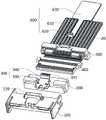
图2是本实用新型连接器一实施例的爆炸结构示意图;Fig. 2 is a schematic diagram of an explosion structure of an embodiment of the utility model connector;
图3是本实用新型连接器一实施例的剖视结构示意图;Fig. 3 is a schematic cross-sectional structure diagram of an embodiment of the utility model connector;
图4是本实用新型连接器一实施例中第一连接器主体的立体结构示意图;Fig. 4 is a three-dimensional structural schematic view of the first connector body in an embodiment of the connector of the present invention;
图5是本实用新型连接器另一实施例的立体结构示意图;Fig. 5 is a three-dimensional structural schematic view of another embodiment of the connector of the present invention;
图6是本实用新型连接器另一实施例的爆炸结构示意图;Fig. 6 is a schematic diagram of the exploded structure of another embodiment of the connector of the present invention;
图7是本实用新型连接器另一实施例中连接器后盖的立体结构示意图;Fig. 7 is a three-dimensional structural schematic diagram of the connector back cover in another embodiment of the connector of the present invention;
图8是本实用新型连接器另一实施例的立体结构示意图;Fig. 8 is a three-dimensional structural schematic view of another embodiment of the connector of the present invention;
图9是本实用新型连接器另一实施例的爆炸结构示意图;Fig. 9 is a schematic diagram of an exploded structure of another embodiment of the connector of the present invention;
图10是本实用新型连接器另一实施例中连接器后盖的立体结构示意图;Fig. 10 is a schematic perspective view of the three-dimensional structure of the connector back cover in another embodiment of the connector of the present invention;
图11是本实用新型线对板连接器实施例的立体结构示意图;Fig. 11 is a schematic diagram of a three-dimensional structure of an embodiment of a wire-to-board connector of the present invention;
图12是本实用新型线对板连接器实施例另一状态的立体结构示意图。Fig. 12 is a schematic perspective view of another state of the wire-to-board connector embodiment of the present invention.
具体实施方式detailed description
下面将结合本实用新型实施例中的附图,对本实用新型实施例中的技术方案进行清楚、完整地描述,显然,所描述的实施例仅仅是本实用新型一部分实施例,而不是全部的实施例。基于本实用新型中的实施例,本领域普通技术人员在没有做出创造性劳动前提下所获得的所有其他实施例,均属于本实用新型保护的范围。The technical solutions in the embodiments of the present invention will be clearly and completely described below in conjunction with the accompanying drawings in the embodiments of the present invention. Obviously, the described embodiments are only part of the embodiments of the present invention, not all of them. example. Based on the embodiments of the present utility model, all other embodiments obtained by persons of ordinary skill in the art without making creative efforts belong to the scope of protection of the present utility model.
本申请中的术语“第一”、“第二”仅用于描述目的,而不能理解为指示或暗示相对重要性或者隐含指明所指示的技术特征的数量。本申请的描述中,“多个”的含义是至少两个,例如两个,三个等,除非另有明确具体的限定。此外,术语“包括”和“具有”以及它们任何变形,意图在于覆盖不排他的包含。例如包含了一系列步骤或单元的过程、方法、系统、产品或设备没有限定于已列出的步骤或单元,而是可选地还包括没有列出的步骤或单元,或可选地还包括对于这些过程、方法、产品或设备固有的其它步骤或单元。而术语“和/或”,仅仅是一种描述关联对象的关联关系,表示可以存在三种关系,例如,A和/或B,可以表示:单独存在A,同时存在A和B,单独存在B这三种情况。另外,本文中字符“/”,一般表示前后关联对象是一种“或”的关系。The terms "first" and "second" in this application are only used for descriptive purposes, and should not be understood as indicating or implying relative importance or implicitly specifying the quantity of indicated technical features. In the description of the present application, "plurality" means at least two, such as two, three, etc., unless otherwise specifically defined. Furthermore, the terms "include" and "have", as well as any variations thereof, are intended to cover a non-exclusive inclusion. For example, a process, method, system, product or device comprising a series of steps or units is not limited to the listed steps or units, but optionally also includes unlisted steps or units, or optionally further includes For other steps or units inherent in these processes, methods, products or apparatuses. The term "and/or" is just an association relationship describing associated objects, which means that there can be three relationships, for example, A and/or B, which can mean: A exists alone, A and B exist simultaneously, and B exists alone These three situations. In addition, the character "/" in this article generally indicates that the contextual objects are an "or" relationship.
参见图1至图4,本实用新型连接器10一实施例包括第一连接器主体100及绝缘体200,第一连接器主体100形成有第一容置槽110,第一连接器主体100上对应第一容置槽110设置有防护件120,绝缘体200与第一连接器主体100连接,绝缘体200上设置有锁扣300,锁扣300容置于第一容置槽110内,且锁扣300的至少部分被防护件120遮挡,能够避免锁扣300被误按或被线缆等其他部件误压,能够使得连接器10不易脱落,连接的可靠性更好,通过设置防护件120能够增强第一连接器主体100的强度,还能够增加第一连接器主体100的厚度,使得第一连接器主体100的制备难度更低,进而使得连接器10具备更好的可制造性。1 to 4, an embodiment of the
在本实施例中,第一连接器主体100可以为塑胶材料制成,锁扣300为金属材料制成,能够使得锁扣300的强度更高,且便于第一连接器主体100与锁扣300的扣合锁定。In this embodiment, the
在本实施例中,绝缘体200可以为塑胶材料制成,能够起到绝缘作用,避免短路。In this embodiment, the
在本实施例中,锁扣300包括锁扣主体310及按压件320,锁扣主体310与绝缘体200连接,锁扣主体310用于与另一连接器配合连接,按压件320与锁扣主体310连接,使得按压件320受力下压后,锁扣主体310能够脱离另一连接器,防护件120用于遮挡按压件320的至少部分,使得按压件320不易被误按或误压。In this embodiment, the
在本实施例中,定义图3所示的前后方向为第一方向,左右方向为第二方向,上下方向为第三方向。In this embodiment, the front-rear direction shown in FIG. 3 is defined as the first direction, the left-right direction as the second direction, and the up-down direction as the third direction.
在本实施例中,防护件120沿第一方向跨接于第一容置槽110的两侧,防护件120沿与第一方向垂直的第二方向的宽度小于按压件320沿第二方向的宽度,使得防护件120能够遮挡按压件320的部分,使得按压件320不易被误按或误压,同时在需要解锁连接器10时能够通过按压件320未被遮挡的部分实现按压解锁。In this embodiment, the
在本实施例中,防护件120沿第三方向凸出于第一连接器主体100设置,防护件120形成有与第一容置槽110连通的第二容置槽121,用于容置按压件320,能够避免防护件120与锁扣300干涉。In this embodiment, the
在本实施例中,锁扣主体310包括第一弹片311和第二弹片312,第一弹片311的第一端分别与绝缘体200和按压件320连接,第一弹片311的第二端与第二弹片312连接,使得按压件320能够通过受力带动第一弹片311相对第二弹片312靠拢或分离,以实现与另一连接器的扣合。In this embodiment, the locking
在本实施例中,第一弹片311上设置有第一限位凸起313,第一限位凸起313用于与另一连接器的第一限位槽(图中未示出)配合限位,第二弹片312上设置有第二限位槽314,第一连接器主体100上形成有第二限位凸起111,第二限位凸起111与第二限位槽314配合限位,使得锁扣300能够与第一连接器主体100之间的连接更加稳固,锁扣300与另一连接器之间的连接也更加稳固。In this embodiment, the first
在本实施例中,按压件320上设置有凸起321,凸起321呈长条形设置,能够增加按压件320的表面与施力物(例如手指)之间的摩擦力,便于对按压件320施力。In this embodiment, the pressing
在本实施例中,连接器10还包括电路板400以及连接器后盖500,绝缘体200的至少部分嵌设于第一连接器主体100内,电路板400嵌设于绝缘体200内,连接器后盖500盖设于第一连接器主体100,能够将电路板400固定于绝缘体200内。In this embodiment, the
在本实施例中,第一连接器主体100还可以形成有电路板安装槽130,第一连接器主体100对应电路板安装槽130还设置有导向筋140,电路板400能够沿导向筋140插置于电路板安装槽130内。In this embodiment, the
在本实施例中,第一连接器主体100还可以形成有容置空间150以及注塑孔160,以通过注塑孔160在容置空间150内注塑形成绝缘体200,使得连接器10的整体结构更加紧凑,稳固。In this embodiment, the
在本实施例中,第一连接器主体100还可以形成有卡扣孔170,连接器后盖500上设置有卡扣凸起510,卡扣孔170与卡扣凸起510配合实现卡扣,能够使得第一连接器主体100和连接器后盖500之间的连接更加稳固。In this embodiment, the
在其他实施例中,也可以为第一连接器主体100上设置有卡扣凸起,连接器后盖500上设置有对应卡扣孔,在此不做限制。In other embodiments, the first connector
在本实施例中,第一连接器主体100还可以形成有卡扣预装槽180,连接器后盖500上还设置有卡扣520,卡扣预装槽180和卡扣520配合实现限位。In this embodiment, the
在本实施例中,连接器10可以为线端连接器,线缆20通过连接器后盖500与电路板400连接。In this embodiment, the
在其他实施例中,连接器10也可以为板端连接器,在此不做限制。In other embodiments, the
参见图5至图7,本实用新型连接器10另一实施例包括第一连接器主体100、绝缘体200、连接器后盖500以及拉带600,绝缘体200的至少部分嵌设于第一连接器主体100内,绝缘体200上设置有锁扣300,锁扣300用于与另一连接器配合连接,连接器后盖500盖设于第一连接器主体100,连接器后盖500形成有安装槽530,连接器后盖500的顶面对应安装槽530设置有抵接凸起540,拉带600贯穿安装槽530以与锁扣300连接,且拉带600与抵接凸起540抵接,拉带600用于受力带动锁扣300脱离另一连接器,其中,拉带600不仅可以通过与锁扣300的连接施力,还可以通过与连接器后盖500的抵接凸起540抵接向连接器后盖500施力,便于连接器10与另一连接器的脱离解锁,可靠性更高。5 to 7, another embodiment of the
在本实施例中,锁扣主体330的结构与上述连接器10实施例中的锁扣主体310的结构类似,在此不再赘述。In this embodiment, the structure of the locking
在本实施例中,拉带600包括连接的拉带主体610及连接部620,拉带主体610贯穿安装槽530,连接部620与锁扣300连接,且与抵接凸起540抵接,使得连接器后盖500也能够受力带动连接器10运动。In this embodiment, the
在本实施例中,拉带主体610的厚度小于或等于安装槽530的厚度,便于拉带600的安装,连接部620的厚度大于安装槽530的厚度,能够避免连接部620从安装槽530脱落。In this embodiment, the thickness of the drawstring
在本实施例中,拉带600还可以包括手持部630,手持部630连接于拉带主体610远离连接部620的一端,手持部630的宽度大于拉带主体610的宽度,便于用户手持。In this embodiment, the
在本实施例中,锁扣300包括锁扣主体330及连接件340,锁扣主体330与绝缘体200连接,锁扣主体330用于与另一连接器配合连接,连接件340与锁扣主体330连接,连接件340形成有连接槽341,拉带600通过连接槽341与连接件340连接,以使得拉带600能够带动锁扣300运动。In this embodiment, the
在本实施例中,第一连接器主体100设置有第一容置槽110及对应第一容置槽110的防护件120,锁扣300容置于第一容置槽110内,锁扣300的至少部分被防护件120遮挡,能够避免连接件340被误按或误压以造成连接器10与另一连接器脱离。本实施例通过设置防护件120,能够避免锁扣300被误按或被线缆等其他部件误压,能够使得连接器10不易脱落,连接的可靠性更好,通过设置防护件120还能够增强第一连接器主体100的强度,还能够增加第一连接器主体100的厚度,使得第一连接器主体100的制备难度更低,进而使得连接器10具备更好的可制造性,通过设置拉带600能够便于连接器的解锁。In this embodiment, the
一并参见图4,在本实施例中,防护件120沿第一方向跨接于第一容置槽110的两侧,防护件120沿与第一方向垂直的第二方向的宽度小于连接件340沿第二方向的宽度,使得防护件120能够遮挡连接件340的部分,使得连接件340不易被误按或误压。Referring to FIG. 4 together, in this embodiment, the
在本实施例中,防护件120沿第三方向凸出于第一连接器主体100设置,防护件120形成有与第一容置槽110连通的第二容置槽121,用于容置连接件340,能够避免防护件120与锁扣300干涉。In this embodiment, the
在本实施例中,防护件120呈条状设置,用于遮挡连接件340的至少部分,连接部620设置于防护件120与连接器后盖500之间,使得拉带600损坏或者不便于拉动时,连接件340外露于防护件120的部分还可以用于受力,以实现解锁。In this embodiment, the
参见图8和图9,本实用新型连接器10另一实施例包括第一连接器主体100、绝缘体200以及拉带600,绝缘体200及拉带600的结构参见上述连接器10实施例,在此不再赘述。Referring to FIG. 8 and FIG. 9, another embodiment of the
一并参见图10,本实施例与上述实施例的不同之处在于,在本实施例中,防护件190包括呈条状设置的防护件主体部191及凸出于防护件主体部191朝向连接器后盖500一侧的凸起部192,防护件190用于遮挡连接件340的全部,能够使得遮挡效果更好,进一步避免连接件340被误压或误按,连接部340夹持于防护件120与连接器后盖500之间,能够使得拉带600与第一连接器主体100的连接更加稳固。Referring to FIG. 10 together, the difference between this embodiment and the above-mentioned embodiments is that in this embodiment, the
在本实施例中,连接器10还包括电路板400,电路板400嵌设于绝缘体200内,连接器后盖500能够将电路板400固定于绝缘体200内。In this embodiment, the
在本实施例中,电路板400用于与线缆20连接。In this embodiment, the
参见图11和图12,本实用新型线对板连接器包括线端连接器和板端连接器30,线端连接器为上述的连接器10,板端连接器30包括第二连接器主体700,第二连接器主体700上形成有限位槽710,锁扣300与限位槽710配合限位。本实施例通过设置防护件120,能够避免锁扣300被误按或被线缆等其他部件误压,能够使得连接器10不易脱落,连接的可靠性更好,通过设置防护件120还能够增强第一连接器主体100的强度,还能够增加第一连接器主体100的厚度,使得第一连接器主体100的制备难度更低,进而使得连接器10具备更好的可制造性。Referring to Fig. 11 and Fig. 12, the wire-to-board connector of the present invention includes a wire-end connector and a board-
以上所述仅为本实用新型的实施方式,并非因此限制本实用新型的专利范围,凡是利用本实用新型说明书及附图内容所作的等效结构或等效流程变换,或直接或间接运用在其他相关的技术领域,均同理包括在本实用新型的专利保护范围内。The above is only the embodiment of the utility model, and does not limit the patent scope of the utility model. Any equivalent structure or equivalent process transformation made by using the utility model specification and accompanying drawings, or directly or indirectly used in other Related technical fields are all included in the patent protection scope of the present utility model in the same way.
Claims (10)
Priority Applications (1)
| Application Number | Priority Date | Filing Date | Title |
|---|---|---|---|
| CN202222027830.6U CN218123761U (en) | 2022-08-02 | 2022-08-02 | Connector and wire-to-board connector |
Applications Claiming Priority (1)
| Application Number | Priority Date | Filing Date | Title |
|---|---|---|---|
| CN202222027830.6U CN218123761U (en) | 2022-08-02 | 2022-08-02 | Connector and wire-to-board connector |
Publications (1)
| Publication Number | Publication Date |
|---|---|
| CN218123761U true CN218123761U (en) | 2022-12-23 |
Family
ID=84521923
Family Applications (1)
| Application Number | Title | Priority Date | Filing Date |
|---|---|---|---|
| CN202222027830.6U Active CN218123761U (en) | 2022-08-02 | 2022-08-02 | Connector and wire-to-board connector |
Country Status (1)
| Country | Link |
|---|---|
| CN (1) | CN218123761U (en) |
-
2022
- 2022-08-02 CN CN202222027830.6U patent/CN218123761U/en active Active
Similar Documents
| Publication | Publication Date | Title |
|---|---|---|
| US5486117A (en) | Locking system for an electrical connector assembly | |
| US6565383B1 (en) | Electrical connector with locking member | |
| US20050282424A1 (en) | Electrical connector with latching device | |
| CA1228402A (en) | Electrical connector with multifunction lock means | |
| CN210779276U (en) | Connector with a locking member | |
| CN117154466A (en) | Second connector | |
| JP2003243093A (en) | USB connector | |
| TWM595343U (en) | Connector | |
| US6132241A (en) | Electrical connector assembly having protection partition | |
| US6450830B1 (en) | Electrical connector having improved latching means | |
| US6749458B1 (en) | Cable end connector assembly having pull member | |
| CN212257885U (en) | Connector and electric connecting device | |
| CN100557896C (en) | Cable connector | |
| TW201342733A (en) | Electric connector for flat conductor and method for assembling electric connector with flat conductor | |
| US20060141867A1 (en) | Cable assembly with improved engaging means | |
| CN216289282U (en) | Connector with unlocking pull belt | |
| US8425248B2 (en) | Plug electrical connector with elastic latch | |
| CN210007015U (en) | Electrical connector | |
| CN210779297U (en) | Connector with a locking member | |
| CN218123761U (en) | Connector and wire-to-board connector | |
| CN218070431U (en) | Connector and wire-to-board connector | |
| CN107230885A (en) | The connector of with locking mechanism | |
| CN219040921U (en) | Lock catch retaining device and connector assembly | |
| CN202678632U (en) | Latch device of wire-to-board connector | |
| CN218215941U (en) | Anti-removal device for single-pair Ethernet connector assembly |
Legal Events
| Date | Code | Title | Description |
|---|---|---|---|
| GR01 | Patent grant | ||
| GR01 | Patent grant |