CN218138024U - Scriber - Google Patents
Scriber Download PDFInfo
- Publication number
- CN218138024U CN218138024U CN202222353272.2U CN202222353272U CN218138024U CN 218138024 U CN218138024 U CN 218138024U CN 202222353272 U CN202222353272 U CN 202222353272U CN 218138024 U CN218138024 U CN 218138024U
- Authority
- CN
- China
- Prior art keywords
- scriber
- scribe
- scribing
- screw
- screw rod
- Prior art date
- Legal status (The legal status is an assumption and is not a legal conclusion. Google has not performed a legal analysis and makes no representation as to the accuracy of the status listed.)
- Active
Links
- 230000006641 stabilisation Effects 0.000 abstract description 2
- 238000011105 stabilization Methods 0.000 abstract description 2
- 230000000903 blocking effect Effects 0.000 description 6
- 238000005520 cutting process Methods 0.000 description 3
- 238000005034 decoration Methods 0.000 description 3
- 238000009434 installation Methods 0.000 description 2
- 238000000034 method Methods 0.000 description 1
- 238000012986 modification Methods 0.000 description 1
- 230000004048 modification Effects 0.000 description 1
- 238000006467 substitution reaction Methods 0.000 description 1
- 239000002023 wood Substances 0.000 description 1
Images




Landscapes
- Knives (AREA)
Abstract
The utility model discloses a scriber, which comprises a scriber body, wherein a scribing blade is arranged on the scriber body; the middle part of the scriber body is provided with a first threaded through hole, a screw rod with scale marks is screwed in the first threaded through hole and is connected with the base, and the scriber body can rotate along the screw rod and further move up and down; a locking piece is arranged on one side of the scriber body, which is far away from the base, and the locking piece is in threaded connection with the screw rod to fix the scriber body. The utility model has the advantages of simple structure and design benefit, convenient operation is swift, job stabilization is reliable, through the scale mark on screw rod surface, can the accurate adjustment marking distance, and the marking time is short, improves the accuracy and the work efficiency of marking off greatly.
Description
Technical Field
The utility model relates to a scriber is applicable to and rules out panel when house decoration.
Background
Modern house decoration is a complex project of a system, and a large amount of finished boards are needed to be used when various wooden house decoration articles such as suspended ceiling installation, skirting line installation, shoe cabinets, wardrobes, storage cabinets, tatami and the like are required to be manufactured and installed, and the boards are often large in size and generally need to be cut and processed to adapt to specific sizes and patterns of different houses. The cutting process often needs to mark a line in advance on the plate, the size is determined in advance, the size after the cutting is convenient to be accurate, at the present stage, an operator often depends on a triangular ruler and a pen to carry out manual operation when marking the line, and when the long straight line cutting is processed, a flexible tape ruler is often used, or the triangular ruler is continuously used for carrying out repeated splicing marking, time and labor are wasted, and the marking accuracy cannot be guaranteed.
Disclosure of Invention
The utility model provides a scriber, this scriber simple structure easily operates and work efficiency is high, and concrete technical scheme is as follows:
a scriber is characterized by comprising a scriber body, wherein a scribing blade is arranged on the scriber body; the middle part of the scriber body is provided with a first threaded through hole, a screw rod with scale marks is screwed in the first threaded through hole and is connected with the base, and the scriber body can rotate along the screw rod and further move up and down; a locking piece is arranged on one side of the scriber body, which is far away from the base, and the locking piece is in threaded connection with the screw rod to fix the scriber body.
The scriber body is triangular, cutter grooves are formed in 3 corner portions of the triangular scriber body, first threaded holes are formed in the cutter grooves, and the scribing blades are fixed on the cutter grooves of the scriber body through first bolts.
The scribing blades are triangular, the number of the scribing blades is 3, and the scribing blades are respectively fixed at 3 corner parts of the scriber body.
The 3 angles of the scriber body are plane angles, so that the cutter point part of the scribing cutter blade can be exposed out of the cutter groove.
One side of the cutter groove is provided with a blocking edge, the bottom edge of the scribing blade is abutted to the blocking edge, and the blocking edge can be used for positioning when the scribing blade is installed.
When marking off, for the convenience of handheld scriber body, the equipartition is provided with the recess on the outer wall of scriber body.
The two sides of the screw rod are planes, corresponding scale marks are arranged on the planes on the two sides of the screw rod, and the scribing distance can be accurately adjusted through the scale marks.
The bottom of the screw rod is provided with a second threaded hole, and the base is fixedly connected with the screw rod through a second screw.
The top of the screw is provided with a screw head, and the outer surface of the screw head is provided with an anti-skid rib.
The outer side of the base is provided with a rubber pad which is sleeved on the base.
The utility model has the advantages of simple structure and ingenious design, convenient operation is swift, job stabilization is reliable, through the scale mark on screw rod surface, can accurate adjustment marking distance, and marking time is short, improves the accuracy and the work efficiency of marking off greatly.
Drawings
Fig. 1 is a perspective view of the present invention;
fig. 2 is a perspective view 1 of the present invention during adjustment;
fig. 3 is a perspective view 2 of the present invention during adjustment;
fig. 4 is a front view of the present invention;
fig. 5 is an exploded view of the present invention;
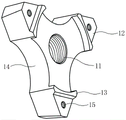
fig. 6 is a perspective view of the scriber body of the present invention;
FIG. 7 is a right side view of the screw of the present invention;
fig. 8 is a left side view of the screw of the present invention.
Detailed Description
In order to better understand the purpose, function and specific design of the present invention, the following detailed description of the line drawing device is made with reference to the accompanying drawings.
As shown in fig. 1-5, the utility model comprises a scriber body 1, and a scribing blade 2 is arranged on the scriber body 1. The middle part of the scriber body 1 is provided with a first threaded through hole 11, the screw rod 3 is screwed in the first threaded through hole 11 and is connected with the base 5, and the base 5 is arranged to assist the moving scriber to scribe. The scriber body 1 can rotate along the screw rod 3 and then move up and down. One side of the scriber body 1 far away from the base 5 is provided with a locking part 4, the middle part of the locking part 4 is provided with a second threaded through hole 41 matched with the screw rod 3, and the locking part 4 is in threaded connection with the screw rod 3 to fix the scriber body 1.
Specifically, as shown in fig. 2, 5 and 6, the scribe body 1 has a triangular shape, and sipes 12 are provided in 3 corners of the triangular scribe body 1. The cutter groove 12 is provided with a first threaded hole 15, the scribing blade 2 is provided with a through hole 21, and the first screw 6 penetrates through the through hole 21 on the scribing blade 2 and is screwed in the first threaded hole 15 of the scriber body 1 to fix the scribing blade 2 on the cutter groove 12 of the scriber body 1.
The scribing blades 2 are triangular, the number of the scribing blades 2 is 3, and the scribing blades are respectively fixed at 3 corners of the scriber body 1. The 3 angles of the scriber body 1 are plane angles, so that the edge part of the scribing blade 2 can be exposed out of the cutter groove 12. One side of the cutter groove 12 is provided with a blocking edge 13, the bottom edge of the scribing blade 2 is abutted against the blocking edge 13, and the blocking edge 13 can be used for positioning when the scribing blade 2 is installed, so that the cutter point part of the scribing blade 2 can just be exposed out of the cutter groove 12 when the scribing blade 2 is installed.
When marking off, for the convenience of holding the scriber body 1 by hands, the grooves 14 are uniformly distributed on the outer wall of the scriber body 1.
When scribing, only one scribing blade 2 performs scribing work, and the specific description is given by taking one scribing blade 2 as an example, the exposed knife point part at one end of the scribing blade 2 performs scribing, and the knife point parts at the other two ends are reserved for standby. After the point of the scribing blade 2 contacting with the plate is worn in a long-time working state, the first screw 6 is unscrewed, and the scribing blade 2 is rotated to enable the point of the other end of the scribing blade 2 to contact with the plate in the scribing process, so that the point of the other end of the scribing blade 2 can be used instead of the point of the plate. Of course, for greater convenience, two more scoring blades 2 may be used to perform the scoring operation.
As shown in fig. 3, 7 and 8, the two sides of the screw rod 3 are provided with planes 31, the planes 31 on the two sides of the screw rod 3 are provided with corresponding scale marks, the scribing distance can be accurately adjusted through the scale marks, the scale marks on the two sides of the screw rod 3 are marked with scale values in different manners, and during adjustment, which scale mark can be selected and observed according to needs. The bottom of the screw rod 3 is provided with a second threaded hole 32, and the second screw 7 passes through the central hole of the base 5 and is screwed in the second threaded hole 32 of the screw rod 3, so that the base 5 and the screw rod 3 are connected and fixed. The top of the screw 3 is provided with a screw head 33, and the outer surface of the screw head 33 is provided with an anti-slip rib 331.
The outer side of the base 5 is provided with a rubber pad 51, and the rubber pad 51 is sleeved on the base 5 and used for preventing the base 5 from wearing floor tiles or wood floors when marking.
The utility model discloses the use does: firstly, placing the scribing blade 2 on the cutter groove 12 of the scriber body 1, and then screwing a first screw 6 in a first threaded hole 15 of the scriber body 1 to finish fixing the scribing blade 2; loosening the locking part 4, wherein when the locking part 4 is loosened, one hand holds the screw head 33, and the other hand rotates the locking part 4, so that the locking part 4 rotates and rises along the screw rod 3 to be separated from fixing the scriber body 1; then the scriber body 1 is rotated to enable the scriber body 1 to ascend or descend along the screw rod 3, when the scriber body 1 is adjusted, the scale marks on the surface of the screw rod 3 are utilized, so that the scribing distance can be accurately adjusted, the locking piece 4 is screwed after the adjustment is finished, and the scriber body 1 is fixed by the locking piece 4.
When in scribing, a plate needing to be scribed is placed on the ground, then the scriber is placed on one side of the plate to be scribed, the base 5 is placed on the ground, the knife point part of one scribing blade 2 is aligned to the side wall of the plate, the scriber body 1 is held by a hand, the scriber body 1 is moved left and right, and the knife point part of the scribing blade 2 can be used for scribing. The knife point part of the scribing blade 2 is utilized for scribing, so that errors can be avoided, and the accuracy of the scribing distance is ensured.
When the scribing blade 2 is mounted, only one scribing blade 2 can be mounted, and the other two scribing blades 2 can be prevented from being scratched when scribing is not performed for a short time.
Finally, it should be noted that: the above embodiments are only used to illustrate the technical solution of the present invention, and not to limit it; although the present invention has been described in detail with reference to the foregoing embodiments, it should be understood by those skilled in the art that: the technical solutions described in the foregoing embodiments may still be modified, or some technical features may be equivalently replaced; such modifications and substitutions do not depart from the spirit and scope of the present invention in its corresponding aspects.
Claims (10)
1. A scriber is characterized by comprising a scriber body (1), wherein a scribing blade (2) is arranged on the scriber body (1); a first threaded through hole (11) is formed in the middle of the scriber body (1), a screw rod (3) with scale marks is screwed in the first threaded through hole (11) and connected with the base (5), and the scriber body (1) can rotate along the screw rod (3) and further move up and down; a locking part (4) is arranged on one side, away from the base (5), of the scriber body (1), and the locking part (4) is in threaded connection with the screw (3) and plays a role in fixing the scriber body (1).
2. A scribe according to claim 1 wherein the scribe body (1) is triangular in shape, the tool slot (12) is provided at each of 3 corners of the triangular scribe body (1), the tool slot (12) is provided with a first threaded hole (15), and the scribing insert (2) is secured to the tool slot (12) of the scribe body (1) by a first bolt (6).
3. A scribe device according to claim 2 wherein the scribe blade (2) is triangular and the number of scribe blades (2) is 3, each being secured to 3 corners of the scribe body (1).
4. A scribe according to claim 3 characterised in that 3 corners of the scribe body (1) are planar corners so that the tip of the scribing blade (2) can be exposed out of the tool groove (12).
5. A scribe device according to claim 4 wherein the side of the pocket (12) is provided with a ledge (13) against which the lower edge of the scribing blade (2) abuts, said ledge (13) being adapted to locate the scribing blade (2) when mounted.
6. The scriber according to any one of claims 1 to 5, wherein grooves (14) are uniformly formed on the outer wall of the scriber body (1) for facilitating the holding of the scriber body (1) during scribing.
7. A scribe device according to claim 1 wherein the screw (3) is flanked by flats (31), the flats (31) flanking the screw (3) having corresponding graduation markings by which the scribe distance can be accurately adjusted.
8. The scriber of claim 7, wherein a second threaded hole (32) is formed at the bottom of the screw rod (3), and the base (5) is fixedly connected with the screw rod (3) through the second screw (7).
9. The scriber of claim 8, wherein a screw head (33) is arranged on the top of the screw (3), and the screw head (33) is provided with an anti-skid rib (331) on the outer surface.
10. A scribe according to claim 1 wherein a rubber pad (51) is provided on the outside of the base (5), the rubber pad (51) being fitted over the base (5).
Priority Applications (1)
| Application Number | Priority Date | Filing Date | Title |
|---|---|---|---|
| CN202222353272.2U CN218138024U (en) | 2022-09-05 | 2022-09-05 | Scriber |
Applications Claiming Priority (1)
| Application Number | Priority Date | Filing Date | Title |
|---|---|---|---|
| CN202222353272.2U CN218138024U (en) | 2022-09-05 | 2022-09-05 | Scriber |
Publications (1)
| Publication Number | Publication Date |
|---|---|
| CN218138024U true CN218138024U (en) | 2022-12-27 |
Family
ID=84558046
Family Applications (1)
| Application Number | Title | Priority Date | Filing Date |
|---|---|---|---|
| CN202222353272.2U Active CN218138024U (en) | 2022-09-05 | 2022-09-05 | Scriber |
Country Status (1)
| Country | Link |
|---|---|
| CN (1) | CN218138024U (en) |
-
2022
- 2022-09-05 CN CN202222353272.2U patent/CN218138024U/en active Active
Similar Documents
| Publication | Publication Date | Title |
|---|---|---|
| CN1835829A (en) | Multipurpose hand tools and marking devices using multipurpose hand tools | |
| US20090031577A1 (en) | Adjustable carpenters square with tape measure | |
| US8819948B2 (en) | Method and apparatus for transcribing a profile | |
| US20130283993A1 (en) | Portable adjustable saw guide device for the precise locating and cutting of a perpendicular notch in lumber material using a powered circular saw | |
| US7845083B1 (en) | Stabilized T-square | |
| CN211764528U (en) | Angle square convenient to location | |
| US20070163130A1 (en) | Cutting tee square | |
| CN218138024U (en) | Scriber | |
| US20230408238A1 (en) | Construction Measuring Tool | |
| CN210081717U (en) | Carpenter scriber | |
| US2878842A (en) | Hand operated router attachment | |
| US7174650B1 (en) | Sliding ruler square | |
| CN109397566B (en) | Multifunctional combined positioner | |
| CN203331071U (en) | Board cutter | |
| CN2579624Y (en) | Multifunction platform for carpenter | |
| CN109624095B (en) | Cutting and fixing device for building block and building material and implementation method | |
| CN110919798B (en) | Electric hand drill carpenter cutting tool bit | |
| CN210256758U (en) | Building block building materials cutting fixing device | |
| CN215114319U (en) | Profiling running rule | |
| US20060032066A1 (en) | Multifunction measuring square | |
| CN222680932U (en) | A marking tool | |
| CN221365092U (en) | Woodworking saw for building construction | |
| CN204640206U (en) | A kind of multipurpose line calibration device | |
| CN223545224U (en) | A gypsum board surface marking device | |
| CN205111399U (en) | Positioning fixture |
Legal Events
| Date | Code | Title | Description |
|---|---|---|---|
| GR01 | Patent grant | ||
| GR01 | Patent grant |