CN218155195U - Device for improving cooling and dehumidifying of ore - Google Patents
Device for improving cooling and dehumidifying of ore Download PDFInfo
- Publication number
- CN218155195U CN218155195U CN202222179596.9U CN202222179596U CN218155195U CN 218155195 U CN218155195 U CN 218155195U CN 202222179596 U CN202222179596 U CN 202222179596U CN 218155195 U CN218155195 U CN 218155195U
- Authority
- CN
- China
- Prior art keywords
- cover
- ore
- motor
- ball cover
- column
- Prior art date
- Legal status (The legal status is an assumption and is not a legal conclusion. Google has not performed a legal analysis and makes no representation as to the accuracy of the status listed.)
- Expired - Fee Related
Links
Images


Landscapes
- Drying Of Solid Materials (AREA)
Abstract
本实用新型提供一种提高矿石冷却除湿的装置,涉及矿石储存技术领域,包括风机,所述风机的底端固定连接有两个支撑柱,所述风机的外侧设置有U形架,所述U形架的顶端两内侧壁之间设置有第一网罩机构,所述第一网罩机构包括第一上球罩,所述第一上球罩的底端设置有第一下球罩。本实用新型通过启动电机带动传动柱转动,使传动柱带动转动筒转动,转动筒带动使第一网罩机构转动,启动风机,风机将冷气流向第一网罩机构吹来,使第一网罩机构内部的矿石一边竖直翻转,一边通过冷气流除湿,使矿石的外表面各个位置都能充分除湿,实现了同时对矿石多个外表面除湿的效果,提高了矿石除湿效果。

The utility model provides a device for improving the cooling and dehumidification of ore, which relates to the technical field of ore storage and includes a fan. A first net cover mechanism is provided between the two inner side walls of the top end of the frame, and the first net cover mechanism includes a first upper ball cover, and a first lower ball cover is provided at the bottom of the first upper ball cover. The utility model drives the transmission column to rotate by starting the motor, so that the transmission column drives the rotation cylinder to rotate, the rotation cylinder drives the first net cover mechanism to rotate, starts the fan, and the fan blows the cold air to the first net cover mechanism to make the first net cover The ore inside the mechanism is turned vertically while being dehumidified by the cold air flow, so that all positions on the outer surface of the ore can be fully dehumidified, achieving the effect of dehumidifying multiple outer surfaces of the ore at the same time, and improving the ore dehumidification effect.
Description
技术领域technical field
本实用新型涉及矿石储存技术领域,尤其涉及一种提高矿石冷却除湿的装置。The utility model relates to the technical field of ore storage, in particular to a device for improving cooling and dehumidification of ore.
背景技术Background technique
矿石湿度是指在自然状态下,单位质量矿石中所含的水分,以含水量与湿矿石的质量分数表示,在通常情况下,所获矿石有用组分的含量均为其加热烘干后的分析值。但实际上所有矿产储量均为自然状态下的湿矿石储量。干矿石和湿矿石的重量两者相差较大,湿度虽不直接参与储量计算,但必须用湿度校正矿石品位或体重,才能获得精确的矿产储量。Ore humidity refers to the moisture contained in a unit mass of ore in the natural state, expressed in terms of water content and the mass fraction of wet ore. Under normal circumstances, the content of the useful components of the obtained ore is the content of the obtained ore after heating and drying. Analysis value. In practice, however, all Mineral Reserves are wet ore reserves in their natural state. The weight of dry ore and wet ore differs greatly. Although humidity does not directly participate in the calculation of reserves, it must be used to correct ore grade or weight in order to obtain accurate mineral reserves.
在现有技术中,如中国专利:CN204987763U的“一种超细粉体生产用矿石加热除湿机”,矿石原料筒、磨机、微机控制自动感应加热通道、矿石传送带和自动计量开关组成。矿石原料筒通过自动计量开关向矿石传送带输入矿石;传送带穿过微机控制自动感应加热通道,向磨机输送矿石。传送带上的矿石在微机控制自动感应加热通道内一边行进,一边加热干燥。本实用新型可让矿石在传送带进行除湿干燥,矿石原料的干燥除湿不再受天气气候的影响;此装置加热除湿机设备操作简便,完全自动化控制;通过微机控制自动感应加热对矿石烘干除湿,大大减少了矿石的水分含量,为后期生产超细粉体奠定了基础,稳定了产品质量。In the prior art, such as Chinese patent: CN204987763U "a kind of ore heating dehumidifier for ultrafine powder production", which is composed of ore raw material cylinder, mill, microcomputer-controlled automatic induction heating channel, ore conveyor belt and automatic metering switch. The ore raw material barrel feeds ore to the ore conveyor belt through the automatic metering switch; the conveyor belt passes through the automatic induction heating channel controlled by the microcomputer to transport the ore to the mill. The ore on the conveyor belt is heated and dried while traveling in the computer-controlled automatic induction heating channel. The utility model allows the ore to be dehumidified and dried on the conveyor belt, and the drying and dehumidification of the ore raw material is no longer affected by the weather and climate; the device is easy to operate and fully automatic; the ore is dried and dehumidified by automatic induction heating controlled by a microcomputer, The moisture content of the ore is greatly reduced, which lays the foundation for the later production of ultrafine powder and stabilizes the product quality.
但是在现有技术中,矿石表面结构复杂,需要对矿石的外表面的各个角度都进行充分的除湿,而一般的装置除湿时,冷气流的来源方向单一,一次只能对一个外表面进行除湿,要将矿石的多个角度多次除湿才能使矿石完全干燥,导致了矿石除湿的效果低。However, in the prior art, the surface structure of the ore is complex, and it is necessary to fully dehumidify all angles of the outer surface of the ore. However, when the general device dehumidifies, the source direction of the cold air flow is single, and only one outer surface can be dehumidified at a time. In order to completely dry the ore, it is necessary to dehumidify the ore multiple times at multiple angles, resulting in a low effect of ore dehumidification.
实用新型内容Utility model content
本实用新型的目的是为了解决矿石表面结构复杂,需要对矿石的外表面的各个角度都进行充分的除湿,而一般的装置除湿时,冷气流的来源方向单一,一次只能对一个外表面进行除湿,要将矿石的多个角度多次除湿才能使矿石完全干燥,导致了矿石除湿的效果低的问题,而提出的一种提高矿石冷却除湿的装置。The purpose of this utility model is to solve the complex structure of the ore surface, and it is necessary to fully dehumidify all angles of the outer surface of the ore. However, when the general device dehumidifies, the source direction of the cold air flow is single, and only one outer surface can be dehumidified at a time. For dehumidification, it is necessary to dehumidify the ore multiple times at multiple angles to make the ore completely dry, which leads to the problem of low dehumidification effect of the ore, and a device for improving the cooling and dehumidification of the ore is proposed.
为了实现上述目的,本实用新型采用了如下技术方案:一种提高矿石冷却除湿的装置,包括风机,所述风机的底端固定连接有两个支撑柱,所述风机的外侧设置有U形架,所述U形架的顶端两内侧壁之间设置有第一网罩机构,所述第一网罩机构包括第一上球罩,所述第一上球罩的底端设置有第一下球罩,所述第一上球罩和所述第一下球罩之间设置有第一铰链,所述第一上球罩通过所述第一铰链与所述第一下球罩之间活动铰接,所述第一上球罩与所述第一下球罩的外侧壁均固定连接有锁扣板,所述第一下球罩的外侧壁位于U形架的两侧壁位置处均固定连接有转动筒,所述U形架的外侧壁固定连接有安装板,所述安装板的顶端固定连接有电机,所述电机的输出端贯穿所述U形架的侧壁并固定连接有传动柱,所述传动柱与所述转动筒之间固定连接,所述U形架背离所述电机的内侧壁固定连接有被动柱,所述被动柱与所述转动筒之间转动连接,所述第一网罩机构的内部设置有第二网罩机构。In order to achieve the above object, the utility model adopts the following technical scheme: a device for improving the cooling and dehumidification of ore, including a fan, the bottom end of the fan is fixedly connected with two support columns, and a U-shaped frame is arranged on the outside of the fan , a first net cover mechanism is provided between the two inner side walls of the top end of the U-shaped frame, the first net cover mechanism includes a first upper ball cover, and the bottom end of the first upper ball cover is provided with a first lower A dome cover, a first hinge is provided between the first upper dome cover and the first lower dome cover, and the first upper dome cover moves between the first hinge and the first lower dome cover Hinged, the first upper dome cover and the outer side wall of the first lower dome cover are fixedly connected with a locking plate, and the outer side wall of the first lower dome cover is fixed at the two side walls of the U-shaped frame. A rotating cylinder is connected, the outer wall of the U-shaped frame is fixedly connected with a mounting plate, the top of the mounting plate is fixedly connected with a motor, and the output end of the motor runs through the side wall of the U-shaped frame and is fixedly connected with a transmission The transmission column is fixedly connected with the rotating cylinder, and the inner wall of the U-shaped frame away from the motor is fixedly connected with a passive column, and the passive column is rotationally connected with the rotating cylinder. A second net cover mechanism is arranged inside the first net cover mechanism.
优选的,所述第二网罩机构包括第二上球罩,所述第二上球罩的顶端设置有第二下球罩。Preferably, the second net cover mechanism includes a second upper dome cover, and a second lower dome cover is provided on the top end of the second upper dome cover.
优选的,所述第二上球罩与所述第二下球罩之间设置有第二铰链,所述第二上球罩通过所述第二铰链与所述第二下球罩之间活动铰接。Preferably, a second hinge is provided between the second upper dome cover and the second lower dome cover, and the second upper dome cover moves between the second hinge and the second lower dome cover hinged.
优选的,所述第二下球罩的外侧壁中心位置处固定连接有环形齿板,所述第二下球罩的外侧壁位于所述环形齿板的上方固定连接有限位环。Preferably, an annular tooth plate is fixedly connected to the center of the outer side wall of the second lower dome cover, and the outer side wall of the second lower dome cover is fixedly connected to a limiting ring above the annular tooth plate.
优选的,所述传动柱的侧壁固定连接有齿轮,所述齿轮与所述环形齿板之间相互啮合。Preferably, a gear is fixedly connected to the side wall of the transmission column, and the gear meshes with the annular tooth plate.
优选的,所述第一下球罩的内侧壁中心位置处均匀固定多个定位杆,所述定位杆与所述限位环之间滑动连接。Preferably, a plurality of positioning rods are uniformly fixed at the center of the inner side wall of the first lower dome cover, and the positioning rods are slidably connected to the limiting ring.
优选的,所述第一下球罩的顶面对应圆形的半径为所述第二下球罩的顶面对应圆形的半径的一点三倍,所述第二上球罩与所述第二下球罩的相邻一侧均固定连接有永磁铁。Preferably, the radius of the circle corresponding to the top surface of the first lower dome cover is 1.3 times the radius of the circle corresponding to the top surface of the second lower dome cover, and the second upper dome cover and Adjacent sides of the second lower ball cover are fixedly connected with permanent magnets.
与现有技术相比,本实用新型的优点和积极效果在于,Compared with the prior art, the utility model has the advantages and positive effects that:
1、本实用新型中,通过启动电机带动传动柱转动,使传动柱带动转动筒转动,转动筒带动使第一网罩机构转动,启动风机,风机将冷气流向第一网罩机构吹来,使第一网罩机构内部的矿石一边竖直翻转,一边通过冷气流除湿,使矿石的外表面各个位置都能充分除湿,实现了同时对矿石多个外表面除湿的效果,提高了矿石除湿效果。1. In this utility model, the drive column is driven to rotate by starting the motor, so that the transmission column drives the rotation cylinder to rotate, and the rotation cylinder drives the first net cover mechanism to rotate, and the fan is started, and the fan blows the cold air to the first net cover mechanism, so that The ore inside the first net cover mechanism is turned vertically while being dehumidified by the cold air flow, so that all positions on the outer surface of the ore can be fully dehumidified, achieving the effect of dehumidifying multiple outer surfaces of the ore at the same time, and improving the dehumidification effect of the ore.
2、本实用新型中,通过传动柱转动带动齿轮转动,齿轮转动带动环形齿板移动,使环形齿板在平面上转动,使电机启动时,一边带动第一网罩机构在竖直方向转动,一边带动内部的第二网罩机构在第一网罩机构的内部水平转动,实现了第一网罩机构内矿石全方位翻转的小伙,进一步提高了风机对矿石的冷却效率。2. In the utility model, the rotation of the transmission column drives the gear to rotate, and the rotation of the gear drives the annular tooth plate to move, so that the annular tooth plate rotates on the plane, so that when the motor is started, it drives the first net cover mechanism to rotate in the vertical direction. While driving the internal second net cover mechanism to rotate horizontally inside the first net cover mechanism, the ore in the first net cover mechanism can be turned over in all directions, and the cooling efficiency of the fan to the ore is further improved.
附图说明Description of drawings
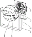
图1为本实用新型提出一种提高矿石冷却除湿的装置的立体结构示意图;Fig. 1 is the three-dimensional structure schematic diagram that the utility model proposes a kind of device that improves ore cooling dehumidification;
图2为本实用新型提出一种提高矿石冷却除湿的装置的第一网罩机构和第二网罩机构结构示意图;Fig. 2 is a structural schematic diagram of the first mesh cover mechanism and the second mesh cover mechanism of a device for improving ore cooling and dehumidification proposed by the utility model;
图3为本实用新型提出一种提高矿石冷却除湿的装置的第一网罩机构内部结构示意图;Fig. 3 is a schematic diagram of the internal structure of the first net cover mechanism of a device for improving ore cooling and dehumidification proposed by the utility model;
图4为本实用新型提出一种提高矿石冷却除湿的装置的第一网罩机构和第二网罩机构侧面剖视图。Fig. 4 is a side sectional view of the first net cover mechanism and the second net cover mechanism of a device for improving ore cooling and dehumidification proposed by the utility model.
图例说明:illustration:
1、U形架;2、电机;21、安装板;3、风机;31、支撑柱;1. U-shaped frame; 2. Motor; 21. Mounting plate; 3. Fan; 31. Support column;
4、第一网罩机构;41、第一上球罩;42、第一下球罩;43、锁扣板;44、转动筒;45、传动柱;46、被动柱;47、第一铰链;48、齿轮;49、定位杆;4. The first mesh cover mechanism; 41. The first upper ball cover; 42. The first lower ball cover; 43. The lock plate; 44. The rotating cylinder; 45. The transmission column; 46. The passive column; 47. The first hinge ; 48, gear; 49, positioning rod;
5、第二网罩机构;51、第二上球罩;52、第二下球罩;53、第二铰链;54、限位环;55、环形齿板。5. The second net cover mechanism; 51. The second upper ball cover; 52. The second lower ball cover; 53. The second hinge; 54. The limit ring; 55. The ring tooth plate.
具体实施方式detailed description
为了能够更清楚地理解本实用新型的上述目的、特征和优点,下面结合附图和实施例对本实用新型做进一步说明。需要说明的是,在不冲突的情况下,本申请的实施例及实施例中的特征可以相互组合。In order to understand more clearly the above purpose, features and advantages of the utility model, the utility model will be further described below in conjunction with the accompanying drawings and embodiments. It should be noted that, in the case of no conflict, the embodiments of the present application and the features in the embodiments can be combined with each other.
在下面的描述中阐述了很多具体细节以便于充分理解本实用新型,但是,本实用新型还可以采用不同于在此描述的其他方式来实施,因此,本实用新型并不限于下面公开说明书的具体实施例的限制。In the following description, a lot of specific details have been set forth in order to fully understand the utility model, but the utility model can also be implemented in other ways that are different from those described here. Therefore, the utility model is not limited to the specific details of the following disclosure EXAMPLE LIMITATIONS.
实施例1,如图1-4所示,本实用新型提供了一种提高矿石冷却除湿的装置,包括风机3,风机3的底端固定连接有两个支撑柱31,风机3的外侧设置有U形架1,U形架1的顶端两内侧壁之间设置有第一网罩机构4,第一网罩机构4包括第一上球罩41,第一上球罩41的底端设置有第一下球罩42,第一上球罩41和第一下球罩42之间设置有第一铰链47,第一上球罩41通过第一铰链47与第一下球罩42之间活动铰接,第一上球罩41与第一下球罩42的外侧壁均固定连接有锁扣板43,第一下球罩42的外侧壁位于U形架1的两侧壁位置处均固定连接有转动筒44,U形架1的外侧壁固定连接有安装板21,安装板21的顶端固定连接有电机2,电机2的输出端贯穿U形架1的侧壁并固定连接有传动柱45,传动柱45与转动筒44之间固定连接,U形架1背离电机2的内侧壁固定连接有被动柱46,被动柱46与转动筒44之间转动连接,第一网罩机构4的内部设置有第二网罩机构5,风机3与第一网罩机构4位于同一高度位置,将第一上球罩41翻转半圈,将需要冷却除湿的矿石放置在第一网罩机构4的内部,并再次翻转第一上球罩41半圈,使用锁将两个合并的锁扣板43之间固定,避免第一上球罩41与第一下球罩42之间再次分离,启动电机2,电机2的输出端带动传动柱45转动,使传动柱45带动固定连接的转动筒44转动,另一侧转动筒44与被动柱46之间转动,被动柱46相对U形架1静止,实现了电机2带动第一网罩机构4转动,同时启动风机3,风机3将冷气流向第一网罩机构4吹来,使第一网罩机构4内部的矿石一边竖直翻转,一边通过冷气流除湿,使矿石的外表面各个位置都能充分除湿,同时第一网罩机构4相对空气转动,也能充分的利用转动流动的空气进行除湿,使矿石的除湿效果更好。Embodiment 1, as shown in Figure 1-4, the utility model provides a kind of device that improves ore cooling dehumidification, comprises fan 3, and the bottom end of fan 3 is fixedly connected with two supporting columns 31, and the outside of fan 3 is provided with U-shaped frame 1, the first net cover mechanism 4 is arranged between the top two inner walls of the U-shaped frame 1, the first net cover mechanism 4 includes the first upper ball cover 41, and the bottom end of the first upper ball cover 41 is provided with The first lower dome cover 42, the first upper dome cover 41 and the first lower dome cover 42 are provided with a first hinge 47, the first upper dome cover 41 moves between the first hinge 47 and the first lower dome cover 42 Hinged, the outer side walls of the first upper ball cover 41 and the first lower ball cover 42 are fixedly connected with the locking plate 43, and the outer side walls of the first lower ball cover 42 are fixedly connected at the two side walls of the U-shaped frame 1 There is a rotating cylinder 44, the outer wall of the U-shaped frame 1 is fixedly connected with a mounting plate 21, the top of the mounting plate 21 is fixedly connected with a motor 2, and the output end of the motor 2 runs through the side wall of the U-shaped frame 1 and is fixedly connected with a transmission column 45 , the transmission column 45 is fixedly connected with the rotating cylinder 44, and the inner side wall of the U-shaped frame 1 away from the motor 2 is fixedly connected with a passive column 46, which is rotationally connected between the passive column 46 and the rotating cylinder 44, and the inside of the first mesh cover mechanism 4 The second net cover mechanism 5 is provided, the fan 3 is located at the same height as the first net cover mechanism 4, the first upper ball cover 41 is turned half a circle, and the ore that needs to be cooled and dehumidified is placed inside the first net cover mechanism 4 , and turn over the first upper dome cover 41 half a turn again, use a lock to fix the two combined locking plates 43 to avoid separation between the first upper dome cover 41 and the first lower dome cover 42 again, and start the motor 2 , the output end of the motor 2 drives the transmission column 45 to rotate, so that the transmission column 45 drives the fixedly connected rotating cylinder 44 to rotate, and the other side rotates between the rotating cylinder 44 and the passive column 46, and the passive column 46 is stationary relative to the U-shaped frame 1, realizing The motor 2 drives the first net cover mechanism 4 to rotate, and starts the fan 3 at the same time, and the fan 3 blows the cold air to the first net cover mechanism 4, so that the ore in the first net cover mechanism 4 is turned vertically while passing through the cold air flow. Dehumidification can fully dehumidify all positions on the outer surface of the ore. At the same time, the first
如图3所示,第二网罩机构5包括第二上球罩51,第二上球罩51的顶端设置有第二下球罩52,第二上球罩51与第二下球罩52之间设置有第二铰链53,第二上球罩51通过第二铰链53与第二下球罩52之间活动铰接,第二下球罩52的外侧壁中心位置处固定连接有环形齿板55,第二下球罩52的外侧壁位于环形齿板55的上方固定连接有限位环54,传动柱45的侧壁固定连接有齿轮48,齿轮48与环形齿板55之间相互啮合,第一下球罩42的内侧壁中心位置处均匀固定多个定位杆49,定位杆49与限位环54之间滑动连接,第一下球罩42的顶面对应圆形的半径为第二下球罩52的顶面对应圆形的半径的一点三倍,第二上球罩51与第二下球罩52的相邻一侧均固定连接有永磁铁,将第一网罩机构4内部的第二上球罩51翻转打开,将矿石放置在第二网罩机构5的内部,并合并第二上球罩51与第二下球罩52,通过第二上球罩51与第二下球罩52之间的永磁铁固定,齿轮48与下方的环形齿板55之间啮合,传动柱45转动时,带动齿轮48转动,齿轮48转动带动环形齿板55移动,由于环形齿板55通过第二下球罩52被几个定位杆49之间限位,所以第二下球罩52只能绕着第二网罩机构5的中心转动,使环形齿板55在平面上转动,实现了电机2启动时,一边带动第一网罩机构4在竖直方向转动,一边带动内部的第二网罩机构5在第一网罩机构4的内部水平转动,实现了第一网罩机构4内矿石全方位翻转,使风机3对矿石的冷却效果更加明显。As shown in Figure 3, the second
本装置的使用方法及工作原理:启动电机2,电机2的输出端带动传动柱45转动,传动柱45带动转动筒44转动,电机2带动第一网罩机构4转动,启动风机3,风机3将冷气吹向第一网罩机构4,传动柱45转动时,带动齿轮48转动,齿轮48转动带动环形齿板55移动,使环形齿板55在平面上转动,第二网罩机构5在第一网罩机构4的内部水平转动,使第二网罩机构5内部矿石各个角度都能经过风机3冷气流除湿冷却。The use method and working principle of this device: start the
以上所述,仅是本实用新型的较佳实施例而已,并非是对本实用新型作其它形式的限制,任何熟悉本专业的技术人员可能利用上述揭示的技术内容加以变更或改型为等同变化的等效实施例应用于其它领域,但是凡是未脱离本实用新型技术方案内容,依据本实用新型的技术实质对以上实施例所作的任何简单修改、等同变化与改型,仍属于本实用新型技术方案的保护范围。The above is only a preferred embodiment of the utility model, and is not intended to limit the utility model in other forms. Any skilled person who is familiar with this profession may use the technical content disclosed above to change or remodel it into an equivalent change. The equivalent embodiments are applied to other fields, but any simple modifications, equivalent changes and modifications made to the above embodiments according to the technical essence of the present invention without departing from the content of the technical solution of the present utility model still belong to the technical solution of the present utility model scope of protection.
Claims (7)
Priority Applications (1)
| Application Number | Priority Date | Filing Date | Title |
|---|---|---|---|
| CN202222179596.9U CN218155195U (en) | 2022-08-18 | 2022-08-18 | Device for improving cooling and dehumidifying of ore |
Applications Claiming Priority (1)
| Application Number | Priority Date | Filing Date | Title |
|---|---|---|---|
| CN202222179596.9U CN218155195U (en) | 2022-08-18 | 2022-08-18 | Device for improving cooling and dehumidifying of ore |
Publications (1)
| Publication Number | Publication Date |
|---|---|
| CN218155195U true CN218155195U (en) | 2022-12-27 |
Family
ID=84551170
Family Applications (1)
| Application Number | Title | Priority Date | Filing Date |
|---|---|---|---|
| CN202222179596.9U Expired - Fee Related CN218155195U (en) | 2022-08-18 | 2022-08-18 | Device for improving cooling and dehumidifying of ore |
Country Status (1)
| Country | Link |
|---|---|
| CN (1) | CN218155195U (en) |
-
2022
- 2022-08-18 CN CN202222179596.9U patent/CN218155195U/en not_active Expired - Fee Related
Similar Documents
| Publication | Publication Date | Title |
|---|---|---|
| CN203709212U (en) | Food drier | |
| CN110913623A (en) | Wisdom public security fortune dimension control box with box environmental control mechanism | |
| CN208419530U (en) | It is a kind of for molecular sieve molded drying unit | |
| CN209484966U (en) | One seed ginseng silkworm piece tablet heated-air circulation roaster | |
| CN107388775A (en) | A kind of cloth drying plant of weaving | |
| CN107677052B (en) | Chrysanthemum dewatering drying-machine convenient to material loading | |
| CN213578530U (en) | Building material drying device | |
| CN209820068U (en) | Multilayer cellular-type drying device of cereal processing usefulness | |
| CN207610480U (en) | A kind of apparatus for airing herbal medicine | |
| CN209459362U (en) | A kind of interior powder automatic drier recycled of hot gas | |
| CN207113507U (en) | A kind of dryer for ceramic tile embryo of silkworms | |
| CN209121175U (en) | Fast-drying device is used in a kind of processing of Moringa tea | |
| CN108917349A (en) | A kind of Chinese medicine dehumidification equipment | |
| CN221234838U (en) | Sand and stone aggregate conveying device | |
| CN112378212A (en) | Tealeaves stirring drying device based on thing networked control | |
| CN207626481U (en) | A kind of tea tedding device | |
| CN215909640U (en) | Electric automatization dampproof device | |
| CN207172564U (en) | A kind of sheath gumming device | |
| CN113101220A (en) | Traditional Chinese medicine pill making machine with dampness removing mechanism and traditional Chinese medicine pill making process | |
| CN210552494U (en) | Air drying equipment for plastic plate processing | |
| CN206911749U (en) | Clear device at the beginning of a kind of feed | |
| CN219781521U (en) | Tobacco drying system device of air source heat pump | |
| CN201575674U (en) | Static continuous dryer | |
| CN220931643U (en) | Tea dehumidification device | |
| CN207643479U (en) | A kind of master-batch drying device that drying effect is good |
Legal Events
| Date | Code | Title | Description |
|---|---|---|---|
| GR01 | Patent grant | ||
| GR01 | Patent grant | ||
| TR01 | Transfer of patent right | ||
| TR01 | Transfer of patent right |
Effective date of registration: 20231218 Address after: No. 36 Qilin Avenue, Gaoxin District, Donghai County, Lianyungang City, Jiangsu Province, 222300 Patentee after: Donghai Silicon Industry (Jiangsu) Technology Co.,Ltd. Address before: 222399 West of Weixing River, north of Qilin Avenue, West District, Donghai Development Zone, Lianyungang City, Jiangsu Province Patentee before: Jiangsu Hailiyuan Quartz Scientific Co.,Ltd. |
|
| CF01 | Termination of patent right due to non-payment of annual fee |
Granted publication date: 20221227 |