CN218293473U - Drilling equipment is used in exploration - Google Patents
Drilling equipment is used in exploration Download PDFInfo
- Publication number
- CN218293473U CN218293473U CN202222844720.9U CN202222844720U CN218293473U CN 218293473 U CN218293473 U CN 218293473U CN 202222844720 U CN202222844720 U CN 202222844720U CN 218293473 U CN218293473 U CN 218293473U
- Authority
- CN
- China
- Prior art keywords
- plate
- transmission shaft
- drilling
- motor
- scraper
- Prior art date
- Legal status (The legal status is an assumption and is not a legal conclusion. Google has not performed a legal analysis and makes no representation as to the accuracy of the status listed.)
- Expired - Fee Related
Links
- 238000005553 drilling Methods 0.000 title claims abstract description 60
- 230000005540 biological transmission Effects 0.000 claims abstract description 40
- 239000002689 soil Substances 0.000 abstract description 26
- 230000000694 effects Effects 0.000 abstract description 10
- 238000009825 accumulation Methods 0.000 abstract description 4
- 238000000034 method Methods 0.000 description 4
- 230000009286 beneficial effect Effects 0.000 description 2
- 238000003756 stirring Methods 0.000 description 2
- 230000007812 deficiency Effects 0.000 description 1
- 238000001514 detection method Methods 0.000 description 1
- 238000010586 diagram Methods 0.000 description 1
- 238000011835 investigation Methods 0.000 description 1
Images

Landscapes
- Earth Drilling (AREA)
Abstract
本实用新型公开了一种勘探用钻孔装置,包括支撑座,支撑座上设置有支杆,支杆的顶部设置有顶板,顶板上设置有气缸,气缸的输出端连接有第一电机,第一电机的输出端连接有传动轴,传动轴远离第一电机的一端设置有钻孔组件,支撑座上活动设置有弹性伸缩板,弹性伸缩板与传动轴之间设置有连接杆,弹性伸缩板的底部设置有刮板,刮板上连接有套管,套管与传动轴同轴设置。本实用新型便于对钻孔时旋出的泥土进行拨动,使其远离钻孔区域,避免其在钻孔上侧堆积,导致出现钻杆上移后泥土回填入钻孔内的情况,从而保证钻孔的效果。

The utility model discloses a drilling device for exploration, which comprises a support seat, a support rod is arranged on the support seat, a top plate is arranged on the top of the support rod, an air cylinder is arranged on the top plate, and a first motor is connected to the output end of the air cylinder. The output end of a motor is connected with a transmission shaft, and the end of the transmission shaft away from the first motor is provided with a drilling assembly, and an elastic expansion plate is movable on the support base, and a connecting rod is arranged between the elastic expansion plate and the transmission shaft, and the elastic expansion plate A scraper is arranged at the bottom of the scraper, a casing is connected to the scraper, and the casing is arranged coaxially with the transmission shaft. The utility model is convenient to move the soil unscrewed during drilling, so as to keep it away from the drilling area, avoiding its accumulation on the upper side of the drilling hole, resulting in the situation that the soil is backfilled into the drilling hole after the drilling rod is moved up, thereby Guarantee the effect of drilling.
Description
技术领域technical field
本实用新型涉及勘探技术领域,具体地说,涉及一种勘探用钻孔装置。The utility model relates to the technical field of exploration, in particular to a drilling device for exploration.
背景技术Background technique
地质勘探即是通过各种手段、方法对地质进行勘查、探测,确定合适的持力层,根据持力层的地基承载力,确定基础类型,计算基础参数的调查研究活动。在勘探过程中需要对土层进行钻孔操作。Geological prospecting is the investigation and research activity of conducting geological exploration and detection through various means and methods, determining the appropriate bearing layer, determining the foundation type and calculating the foundation parameters according to the foundation bearing capacity of the bearing layer. During the exploration process, the soil layer needs to be drilled.
但在钻孔过程中,破碎的泥土容易聚集在钻杆的周围,并在钻孔区域上侧堆积,尤其是螺旋钻钻孔的使用,在钻杆上移后,上侧堆积的泥土会有部分掉落在钻孔内,影响钻孔效果。However, during the drilling process, the broken soil tends to gather around the drill pipe and accumulate on the upper side of the drilling area, especially the use of auger drilling. After the drill pipe is moved up, the soil accumulated on the upper side will have Part of it falls into the drilling hole, affecting the drilling effect.
实用新型内容Utility model content
(一)解决的技术问题(1) Solved technical problems
针对现有技术的不足,本实用新型的目的在于提供一种勘探用钻孔装置,便于对钻孔时旋出的泥土进行拨动,使其远离钻孔区域,避免其在钻孔上侧堆积,导致出现钻杆上移后泥土回填入钻孔内的情况,从而保证钻孔的效果。Aiming at the deficiencies of the prior art, the purpose of this utility model is to provide a drilling device for exploration, which is convenient to move the soil that is unscrewed during drilling, so as to keep it away from the drilling area and avoid its accumulation on the upper side of the drilling hole. , resulting in the backfilling of the soil into the borehole after the drill pipe is moved up, so as to ensure the effect of the borehole.
(二)技术方案(2) Technical solution
本为实现上述目的,本实用新型提供如下技术方案,一种勘探用钻孔装置所采用的技术方案是:包括支撑座,所述支撑座上设置有支杆,所述支杆的顶部设置有顶板,所述顶板上设置有气缸,所述气缸的输出端连接有第一电机,所述第一电机的输出端连接有传动轴,所述传动轴远离第一电机的一端设置有钻孔组件,所述支撑座上活动设置有弹性伸缩板,所述弹性伸缩板与传动轴之间设置有连接杆,所述弹性伸缩板的底部设置有刮板,所述刮板上连接有套管,所述套管与传动轴同轴设置。In order to achieve the above object, the utility model provides the following technical solution, the technical solution adopted by a drilling device for exploration is: comprising a support seat, a support rod is provided on the support seat, and the top of the support rod is provided with A top plate, the top plate is provided with a cylinder, the output end of the cylinder is connected to a first motor, the output end of the first motor is connected to a transmission shaft, and the end of the transmission shaft away from the first motor is provided with a drilling assembly , an elastic telescopic plate is movably arranged on the support base, a connecting rod is arranged between the elastic telescopic plate and the transmission shaft, a scraper is arranged at the bottom of the elastic telescopic plate, and a casing is connected to the scraper, The sleeve is arranged coaxially with the transmission shaft.
作为优选方案,所述钻孔组件包括与传动轴相连的钻杆,所述钻杆外侧固设有螺旋叶片。As a preferred solution, the drilling assembly includes a drill rod connected with a transmission shaft, and a helical blade is fixed on the outer side of the drill rod.
作为优选方案,所述传动轴滑动设置在连接杆上,所述连接杆上开设有与传动轴相配合的凹孔,所述凹孔内壁连接有固定条,所述传动轴上开设有与固定条相配合的固定槽。As a preferred solution, the transmission shaft is slidably arranged on the connecting rod, and the connecting rod is provided with a concave hole matched with the transmission shaft, the inner wall of the concave hole is connected with a fixing strip, and the transmission shaft is provided with a Fitting slots for strips.
作为优选方案,所述支撑座的底部开设有环形槽,所述环形槽内滑动设置有滑块,所述滑块与弹性伸缩板固定相连。As a preferred solution, an annular groove is opened at the bottom of the support seat, and a slider is slidably arranged in the annular groove, and the slider is fixedly connected with the elastic telescopic plate.
作为优选方案,所述弹性伸缩板上设置有第二电机,所述第二电机的输出端穿过弹性伸缩板并连接有转动轴,所述转动轴上设置有拨动板,所述拨动板与刮板活动相抵。As a preferred solution, a second motor is arranged on the elastic expansion plate, the output end of the second motor passes through the elastic expansion plate and is connected to a rotating shaft, and a toggle plate is arranged on the rotating shaft, and the toggle plate The plate counteracts the scraper activity.
作为优选方案,所述拨动板包括与转动轴相连的壳体,所述壳体内滑动连接有活动板,所述活动板与壳体内壁之间设置有弹性元件。As a preferred solution, the toggle plate includes a housing connected to the rotating shaft, a movable plate is slidably connected in the housing, and an elastic element is arranged between the movable plate and the inner wall of the housing.
作为优选方案,所述支撑座上开设有通孔,所述第一电机活动设置在通孔内。As a preferred solution, a through hole is opened on the support base, and the first motor is movably arranged in the through hole.
(三)有益效果(3) Beneficial effects
与现有技术相比,本实用新型提供了一种勘探用钻孔装置,具备以下有益效果:Compared with the prior art, the utility model provides a drilling device for exploration, which has the following beneficial effects:
1、通过刮板的转动,使刮板对钻孔组件旋出的泥土进行拨动,使其在离心力的作用下远离钻孔区域,避免其在钻孔上侧堆积,导致出现钻杆上移后泥土回填入钻孔内的情况,从而保证钻孔的效果。1. Through the rotation of the scraper, the scraper moves the soil unscrewed by the drilling assembly to keep it away from the drilling area under the action of centrifugal force, avoiding its accumulation on the upper side of the drill hole, resulting in the upward movement of the drill pipe After the soil is backfilled into the borehole, the effect of the borehole is guaranteed.
2、本实用新型中拨动板包括壳体以及与壳体弹性设置的活动板,由于拨动板以转动轴为圆心进行转动,其活动轨迹是圆形,当其从刮板左端逆时针转动时,活动板初始时与地面接触,在拨动板转动至与弹性伸缩板呈平行状态的过程中,活动板会逐渐收缩进入壳体内,避免由于拨动板长度不可调,导致拨动板与地面接触后无法继续转动,影响其对泥土的拨动效果,保证其实用性通过刮板对泥土推动的同时,弹性伸缩板上设置的拨动板可对刮板刮动的泥土进行拨动,进一步加快泥土远离钻孔的速度,提高工作效率。2. In the utility model, the toggle plate includes a shell and a movable plate elastically arranged with the shell. Since the toggle plate rotates with the rotation axis as the center of a circle, its moving track is circular. When it rotates counterclockwise from the left end of the scraper When the movable plate is initially in contact with the ground, the movable plate will gradually shrink into the shell when the toggle plate rotates to be parallel to the elastic expansion plate, so as to avoid the unadjustable length of the toggle plate from causing the toggle plate to be in contact with the elastic expansion plate After the ground is in contact, it cannot continue to rotate, which affects its effect on the soil and ensures its practicability. While pushing the soil through the scraper, the toggle plate set on the elastic expansion plate can move the soil scraped by the scraper. Further speed up the speed of soil moving away from the drilling hole, and improve work efficiency.
附图说明Description of drawings
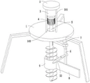
图1为本实用新型的结构示意图一;Fig. 1 is a structural representation one of the utility model;
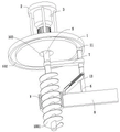
图2为本实用新型的结构示意图二;Fig. 2 is the structural representation two of the utility model;
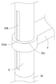
图3为本实用新型的传动轴与连接杆的结构示意图;Fig. 3 is the structural representation of transmission shaft and connecting rod of the present utility model;
图4为本实用新型的钻孔组件的结构示意图;Fig. 4 is the structural representation of the drilling assembly of the present utility model;
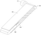
图5为本实用新型的拨动板的剖面结构示意图。Fig. 5 is a schematic cross-sectional structure diagram of the toggle plate of the present invention.
图中:1、支撑座;101、支杆;102、环形槽;103、通孔;2、顶板;3、气缸;4、第一电机;5、传动轴;501、固定槽;6、弹性伸缩板;7、连接杆;701、凹孔;7011、固定条;8、刮板;9、套管;10、钻杆;1001、螺旋叶片;11、滑块;12、第二电机;121、转动轴;13、拨动板;131、壳体;132、活动板;133、弹性元件。In the figure: 1, support seat; 101, pole; 102, annular groove; 103, through hole; 2, top plate; 3, cylinder; 4, first motor; 5, transmission shaft; 501, fixed groove; 6, elasticity Telescopic plate; 7, connecting rod; 701, recessed hole; 7011, fixed strip; 8, scraper; 9, casing; 10, drill pipe; 1001, spiral blade; 11, slider; 12, second motor; , rotating shaft; 13, toggle plate; 131, housing; 132, movable plate; 133, elastic element.
具体实施方式detailed description
下面结合附图和实施例对本实用新型的实施方式作进一步详细描述。以下实施例用于说明本实用新型,但不能用来限制本实用新型的范围。The implementation of the present utility model will be further described in detail below in conjunction with the accompanying drawings and examples. The following examples are used to illustrate the utility model, but cannot be used to limit the scope of the utility model.
在本实用新型的描述中,除非另有说明,“多个”的含义是两个或两个以上;术语“上”、“下”、“左”、“右”、“内”、“外”、“前端”、“后端”、“头部”、“尾部”等指示的方位或位置关系为基于附图所示的方位或位置关系,仅是为了便于描述本实用新型和简化描述,而不是指示或暗示所指的装置或元件必须具有特定的方位、以特定的方位构造和操作,因此不能理解为对本实用新型的限制。此外,术语“第一”、“第二”、“第三”等仅用于描述目的,而不能理解为指示或暗示相对重要性。In the description of the present utility model, unless otherwise specified, the meaning of "multiple" is two or more; the terms "upper", "lower", "left", "right", "inner", "outer" ", "front end", "rear end", "head", "tail", etc. indicate the orientation or positional relationship based on the orientation or positional relationship shown in the accompanying drawings, and are only for the convenience of describing the utility model and simplifying the description. It does not indicate or imply that the device or element referred to must have a specific orientation, be constructed and operate in a specific orientation, and therefore should not be construed as limiting the present invention. In addition, the terms "first", "second", "third", etc. are used for descriptive purposes only and should not be construed as indicating or implying relative importance.
在本实用新型的描述中,需要说明的是,除非另有明确的规定和限定,术语“相连”、“连接”应做广义理解,例如,可以是固定连接,也可以是可拆卸连接,或一体地连接;可以是机械连接,也可以是电连接;可以是直接相连,也可以通过中间媒介间接相连。对于本领域的普通技术人员而言,可以具体情况理解上述术语在本实用新型中的具体含义。In the description of the present utility model, it should be noted that unless otherwise specified and limited, the terms "connected" and "connected" should be understood in a broad sense, for example, it can be a fixed connection or a detachable connection, or Integratively connected; it can be mechanically or electrically connected; it can be directly connected or indirectly connected through an intermediary. Those of ordinary skill in the art can understand the specific meanings of the above terms in the present utility model in specific situations.
请参阅图1-4,本实用新型:一种勘探用钻孔装置,包括支撑座1,支撑座1上设置有支杆101,支杆101的顶部设置有顶板2,顶板2上设置有气缸3,气缸3的输出端连接有第一电机4,第一电机4的输出端连接有传动轴5,传动轴5远离第一电机4的一端设置有钻孔组件,支撑座1上活动设置有弹性伸缩板6,弹性伸缩板6与传动轴5之间设置有连接杆7,弹性伸缩板6的底部设置有刮板8,刮板8上连接有套管9,套管9与传动轴5同轴设置。Please refer to Figures 1-4, the utility model: a drilling device for exploration, including a
具体的,使用该装置进行钻孔时,将装置放置在待钻孔的位置,此时弹性伸缩板6底部连接的刮板8通过套管9与钻孔地面接触,套管9与第一电机4的输出轴处于同一轴线,随后控制气缸3和第一电机4运行,使钻孔组件下移并开始钻孔作业,在钻孔过程中,钻孔内的泥土被输送出钻孔并越过套管9散落在地面上,第一电机4运行时带动传动轴5驱动钻孔组件旋转钻孔,传动轴5通过连接杆7带动弹性伸缩板6旋转,弹性伸缩板6带动刮板8以套管9中心轴线为圆心进行转动,使刮板8对钻孔组件旋出的泥土进行拨动,使其在离心力的作用下远离钻孔区域,避免其在钻孔上侧堆积,导致出现钻孔组件上移后泥土回填入钻孔内的情况,从而保证钻孔的效果。Specifically, when using the device for drilling, the device is placed at the position to be drilled. At this time, the
请参阅图1和图4,作为本实用新型优选的技术方案,钻孔组件包括与传动轴5相连的钻杆10,钻杆10外侧固设有螺旋叶片1001。Referring to Fig. 1 and Fig. 4, as a preferred technical solution of the present invention, the drilling assembly includes a
具体的,钻孔组件工作时,钻杆10在传动轴5的传动作用下转动,使钻杆10带动螺旋叶片1001进行螺旋钻孔作业,钻孔时泥土向上输送至钻孔外。Specifically, when the drilling assembly is working, the
请参阅图1-3,作为本实用新型优选的技术方案,传动轴5滑动设置在连接杆7上,连接杆7上开设有与传动轴5相配合的凹孔701,凹孔701内壁连接有固定条7011,传动轴5上开设有与固定条7011相配合的固定槽501。Please refer to Fig. 1-3, as the preferred technical solution of the present invention, the
具体的,传动轴5随第一电机4在气缸3的作用下上下位移,使传动轴5的固定槽501与连接杆7上的固定条7011相对滑动,且传动轴5在转动时通过固定条7011带动连接杆7转动,进而使弹性伸缩板6转动。Specifically, the
请参阅图3,作为本实用新型优选的技术方案,支撑座1的底部开设有环形槽102,环形槽102内滑动设置有滑块11,滑块11与弹性伸缩板6固定相连。Please refer to FIG. 3 , as a preferred technical solution of the present invention, an
具体的,传动轴5通过连接杆7带动弹性伸缩板6转动时,弹性伸缩板6通过滑块11滑动在环形槽102内,提高其移动的稳定性。Specifically, when the
请参阅图1-2,作为本实用新型优选的技术方案,弹性伸缩板6上设置有第二电机12,第二电机12的输出端穿过弹性伸缩板6并连接有转动轴121,转动轴121上设置有拨动板13,拨动板13与刮板8活动相抵。Please refer to Fig. 1-2, as the preferred technical scheme of the present utility model, the
具体的,通过刮板8对泥土推动的同时,控制第二电机12运行,使第二电机12的输出端通过传动轴5带动拨动板13旋转,使拨动板13可对刮板8刮动的泥土进行拨动,进一步加快泥土远离钻孔的速度,提高工作效率。Specifically, while the soil is pushed by the
请参阅图2和图5,作为本实用新型优选的技术方案,拨动板13包括与转动轴121相连的壳体131,壳体131内滑动连接有活动板132,活动板132与壳体131内壁之间设置有弹性元件133。Referring to Fig. 2 and Fig. 5, as a preferred technical solution of the present invention, the
具体的,拨动板13包括壳体131以及与壳体131弹性设置的活动板132,由于拨动板13以转动轴121为圆心进行转动,其活动轨迹是圆形,当其从刮板8左端逆时针转动时,活动板132初始时与地面接触,在拨动板13转动至与弹性伸缩板6呈平行状态的过程中,活动板132会逐渐收缩进入壳体131内,避免由于拨动板13长度不可调,导致拨动板13与地面接触后无法继续转动,影响其对泥土的拨动效果,保证其实用性。Specifically, the
请参阅图1-2,作为本实用新型优选的技术方案,支撑座1上开设有通孔103,第一电机4活动设置在通孔103内。Please refer to Fig. 1-2, as a preferred technical solution of the present invention, a through
具体的,气缸3驱动第一电机4下移时,第一电机4通过通孔103穿过支撑座1。Specifically, when the
本实用新型的工作原理是:将装置放置在待钻孔的位置,此时弹性伸缩板6底部连接的刮板8通过套管9与钻孔地面接触,套管9与第一电机4的输出轴处于同一轴线,随后控制气缸3和第一电机4运行,使钻孔组件下移并开始钻孔作业,使钻杆10带动螺旋叶片1001进行螺旋钻孔作业,钻孔时泥土被输送出钻孔并越过套管9散落在地面上,传动轴5通过连接杆7带动弹性伸缩板6旋转,弹性伸缩板6带动刮板8以套管9中心轴线为圆心进行转动,使刮板8对钻孔组件旋出的泥土进行拨动,使其在离心力的作用下远离钻孔区域,避免其在钻孔上侧堆积,导致出现钻孔组件上移后泥土回填入钻孔内的情况,从而保证钻孔的效果,且刮板8对泥土推动的同时,控制第二电机12运行,使第二电机12的输出端通过传动轴5带动拨动板13旋转,使拨动板13可对刮板8刮动的泥土进行拨动,进一步加快泥土远离钻孔的速度,提高工作效率。The working principle of the utility model is: place the device at the position to be drilled, at this time, the
最后应当说明的是,以上实施例仅用以说明本实用新型的技术方案,而非对本实用新型保护范围的限制,尽管参照较佳实施例对本实用新型作了详细地说明,本领域的普通技术人员应当理解,可以对本实用新型的技术方案进行修改或者等同替换,而不脱离本实用新型技术方案的实质和范围。Finally, it should be noted that the above embodiments are only used to illustrate the technical solutions of the present utility model, rather than limiting the protection scope of the present utility model. Although the utility model has been described in detail with reference to the preferred embodiments, those skilled in the art Personnel should understand that the technical solution of the utility model can be modified or equivalently replaced without departing from the essence and scope of the technical solution of the utility model.
Claims (7)
Priority Applications (1)
| Application Number | Priority Date | Filing Date | Title |
|---|---|---|---|
| CN202222844720.9U CN218293473U (en) | 2022-10-27 | 2022-10-27 | Drilling equipment is used in exploration |
Applications Claiming Priority (1)
| Application Number | Priority Date | Filing Date | Title |
|---|---|---|---|
| CN202222844720.9U CN218293473U (en) | 2022-10-27 | 2022-10-27 | Drilling equipment is used in exploration |
Publications (1)
| Publication Number | Publication Date |
|---|---|
| CN218293473U true CN218293473U (en) | 2023-01-13 |
Family
ID=84809356
Family Applications (1)
| Application Number | Title | Priority Date | Filing Date |
|---|---|---|---|
| CN202222844720.9U Expired - Fee Related CN218293473U (en) | 2022-10-27 | 2022-10-27 | Drilling equipment is used in exploration |
Country Status (1)
| Country | Link |
|---|---|
| CN (1) | CN218293473U (en) |
Cited By (1)
| Publication number | Priority date | Publication date | Assignee | Title |
|---|---|---|---|---|
| CN119981682A (en) * | 2025-03-20 | 2025-05-13 | 浙江振硕岩土工程有限公司 | A down-the-hole drilling rig |
-
2022
- 2022-10-27 CN CN202222844720.9U patent/CN218293473U/en not_active Expired - Fee Related
Cited By (1)
| Publication number | Priority date | Publication date | Assignee | Title |
|---|---|---|---|---|
| CN119981682A (en) * | 2025-03-20 | 2025-05-13 | 浙江振硕岩土工程有限公司 | A down-the-hole drilling rig |
Similar Documents
| Publication | Publication Date | Title |
|---|---|---|
| CN212201999U (en) | A kind of oil well pipeline wax cleaning device | |
| CN118111746A (en) | A rock sample collection device for mining exploration | |
| CN220231008U (en) | Rock sampling device for geological environment | |
| CN118757095A (en) | A hole expander for geological exploration field work | |
| CN210920811U (en) | Bridge surveys support for equipment | |
| CN218454735U (en) | Logging instrument for petroleum geological exploration | |
| CN216284377U (en) | A kind of soil sampling equipment for civil engineering | |
| CN211448577U (en) | Drilling mud solid-liquid separation equipment | |
| CN118584554A (en) | A geothermal detection device for geological exploration | |
| CN217872771U (en) | Movable colliery geological drilling device | |
| CN211950340U (en) | Positive enlarger of horizontal directional drill is adopted in oil exploration exploitation | |
| CN221879307U (en) | Multifunctional geological exploration drill bit | |
| CN211115779U (en) | Off tracking device is prevented with probing to rock core probing | |
| CN212154656U (en) | A geology-specific reaming device | |
| CN211898301U (en) | A soil borrowing device with an adjustable angle | |
| CN209935892U (en) | A positioning drilling equipment for civil engineering construction | |
| CN217845688U (en) | Soil property sampling device for homeland resources | |
| CN207847529U (en) | A kind of calcareous sand roadbed sampling drilling equipment | |
| CN222084558U (en) | A high stability feeding device for underground mine filling slurry | |
| CN216741976U (en) | Adjustable water pump base | |
| CN221859970U (en) | Device for sampling coal mine tunneling interface | |
| CN223756037U (en) | A probe that can be used for measuring soil and rock settlement | |
| CN219299228U (en) | An exploration drilling machine | |
| CN219977819U (en) | Geological sample sampling device | |
| CN219316923U (en) | well drilling device |
Legal Events
| Date | Code | Title | Description |
|---|---|---|---|
| GR01 | Patent grant | ||
| GR01 | Patent grant | ||
| CF01 | Termination of patent right due to non-payment of annual fee |
Granted publication date: 20230113 |
|
| CF01 | Termination of patent right due to non-payment of annual fee |