CN218479727U - Sliding door with multiple rotating mechanisms - Google Patents
Sliding door with multiple rotating mechanisms Download PDFInfo
- Publication number
- CN218479727U CN218479727U CN202222800670.4U CN202222800670U CN218479727U CN 218479727 U CN218479727 U CN 218479727U CN 202222800670 U CN202222800670 U CN 202222800670U CN 218479727 U CN218479727 U CN 218479727U
- Authority
- CN
- China
- Prior art keywords
- push
- rotating
- pull
- opening
- door
- Prior art date
- Legal status (The legal status is an assumption and is not a legal conclusion. Google has not performed a legal analysis and makes no representation as to the accuracy of the status listed.)
- Active
Links
- 230000007246 mechanism Effects 0.000 title claims abstract description 78
- 230000003014 reinforcing effect Effects 0.000 claims abstract description 15
- 238000009434 installation Methods 0.000 claims abstract description 9
- 239000003292 glue Substances 0.000 claims abstract description 4
- 238000005034 decoration Methods 0.000 claims description 6
- 238000003466 welding Methods 0.000 abstract description 2
- 230000002787 reinforcement Effects 0.000 description 4
- 230000004075 alteration Effects 0.000 description 1
- 230000009286 beneficial effect Effects 0.000 description 1
- 238000010586 diagram Methods 0.000 description 1
- 238000012986 modification Methods 0.000 description 1
- 230000004048 modification Effects 0.000 description 1
- 238000006467 substitution reaction Methods 0.000 description 1
Images



Landscapes
- Hinges (AREA)
Abstract
The utility model discloses a multiple rotary mechanism's push-and-pull door relates to the push-and-pull door. The utility model provides a multiple rotary mechanism's push-and-pull door, including indoor wall body, indoor wall body bottom is equipped with the bottom ground mat, and indoor wall body top is equipped with indoor ceiling, indoor wall body inboard is installed the second grade push-and-pull frame through second grade rotation link mechanism, and the second grade push-and-pull frame inboard is installed the door body through glue and is supported the inner panel, one-level rotation link mechanism is installed to second grade push-and-pull frame opposite side, and one-level rotation link mechanism installs one-level push-and-pull frame in one side, the inboard welding of one-level push-and-pull frame has the inboard installation pole, and inboard installation pole both sides are equipped with the interior reinforcing plate of door, one-level push-and-pull frame one side screw mounting has outside hand pull, and one-and-pull frame one side has seted up the lock body mounting groove, install between the second grade rotation link mechanism and rotate the hinge. The utility model provides a push-and-pull door rotating part easy damage, can't realize multistage pivoted problem.
Description
Technical Field
The utility model relates to a push-and-pull door specifically is a multiple rotary mechanism's push-and-pull door.
Background
The sliding door is a common household door and can be pushed and pulled; along with the development of the technology and the diversification of decoration means, the key for realizing the push-pull of the sliding door is the rotation of the door body, and a rotating part is needed for realizing the rotation.
The push-and-pull door of present stage has push-and-pull door rotating part easy to damage, can't realize multistage pivoted problem. Accordingly, those skilled in the art have provided a multi-rotation sliding door to solve the above problems of the prior art.
SUMMERY OF THE UTILITY MODEL
An object of the utility model is to provide a multiple rotary mechanism's push-and-pull door to solve the problem that proposes among the above-mentioned background art.
In order to achieve the above object, the utility model provides a following technical scheme: the utility model provides a multiple rotary mechanism's push-and-pull door, includes indoor wall body, indoor wall body bottom is equipped with the bottom ground mat, and indoor wall body top is equipped with indoor ceiling, indoor wall body inboard is installed the second grade push-and-pull frame through second grade rotation link mechanism, and second grade push-and-pull frame inboard installs the door body through glue and supports the inner panel, one-level rotation link mechanism is installed to second grade push-and-pull frame opposite side, and one-level rotation link mechanism installs one-level push-and-pull frame in one side, the inboard welding of one-level push-and-pull frame has the inboard installation pole, and inboard installation pole both sides are equipped with the interior reinforcing plate, one-level push-and-pull frame one side screw mounting has outside hand power, and one-level push-and-pull frame one side has seted up the lock body mounting groove, install the rotation hinge between the second grade rotation link mechanism, it is big to have rotary part intensity, can realize the advantage of multistage push-and pull.
Preferably, the inner side of the indoor wall body is provided with an inner mounting plate, so that the mounting of the two-stage rotating connecting rod mechanism can be realized.
Preferably, the door plate decoration is arranged on the inner side of the door body support inner plate, so that the decoration of the door body support inner plate can be improved.
Preferably, a lock body mounting hole is formed in one side of the lock body mounting groove, so that the door lock can be conveniently mounted.
Preferably, the second-stage rotating connecting rod mechanism is internally provided with a rotating mounting frame, the end part of the rotating mounting frame is provided with an end part rotating pin, and the inner side of the end part rotating pin is provided with a first opening and closing rod and an opening and closing reinforcing rod in a matching manner, so that the opening and closing of the rotating connecting rod mechanism can be realized.
Preferably, the end parts of the first opening and closing rod and the opening and closing reinforcing rod are provided with connecting rotating pins, and the other side of the connecting rotating pins is provided with a second opening and closing rod, so that the internal reinforcement of the rotating link mechanism can be realized.
Preferably, the second-stage rotating connecting rod mechanism and the first-stage rotating connecting rod mechanism are fixedly arranged on one side wall surface of the first-stage push-pull frame and one side wall surface of the second-stage push-pull frame through a rotating mounting frame and screws, so that the first-stage push-pull frame and the second-stage push-pull frame can rotate conveniently.
Compared with the prior art, the beneficial effects of the utility model are that:
(1) The utility model provides a push-and-pull door of multiple rotary mechanism, install parts such as one-level rotation link mechanism and one-level push-and-pull frame through the push-and-pull door that gives a multiple rotary mechanism, in order to realize multistage push-and-pull in the scheme, adopt two push-and-pull frames, install second grade rotation link mechanism in installation inner panel one side, and second grade rotation link mechanism installs second grade push-and-pull frame one side, second grade push-and-pull frame opposite side rotates link mechanism and one-level push-and-pull frame fix with screw through one-level, realize the reinforcement rotation of both sides push-and-pull door frame through rotating the hinge between the rotation link mechanism at upper and lower both ends, and then accomplish the second grade push-and-pull function of whole push-and-pull door, the problem that the push-and-pull rotary part easily destroys has been solved.
(2) The utility model provides a multiple rotary mechanism's push-and-pull door, install parts such as rotation mounting bracket and tip rotating pin through the push-and-pull door that gives a multiple rotary mechanism, in order to improve push-and-pull rotary mechanism's intensity, except adopting traditional single pivot formula to rotate the hinge, still adopted rotation link mechanism, both sides are equipped with two rotation mounting brackets in rotating link mechanism, and rotate the mounting bracket inboard and install first opening and shutting pole and opening and shutting anchor strut through the tip rotating pin respectively, and install the second opening and shutting pole in the connection rotating pin of tip, the opening and shutting of whole mechanism is realized through first opening and shutting pole and second opening and shutting pole and connection rotating pin, and the anchor strut that opens and shuts conducts and disperses the driving force, prevent that inside driving force from too concentrating on first opening and shutting pole and second opening and shutting pole, improve whole rotation link mechanism's the intensity that can bear the push-and-pull force, the unable multistage pivoted problem of realizing of push-and-pull door of having solved.
Drawings
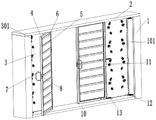
Fig. 1 is a schematic structural view of the present invention;
fig. 2 is an isometric view of the structure of the middle sliding door according to the present invention;
fig. 3 is a schematic view of a partial structure of a middle-stage and second-stage sliding door according to the present invention;
FIG. 4 is a partial schematic view of the structure of the lock body mounting groove of the present invention;
fig. 5 is a schematic diagram of the second-stage rotating link mechanism of the structure of the second-stage rotating link mechanism of the present invention.
In the figure: 1. an indoor wall body; 101. installing an inner plate; 2. an indoor ceiling; 3. the door body supports the inner plate; 301. decorating the door plate; 4. a first-stage push-pull frame; 5. a rod is arranged on the inner side; 6. an inner door reinforcement panel; 7. an outer hand pull handle; 8. a lock body mounting groove; 801. a lock body mounting hole; 9. a secondary push-pull frame; 10. a bottom floor mat; 11. rotating the hinge; 12. a secondary rotating link mechanism; 1201. an end rotation pin; 1202. rotating the mounting rack; 1203. a first opening and closing lever; 1204. connecting a rotating pin; 1205. a second opening and closing lever; 1206. opening and closing the reinforcing rod; 13. a first-stage rotating link mechanism.
Detailed Description
The technical solutions in the embodiments of the present invention will be described clearly and completely with reference to the accompanying drawings in the embodiments of the present invention, and it is obvious that the described embodiments are only some embodiments of the present invention, not all embodiments. Based on the embodiments in the present invention, all other embodiments obtained by a person skilled in the art without creative work belong to the protection scope of the present invention.
Please refer to fig. 1-4, in an embodiment of the present invention, a multi-rotating mechanism sliding door, including an indoor wall 1, a bottom ground mat 10 is disposed at the bottom of the indoor wall 1, and an indoor ceiling 2 is disposed at the top of the indoor wall 1, a second-level sliding frame 9 is mounted on the inner side of the indoor wall 1 through a second-level rotating link mechanism 12, a door supporting inner plate 3 is mounted on the inner side of the second-level sliding frame 9 through glue, a first-level rotating link mechanism 13 is mounted on the other side of the second-level sliding frame 9, a first-level sliding frame 4 is mounted on one side of the first-level rotating link mechanism 13, an inner side mounting rod 5 is welded on the inner side of the first-level sliding frame 4, inner side reinforcing plates 6 are disposed on both sides of the inner side mounting rod 5, an outer side hand pull handle 7 is mounted on one side of the first-level sliding frame 4 through a screw, a lock body mounting groove 8 is disposed on one side of the first-level sliding frame 4, a rotating hinge 11 is mounted between the second-level rotating link mechanisms 12, and the rotating component has a high strength and can realize the advantage of multi-level sliding.
The inner side of the indoor wall body 1 is provided with an inner mounting plate 101, so that the mounting of the secondary rotating connecting rod mechanism 12 can be realized; the door plate decoration 301 is arranged on the inner side of the door body supporting inner plate 3, so that the decoration of the door body supporting inner plate 3 can be improved; a lock body mounting hole 801 is formed in one side of the lock body mounting groove 8, so that the door lock can be conveniently mounted; a rotating mounting frame 1202 is arranged on the inner side of the secondary rotating link mechanism 12, an end rotating pin 1201 is mounted at the end of the rotating mounting frame 1202, a first opening and closing rod 1203 and an opening and closing reinforcing rod 1206 are mounted on the inner side of the end rotating pin 1201 in a matched mode, and the opening and closing of the rotating link mechanism can be achieved; the ends of the first opening and closing rod 1203 and the opening and closing reinforcing rod 1206 are provided with connecting rotating pins 1204, and the other side of the connecting rotating pins 1204 is provided with a second opening and closing rod 1205, so that the internal reinforcement of the rotating link mechanism can be realized; the secondary rotating link mechanism 12 and the primary rotating link mechanism 13 are fixedly mounted on one side wall surfaces of the primary push-pull frame 4 and the secondary push-pull frame 9 through the rotating mounting frame 1202 and screws, so that the primary push-pull frame 4 and the secondary push-pull frame 9 can rotate conveniently.
The working principle is as follows: a main body of a sliding door of a multi-rotation mechanism comprises a secondary rotation connecting rod mechanism 12, a primary sliding frame 4, a secondary sliding frame 9 and the like, and the device is different from a traditional sliding door and has the advantages that the strength of a rotating part is high, and multi-stage sliding can be realized; in the scheme, in order to realize multi-stage push-pull, double push-pull frames are adopted, a second-stage rotating connecting rod mechanism 12 is installed on one side of an installation inner plate 101, a second-stage push-pull frame 9 is installed on one side of the second-stage rotating connecting rod mechanism 12, the other side of the second-stage push-pull frame 9 is fixed with a first-stage push-pull frame 4 through a first-stage rotating connecting rod mechanism 13 through screws, and the rotating connecting rod mechanisms at the upper end and the lower end realize the reinforced rotation of push-pull door frames at two sides through rotating hinges 11, so that the second-stage push-pull function of the whole push-pull door is further completed; in order to improve the strength of the push-pull rotating mechanism, besides the traditional single-rotating-shaft rotating hinge 11, a rotating link mechanism is also adopted, two rotating installation frames 1202 are arranged on two sides in the rotating link mechanism, a first opening-closing rod 1203 and an opening-closing reinforcing rod 1206 are respectively installed on the inner sides of the rotating installation frames 1202 through end rotating pins 1201, a second opening-closing rod 1205 is installed in a connecting rotating pin 1204 at the end part, the opening and closing of the whole mechanism are realized through the first opening-closing rod 1203, the second opening-closing rod 1205 and the connecting rotating pin 1204, the opening-closing reinforcing rod 1206 conducts and disperses driving force, the internal driving force is prevented from being excessively concentrated on the first opening-closing rod 1203 and the second opening-closing rod 1205, and the strength of the push-pull force of the whole rotating link mechanism is improved.
Although embodiments of the present invention have been shown and described, it will be appreciated by those skilled in the art that various changes, modifications, substitutions and alterations can be made in these embodiments without departing from the principles and spirit of the invention, the scope of which is defined in the appended claims and their equivalents.
Claims (10)
1. The utility model provides a multiple rotary mechanism's push-and-pull door, includes indoor wall body (1), its characterized in that: the indoor wall comprises an indoor wall body (1), a bottom ground mat (10) is arranged at the bottom of the indoor wall body (1), an indoor ceiling (2) is arranged at the top of the indoor wall body (1), a secondary push-pull frame (9) is mounted on the inner side of the indoor wall body (1) through a secondary rotating link mechanism (12), a door body supporting inner plate (3) is mounted on the inner side of the secondary push-pull frame (9) through glue, a primary rotating link mechanism (13) is mounted on the other side of the secondary push-pull frame (9), a primary push-pull frame (4) is mounted on one side of the primary rotating link mechanism (13), an inner mounting rod (5) is welded on the inner side of the primary push-pull frame (4), door inner reinforcing plates (6) are arranged on two sides of the inner mounting rod (5), an outer hand pull handle (7) is mounted on one side of the primary push-pull frame (4) through screws, a lock body (8) is arranged on one side of the primary push-pull frame (4), and a rotating hinge (11) is mounted between the secondary rotating link mechanisms (12); the inner side of the secondary rotating link mechanism (12) is provided with a rotating mounting frame (1202), an end rotating pin (1201) is mounted at the end of the rotating mounting frame (1202), and a first opening and closing rod (1203) and an opening and closing reinforcing rod (1206) are mounted on the inner side of the end rotating pin (1201) in a matched mode.
2. The sliding door of multi-rotary mechanism of claim 1, wherein: and an installation inner plate (101) is arranged on the inner side of the indoor wall body (1).
3. A multi-rotary-mechanism sliding door according to claim 1 or 2, wherein: the inner side of the door body supporting inner plate (3) is provided with a door panel decoration (301).
4. A multi-rotary-mechanism sliding door according to claim 1 or 2, wherein: and a lock body mounting hole (801) is formed in one side of the lock body mounting groove (8).
5. A multi-rotary mechanism sliding door according to claim 3, wherein: and a lock body mounting hole (801) is formed in one side of the lock body mounting groove (8).
6. The sliding door with multiple rotating mechanisms according to claim 1, 2 or 5, characterized in that: and a connecting rotating pin (1204) is arranged at the end parts of the first opening and closing rod (1203) and the opening and closing reinforcing rod (1206), and a second opening and closing rod (1205) is arranged on the other side of the connecting rotating pin (1204).
7. A multi-rotary mechanism sliding door according to claim 3, wherein: and a connecting rotating pin (1204) is installed at the end parts of the first opening and closing rod (1203) and the opening and closing reinforcing rod (1206), and a second opening and closing rod (1205) is installed at the other side of the connecting rotating pin (1204).
8. The sliding door of multi-rotary mechanism according to claim 4, wherein: and a connecting rotating pin (1204) is arranged at the end parts of the first opening and closing rod (1203) and the opening and closing reinforcing rod (1206), and a second opening and closing rod (1205) is arranged on the other side of the connecting rotating pin (1204).
9. The sliding door of multi-rotation mechanism according to claim 1, 2, 5, 7 or 8, wherein: the secondary rotating connecting rod mechanism (12) and the primary rotating connecting rod mechanism (13) are fixedly arranged on one side wall surface of the primary push-pull frame (4) and one side wall surface of the secondary push-pull frame (9) through the rotating mounting frame (1202) and screws.
10. A multi-rotary mechanism sliding door according to claim 3, wherein: the secondary rotating connecting rod mechanism (12) and the primary rotating connecting rod mechanism (13) are fixedly arranged on one side wall surface of the primary push-pull frame (4) and one side wall surface of the secondary push-pull frame (9) through the rotating mounting frame (1202) and screws.
Priority Applications (1)
| Application Number | Priority Date | Filing Date | Title |
|---|---|---|---|
| CN202222800670.4U CN218479727U (en) | 2022-10-24 | 2022-10-24 | Sliding door with multiple rotating mechanisms |
Applications Claiming Priority (1)
| Application Number | Priority Date | Filing Date | Title |
|---|---|---|---|
| CN202222800670.4U CN218479727U (en) | 2022-10-24 | 2022-10-24 | Sliding door with multiple rotating mechanisms |
Publications (1)
| Publication Number | Publication Date |
|---|---|
| CN218479727U true CN218479727U (en) | 2023-02-14 |
Family
ID=85169313
Family Applications (1)
| Application Number | Title | Priority Date | Filing Date |
|---|---|---|---|
| CN202222800670.4U Active CN218479727U (en) | 2022-10-24 | 2022-10-24 | Sliding door with multiple rotating mechanisms |
Country Status (1)
| Country | Link |
|---|---|
| CN (1) | CN218479727U (en) |
-
2022
- 2022-10-24 CN CN202222800670.4U patent/CN218479727U/en active Active
Similar Documents
| Publication | Publication Date | Title |
|---|---|---|
| CN218479727U (en) | Sliding door with multiple rotating mechanisms | |
| JP4066188B2 (en) | Skeletal structural member with door | |
| CN206707426U (en) | A kind of horizontal drawing can adjust the gate dead bolt of mounting distance | |
| CN220434576U (en) | Frame type flood-proof door | |
| CN223634518U (en) | A concealed hinge structure | |
| CN206379514U (en) | A kind of jumping type floor receptacle | |
| CN222083761U (en) | A kind of movable board house at construction site | |
| CN212454038U (en) | Gooseneck type hinge for automobile tail door | |
| KR20020044359A (en) | Hinge structure for back door | |
| CN215520481U (en) | Aluminum alloy hinge for metal door and window | |
| CN215859708U (en) | Bridge cut-off aluminum alloy window reinforced structure | |
| CN219034418U (en) | Left rotary pin structure of door and window hinge for building engineering | |
| CN207348716U (en) | A kind of mounting structure of metallic door | |
| CN218541951U (en) | Arc-shaped hidden door installation structure | |
| CN223739102U (en) | A reinforced structure for communication towers | |
| CN220667326U (en) | High lighting rate energy-saving type side-hung window section bar | |
| CN205805237U (en) | A kind of outside door handle structure | |
| CN221322127U (en) | Energy storage box access door opening and closing structure | |
| CN116575836B (en) | Aluminum profile window with high stability | |
| CN220022656U (en) | A kind of combined solar photovoltaic installation frame | |
| CN219374473U (en) | Aluminum alloy cabinet body structure | |
| CN222350510U (en) | Heavy inward-opening backward-rotation 90-degree invisible hinge | |
| CN222391257U (en) | Multi-open type module house combined window | |
| CN217779246U (en) | 180-degree double-shaft hinge mechanism between front piece and small door of liquid transport box | |
| CN115492444B (en) | Root opening control device and control method |
Legal Events
| Date | Code | Title | Description |
|---|---|---|---|
| GR01 | Patent grant | ||
| GR01 | Patent grant |