CN218905723U - Hook head adjusting mechanism and edge sealing equipment - Google Patents
Hook head adjusting mechanism and edge sealing equipment Download PDFInfo
- Publication number
- CN218905723U CN218905723U CN202223499683.9U CN202223499683U CN218905723U CN 218905723 U CN218905723 U CN 218905723U CN 202223499683 U CN202223499683 U CN 202223499683U CN 218905723 U CN218905723 U CN 218905723U
- Authority
- CN
- China
- Prior art keywords
- assembly
- hook head
- connecting rod
- swing rod
- adjusting mechanism
- Prior art date
- Legal status (The legal status is an assumption and is not a legal conclusion. Google has not performed a legal analysis and makes no representation as to the accuracy of the status listed.)
- Active
Links
Images


Landscapes
- Transmission Devices (AREA)
Abstract
本实用新型公开了一种钩头调节机构及封边设备,包括驱动组件、连杆组件和调节组件,连杆组件的第一端与驱动组件的驱动端连接;其中,连杆组件上铰接有第一摆杆;调节组件包括旋转主体,以及沿旋转主体的周向设置的若干个不同长度的调节螺杆;转动旋转主体,使其中一个调节螺杆与连杆组件的第二端抵接。工作时,转动旋转主体,使所需长度的调节螺杆转动至与连接组件相对应的位置,连杆组件带动第一摆杆摆动,通过第一摆杆的摆动来控制钩头的定位长度;本钩头调节机构能够通过相对应长度的调节螺杆来控制连杆组件的移动行程,从而起到控制钩头的定位长度的作用,提高对板材的定位精度,进而提高封边精度。

The utility model discloses a hook adjusting mechanism and edge sealing equipment, which comprises a driving assembly, a connecting rod assembly and an adjusting assembly, the first end of the connecting rod assembly is connected with the driving end of the driving assembly; wherein, the connecting rod assembly is hinged with The first swing rod; the adjusting assembly includes a rotating main body and several adjusting screw rods of different lengths arranged along the circumference of the rotating main body; the rotating main body is rotated so that one of the adjusting screw rods abuts against the second end of the connecting rod assembly. When working, turn the rotating main body to make the adjusting screw of the required length rotate to the position corresponding to the connecting assembly, the connecting rod assembly drives the first swing rod to swing, and the positioning length of the hook head is controlled by the swing of the first swing rod; The hook head adjustment mechanism can control the moving stroke of the connecting rod assembly through the adjustment screw rod of the corresponding length, so as to control the positioning length of the hook head, improve the positioning accuracy of the plate, and then improve the edge sealing accuracy.
Description
技术领域technical field
本实用新型涉及封边技术领域,尤其涉及一种钩头调节机构及封边设备。The utility model relates to the technical field of edge sealing, in particular to a hook adjusting mechanism and edge sealing equipment.
背景技术Background technique
封边作业是板式家具制造过程中的一道重要工序,封边质量的好坏直接影响产品的质量、价格和档次。通过封边可以很好地改善家具的外观质量,避免家具在运输和使用过程中边角部损坏、贴面层被掀起或剥落,同时可起到防水、封闭有害气体的释放和减少变形等作用。Edge banding is an important process in the manufacturing process of panel furniture. The quality of edge banding directly affects the quality, price and grade of products. The appearance quality of the furniture can be improved by sealing the edge, avoiding damage to the corners of the furniture during transportation and use, and the veneer layer being lifted or peeled off. At the same time, it can play the role of waterproofing, sealing the release of harmful gases and reducing deformation. .
现有技术中的封边设备的钩头定位机构,通过气缸推出钩头,由于气缸的行程是固定的,因此钩头出来的长度也是固定的,钩头定位长度不能调整,不能跟随板厚度变化,在对不同厚度的板材进行定位时,无法达到充分定位的效果,导致定位效果差,影响后续封边精度。The hook head positioning mechanism of the edge banding equipment in the prior art pushes out the hook head through the cylinder. Since the stroke of the cylinder is fixed, the length of the hook head coming out is also fixed. The hook head positioning length cannot be adjusted and cannot follow the change of the board thickness. , When positioning plates of different thicknesses, it is impossible to achieve sufficient positioning effect, resulting in poor positioning effect and affecting the subsequent edge banding accuracy.
鉴于此,需要对现有技术中的封边设备加以改进,以解决钩头定位长度固定,定位效果差的技术问题。In view of this, it is necessary to improve the edge banding equipment in the prior art to solve the technical problem of fixed hook head positioning length and poor positioning effect.
实用新型内容Utility model content
本实用新型的目的在于提供一种钩头调节机构及封边设备,解决以上的技术问题。The purpose of this utility model is to provide a hook adjustment mechanism and edge sealing equipment to solve the above technical problems.
为达此目的,本实用新型采用以下技术方案:For this purpose, the utility model adopts the following technical solutions:
一种钩头调节机构,包括:A hook adjustment mechanism, comprising:
驱动组件;drive components;
连杆组件,所述连杆组件的第一端与所述驱动组件的驱动端连接;其中,所述连杆组件上铰接有第一摆杆;A connecting rod assembly, the first end of the connecting rod assembly is connected to the driving end of the driving assembly; wherein, a first swing link is hinged on the connecting rod assembly;
调节组件,所述调节组件包括旋转主体,以及沿所述旋转主体的周向设置的若干个不同长度的调节螺杆;转动所述旋转主体,使其中一个所述调节螺杆与所述连杆组件的第二端抵接。An adjustment assembly, the adjustment assembly includes a rotating main body, and several adjusting screw rods of different lengths arranged along the circumference of the rotating main body; turning the rotating main body makes one of the adjusting screw rods and the connecting rod assembly The second end abuts.
可选的,所述调节组件还包括固定件,所述旋转主体的一端面开设有中心孔,所述固定件插接于所述中心孔内;Optionally, the adjustment assembly further includes a fixing piece, a central hole is opened on one end surface of the rotating body, and the fixing piece is inserted into the central hole;
所述旋转主体的外侧壁上开设有若干个与所述中心孔贯通的安装孔,所述安装孔内设有卡接组件,所述卡接组件的一端与所述固定件卡接。The outer wall of the rotating main body is provided with a plurality of mounting holes that communicate with the central hole, and a clamping assembly is provided in the mounting hole, and one end of the clamping assembly is clamped with the fixing member.
可选的,所述卡接组件包括弹性件和顶伸钢珠,所述弹性件的一端与所述旋转主体连接,另一端与所述顶伸钢珠连接,所述弹性件用于顶推所述顶伸钢珠伸入于所述中心孔内。Optionally, the clamping assembly includes an elastic member and a protruding steel ball, one end of the elastic member is connected to the rotating body, and the other end is connected to the protruding steel ball, and the elastic member is used to push the The protruding steel ball extends into the central hole.
可选的,所述第一摆杆远离所述连杆组件的一端开设有安装槽,所述安装槽内设有导向板。Optionally, an installation groove is opened at the end of the first swing rod away from the connecting rod assembly, and a guide plate is arranged in the installation groove.
可选的,所述第一摆杆的中部设有第一旋转销,所述第一摆杆转动连接于所述第一旋转销,所述驱动组件运行,以带动所述导向板绕所述第一旋转销转动。Optionally, a first rotation pin is provided in the middle of the first swing link, the first swing link is rotatably connected to the first rotation pin, and the driving assembly operates to drive the guide plate around the The first rotary pin rotates.
可选的,所述钩头调节机构还包括第二摆杆,所述第二摆杆的一端铰接于所述连杆组件上,另一端设有压轮。Optionally, the gib adjusting mechanism further includes a second swing rod, one end of which is hinged to the connecting rod assembly, and the other end is provided with a pressure wheel.
可选的,所述第二摆杆的中部设有第二旋转销,所述第二摆杆转动连接于第二旋转销,所述驱动组件运行,以带动压轮绕所述第二旋转销转动。Optionally, a second rotation pin is provided in the middle of the second swing rod, the second swing rod is rotatably connected to the second rotation pin, and the driving assembly operates to drive the pressure wheel to rotate around the second rotation pin turn.
可选的,所述驱动组件为驱动气缸,所述驱动气缸的活塞杆与所述连杆组件连接。Optionally, the driving assembly is a driving cylinder, and the piston rod of the driving cylinder is connected to the connecting rod assembly.
可选的,若干个所述调节螺杆的长度沿预设旋向依次减少或增加。Optionally, the lengths of several adjusting screws decrease or increase sequentially along the preset rotation direction.
一种封边设备,包括链节机构和如上所述的钩头调节机构,所述链节机构上滑动连接有钩头组件;An edge banding device, comprising a chain link mechanism and the hook adjustment mechanism as described above, the chain link mechanism is slidably connected with a hook assembly;
所述链节机构以带动所述钩头组件移动,使所述钩头组件与所述第一摆杆的一端相抵接。The chain link mechanism drives the hook assembly to move, so that the hook assembly abuts against one end of the first swing rod.
与现有技术相比,本实用新型具有以下有益效果:工作时,转动旋转主体,使所需长度的调节螺杆转动至与连接组件相对应的位置,驱动组件运行,以带动连杆组件沿其长度方向直线运动,连杆组件带动第一摆杆摆动,通过第一摆杆的摆动来控制钩头的定位长度;其中,连杆组件移动至预设位置时,连杆组件的第二端与调节螺杆相抵接,连杆组件无法继续移动,进而控制第一摆杆的摆动行程;本钩头调节机构能够通过相对应长度的调节螺杆来控制连杆组件的移动行程,从而起到控制钩头的定位长度的作用,提高对板材的定位精度,进而提高封边精度。Compared with the prior art, the utility model has the following beneficial effects: when working, the rotating main body is rotated to make the adjustment screw of the required length rotate to the position corresponding to the connecting assembly, and the driving assembly runs to drive the connecting rod assembly along its Linear movement in the length direction, the connecting rod assembly drives the first swing rod to swing, and the positioning length of the hook head is controlled by the swing of the first swing rod; wherein, when the connecting rod assembly moves to a preset position, the second end of the connecting rod assembly and the The adjusting screw rods are in contact with each other, and the connecting rod assembly cannot continue to move, thereby controlling the swing stroke of the first swing rod; the hook head adjusting mechanism can control the moving stroke of the connecting rod assembly through the adjusting screw rod of a corresponding length, thereby controlling the swing stroke of the hook head. The role of the positioning length, improve the positioning accuracy of the plate, and then improve the edge sealing accuracy.
附图说明Description of drawings
为了更清楚地说明本实用新型实施例或现有技术中的技术方案,下面将对实施例或现有技术描述中所需要使用的附图作简单地介绍,显而易见地,下面描述中的附图仅仅是本实用新型的一些实施例,对于本领域普通技术人员来讲,在不付出创造性劳动性的前提下,还可以根据这些附图获得其它的附图。In order to more clearly illustrate the technical solutions in the embodiments of the present invention or the prior art, the following will briefly introduce the accompanying drawings that need to be used in the description of the embodiments or the prior art. Obviously, the accompanying drawings in the following description These are only some embodiments of the present utility model, and those skilled in the art can also obtain other drawings according to these drawings without any creative effort.
本说明书附图所绘示的结构、比例、大小等,均仅用以配合说明书所揭示的内容,以供熟悉此技术的人士了解与阅读,并非用以限定本实用新型可实施的限定条件,故不具技术上的实质意义,任何结构的修饰、比例关系的改变或大小的调整,在不影响本实用新型所能产生的功效及所能达成的目的下,均应仍落在本实用新型所揭示的技术内容得能涵盖的范围内。The structures, proportions, sizes, etc. shown in the drawings of this specification are only used to cooperate with the content disclosed in the specification, for those who are familiar with this technology to understand and read, and are not used to limit the limited conditions that the utility model can be implemented. Therefore, there is no technical substantive meaning, and any modification of structure, change of proportional relationship or adjustment of size shall still fall within the scope of the utility model without affecting the effect and the purpose of the utility model. The disclosed technical content must be within the scope covered.
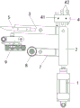
图1为本钩头调节机构的整体示意图;Fig. 1 is the overall schematic diagram of this gib adjustment mechanism;
图2为本钩头调节机构的驱动组件和连杆组件的主体结构示意图;Fig. 2 is a schematic diagram of the main structure of the driving assembly and the connecting rod assembly of the gib adjusting mechanism;
图3为本钩头调节机构的调节组件的结构示意图;Fig. 3 is a structural schematic diagram of the adjustment assembly of the gib adjustment mechanism;
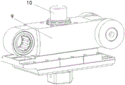
图4为本封边设备的链节机构和钩头组件的结构示意图。Fig. 4 is a structural schematic diagram of the chain link mechanism and hook assembly of the edge banding equipment.
图示说明:驱动组件1、连杆组件2、第一摆杆3、调节组件4、旋转主体41、调节螺杆42、固定件43、中心孔411、安装孔412、卡接组件44、弹性件441、顶伸钢珠442、导向板5、第一旋转销6、第二摆杆7、第二旋转销71、压轮8、链节机构9、钩头组件10。Illustration:
具体实施方式Detailed ways
为使得本实用新型的实用新型目的、特征、优点能够更加的明显和易懂,下面将结合本实用新型实施例中的附图,对本实用新型实施例中的技术方案进行清楚、完整地描述,显然,下面所描述的实施例仅仅是本实用新型一部分实施例,而非全部的实施例。基于本实用新型中的实施例,本领域普通技术人员在没有做出创造性劳动前提下所获得的所有其它实施例,都属于本实用新型保护的范围。In order to make the purpose, features and advantages of the utility model more obvious and easy to understand, the technical solutions in the utility model embodiment will be clearly and completely described below in conjunction with the accompanying drawings in the utility model embodiment, Apparently, the embodiments described below are only some of the embodiments of the present invention, but not all of them. Based on the embodiments of the present utility model, all other embodiments obtained by persons of ordinary skill in the art without making creative efforts belong to the scope of protection of the present utility model.
在本实用新型的描述中,需要理解的是,术语“上”、“下”、“顶”、“底”、“内”、“外”等指示的方位或位置关系为基于附图所示的方位或位置关系,仅是为了便于描述本实用新型和简化描述,而不是指示或暗示所指的装置或元件必须具有特定的方位、以特定的方位构造和操作,因此不能理解为对本实用新型的限制。需要说明的是,当一个组件被认为是“连接”另一个组件,它可以是直接连接到另一个组件或者可能同时存在居中设置的组件。In the description of the present utility model, it should be understood that the orientation or positional relationship indicated by the terms "upper", "lower", "top", "bottom", "inner" and "outer" are based on the The orientation or positional relationship is only for the convenience of describing the utility model and simplifying the description, but does not indicate or imply that the device or element referred to must have a specific orientation, be constructed and operated in a specific orientation, so it cannot be understood as a reference to the utility model. limits. It should be noted that when a component is considered to be "connected" to another component, it can be directly connected to the other component or there may be a centered component at the same time.
下面结合附图并通过具体实施方式来进一步说明本实用新型的技术方案。The technical scheme of the utility model will be further described below in conjunction with the accompanying drawings and through specific embodiments.
结合图1至图3所示,本实用新型实施例提供了一种钩头调节机构,包括:As shown in Figure 1 to Figure 3, the embodiment of the utility model provides a hook adjustment mechanism, including:
驱动组件1;
连杆组件2,所述连杆组件2的第一端与所述驱动组件1的驱动端连接;其中,所述连杆组件2上铰接有第一摆杆3;A
调节组件4,所述调节组件4包括旋转主体41,以及沿所述旋转主体41的周向设置的若干个不同长度的调节螺杆42;转动所述旋转主体41,使其中一个所述调节螺杆42与所述连杆组件2的第二端抵接。An
本实用新型的工作原理为:工作时,转动所述旋转主体41,使所需长度的调节螺杆42转动至与连接组件相对应的位置,驱动组件1运行,以带动连杆组件2沿其长度方向直线运动,连杆组件2带动第一摆杆3摆动,通过第一摆杆3的摆动来控制钩头的定位长度;其中,连杆组件2移动至预设位置时,连杆组件2的第二端与调节螺杆42相抵接,连杆组件2无法继续移动,进而控制第一摆杆3的摆动行程;相较于现有技术中的封边设备,本钩头调节机构能够通过相对应长度的调节螺杆42来控制连杆组件2的移动行程,从而起到控制钩头的定位长度的作用,提高对板材的定位精度,进而提高封边精度。The working principle of the utility model is: when working, rotate the rotating
在本实施例中,所述调节组件4还包括固定件43,所述旋转主体41的一端面开设有中心孔411,所述固定件43插接于所述中心孔411内;In this embodiment, the
所述旋转主体41的外侧壁上开设有若干个与所述中心孔411贯通的安装孔412,所述安装孔412内设有卡接组件44,所述卡接组件44的一端与所述固定件43卡接。The outer wall of the rotating
需要说明的是,通常本方案中的钩头调节机构是安装在封边设备的机架上的,其中,固定件43固定于机架上的预设位置,所述固定件43的一端插入于所述中心孔411内,然后卡接组件44伸入于中心孔411并与所述固定件43卡接,从而将旋转主体41固定于预设的角度和位置,以便于相对应长度的调节螺杆42能够抵住所述连杆组件2;It should be noted that, generally, the hook adjustment mechanism in this solution is installed on the frame of the edge banding equipment, wherein the
同时,卡接组件44通过卡接的方式来固定旋转主体41,即旋转主体41和固定件43为可拆卸连接的方式,以便于能够调整所述旋转主体41的角度。At the same time, the
具体说明的是,所述卡接组件44包括弹性件441和顶伸钢珠442,所述弹性件441的一端与所述旋转主体41连接,另一端与所述顶伸钢珠442连接,所述弹性件441用于顶推所述顶伸钢珠442伸入于所述中心孔411内。其中优选的方式,所述弹性件441为弹簧。Specifically, the
需要说明的是,本方案中的卡接方式为,通过弹簧顶推顶伸钢珠442来卡住固定件43;其中,顶伸钢珠442为部分卡接于固定件43上的卡接槽内,这样设置的优点在于,转动所述旋转主体41时,顶伸钢珠442会被向内顶推从而压缩弹性件441,此时,旋转主体41和固定件43分离,从而能够转动旋转件,旋转主体41转动至所需角度,弹簧顶推顶伸钢珠442来卡住固定件43;It should be noted that the clamping method in this solution is to clamp the fixing
本方案中的旋转主体41的外侧壁上开设有若干个安装孔412,其中优选的,若干个安装孔412分别与若干个调节螺杆42相对应。Several installation holes 412 are opened on the outer wall of the rotating
在本实施例中,所述第一摆杆3远离所述连杆组件2的一端开设有安装槽,所述安装槽内设有导向板5。In this embodiment, an installation groove is opened at the end of the
进一步说明的是,所述第一摆杆3的中部设有第一旋转销6,所述第一摆杆3转动连接于所述第一旋转销6,所述驱动组件1运行,以带动所述导向板5绕所述第一旋转销6转动。其中,第一旋转销6安装于机架上。It is further explained that, the middle part of the
所述驱动组件1运行以推动连杆组件2沿其长度方向直线运动,从而带动第一摆杆3的第一端绕第一旋转销6转动,进而带动所述导向板5绕所述第一旋转销6转动,通过导向板5的转动来推动钩头组件10伸出。The driving
在本实施例中,所述钩头调节机构还包括第二摆杆7,所述第二摆杆7的一端铰接于所述连杆组件2上,另一端设有压轮8。In this embodiment, the gib adjustment mechanism further includes a
进一步说明的是,所述第二摆杆7的中部设有第二旋转销71,所述第二摆杆7转动连接于第二旋转销71,所述驱动组件1运行,以带动压轮8绕所述第二旋转销71转动。It is further explained that a second
作为本实施例的一可选方案,所述驱动组件1为驱动气缸,所述驱动气缸的活塞杆与所述连杆组件2连接。通过调节组件4的设置,间接地限制了驱动气缸的活塞杆的移动行程。As an optional solution of this embodiment, the driving
作为本实施例的一优选方案,若干个所述调节螺杆42的长度沿预设旋向依次减少或增加。即若干个所述调节螺杆42的长度依次递增或递减,以便于能够快速挑选出所需要长度的调节螺杆42。As a preferred solution of this embodiment, the lengths of the several adjusting
实施例二:Embodiment two:
本实用新型还提供了一种封边设备,包括链节机构9和如实施例一所述的钩头调节机构,所述链节机构9上滑动连接有钩头组件10;The utility model also provides an edge banding device, which includes a
所述链节机构9以带动所述钩头组件10移动,使所述钩头组件10与所述第一摆杆3的一端相抵接。The
结合图4所示,本方案中的链节机构9(即链条)实际工作中为链条式转动,沿链节机构9上设有钩头组件10,钩头组件10可相对于链节机构9伸出或缩回,本方案通过第一摆杆3的一端(导向板5)来压合钩头组件10。In conjunction with shown in Figure 4, the chain link mechanism 9 (i.e. chain) in this program is a chain rotation in actual work, and a
以上所述,以上实施例仅用以说明本实用新型的技术方案,而非对其限制;尽管参照前述实施例对本实用新型进行了详细的说明,本领域的普通技术人员应当理解:其依然可以对前述各实施例所记载的技术方案进行修改,或者对其中部分技术特征进行等同替换;而这些修改或者替换,并不使相应技术方案的本质脱离本实用新型各实施例技术方案的精神和范围。As mentioned above, the above embodiments are only used to illustrate the technical solutions of the present utility model, and are not intended to limit it; although the utility model has been described in detail with reference to the foregoing embodiments, those of ordinary skill in the art should understand that: it still can Modifications are made to the technical solutions described in the foregoing embodiments, or equivalent replacements are made to some of the technical features; and these modifications or replacements do not make the essence of the corresponding technical solutions deviate from the spirit and scope of the technical solutions of the various embodiments of the present utility model .
Claims (10)
Priority Applications (1)
| Application Number | Priority Date | Filing Date | Title |
|---|---|---|---|
| CN202223499683.9U CN218905723U (en) | 2022-12-27 | 2022-12-27 | Hook head adjusting mechanism and edge sealing equipment |
Applications Claiming Priority (1)
| Application Number | Priority Date | Filing Date | Title |
|---|---|---|---|
| CN202223499683.9U CN218905723U (en) | 2022-12-27 | 2022-12-27 | Hook head adjusting mechanism and edge sealing equipment |
Publications (1)
| Publication Number | Publication Date |
|---|---|
| CN218905723U true CN218905723U (en) | 2023-04-25 |
Family
ID=86050092
Family Applications (1)
| Application Number | Title | Priority Date | Filing Date |
|---|---|---|---|
| CN202223499683.9U Active CN218905723U (en) | 2022-12-27 | 2022-12-27 | Hook head adjusting mechanism and edge sealing equipment |
Country Status (1)
| Country | Link |
|---|---|
| CN (1) | CN218905723U (en) |
-
2022
- 2022-12-27 CN CN202223499683.9U patent/CN218905723U/en active Active
Similar Documents
| Publication | Publication Date | Title |
|---|---|---|
| CN201010385Y (en) | Correcting roller with adjustable imaginary fulcrum | |
| CN209682495U (en) | A kind of load-bearing beam mould of adjustable deck-siding | |
| CN218905723U (en) | Hook head adjusting mechanism and edge sealing equipment | |
| CN118321483B (en) | Corner closely-spliced riveting equipment and closely-spliced riveting process of aluminum corrugated core composite plate | |
| CN211221143U (en) | A clamping tool with centering function | |
| CN219216583U (en) | Panel turnover device for wood floor processing | |
| CN220295607U (en) | Steel plate edge bending device | |
| CN107363192A (en) | Bar bending process equipment | |
| CN219201217U (en) | Paint film impact tester | |
| CN218109836U (en) | a welding device | |
| CN222387139U (en) | Timber perforating device with stabilizing mean | |
| CN224169661U (en) | A steering device for glass processing | |
| CN223483622U (en) | Auxiliary installation equipment for natural gas pipeline | |
| CN224129623U (en) | A board clamping mechanism for furniture production | |
| CN223557001U (en) | Window sash section bar corner cut stamping device | |
| CN222307042U (en) | Steel member stabilizes drilling equipment | |
| CN219528461U (en) | Steel construction rack assembles positioning mechanism | |
| CN223643572U (en) | Positioning device for flange fork shaft production | |
| CN223617551U (en) | Mechanical part clamp with self-adaptive clamping function | |
| CN223657233U (en) | A beveled corner hinged door production board beveling clamp | |
| CN223349611U (en) | Crimp locking device | |
| CN221135650U (en) | A jig for processing plate-shaped mechanical products | |
| CN222944223U (en) | Tensioner for unreeling steel belt | |
| CN222958533U (en) | Tensioning device pressure equipment frock | |
| CN219234213U (en) | Round cutting device for small straight-line sports car |
Legal Events
| Date | Code | Title | Description |
|---|---|---|---|
| GR01 | Patent grant | ||
| GR01 | Patent grant |