CN218977832U - Improved structure of mousetrap - Google Patents
Improved structure of mousetrap Download PDFInfo
- Publication number
- CN218977832U CN218977832U CN202223365193.XU CN202223365193U CN218977832U CN 218977832 U CN218977832 U CN 218977832U CN 202223365193 U CN202223365193 U CN 202223365193U CN 218977832 U CN218977832 U CN 218977832U
- Authority
- CN
- China
- Prior art keywords
- rocker
- outer end
- door
- wane
- cage
- Prior art date
- Legal status (The legal status is an assumption and is not a legal conclusion. Google has not performed a legal analysis and makes no representation as to the accuracy of the status listed.)
- Active
Links
- 230000000903 blocking effect Effects 0.000 claims abstract description 24
- 101000713935 Mus musculus Tudor domain-containing protein 7 Proteins 0.000 claims abstract description 4
- 238000004140 cleaning Methods 0.000 claims description 13
- 239000002184 metal Substances 0.000 claims description 4
- 239000000463 material Substances 0.000 claims description 3
- 210000001364 upper extremity Anatomy 0.000 abstract description 4
- 241000699666 Mus <mouse, genus> Species 0.000 description 27
- 241000700159 Rattus Species 0.000 description 8
- 241000699670 Mus sp. Species 0.000 description 7
- 230000005484 gravity Effects 0.000 description 3
- 230000009286 beneficial effect Effects 0.000 description 1
- 238000010586 diagram Methods 0.000 description 1
- 238000000034 method Methods 0.000 description 1
- 238000007789 sealing Methods 0.000 description 1
Images


Classifications
-
- Y—GENERAL TAGGING OF NEW TECHNOLOGICAL DEVELOPMENTS; GENERAL TAGGING OF CROSS-SECTIONAL TECHNOLOGIES SPANNING OVER SEVERAL SECTIONS OF THE IPC; TECHNICAL SUBJECTS COVERED BY FORMER USPC CROSS-REFERENCE ART COLLECTIONS [XRACs] AND DIGESTS
- Y02—TECHNOLOGIES OR APPLICATIONS FOR MITIGATION OR ADAPTATION AGAINST CLIMATE CHANGE
- Y02A—TECHNOLOGIES FOR ADAPTATION TO CLIMATE CHANGE
- Y02A50/00—TECHNOLOGIES FOR ADAPTATION TO CLIMATE CHANGE in human health protection, e.g. against extreme weather
- Y02A50/30—Against vector-borne diseases, e.g. mosquito-borne, fly-borne, tick-borne or waterborne diseases whose impact is exacerbated by climate change
Landscapes
- Catching Or Destruction (AREA)
Abstract
The utility model discloses an improved structure of a mouse trap. The novel mouse trapping cage comprises a cage body, wherein a mouse trapping inlet is formed in one end of the cage body, a door body which is opened and closed in a rotating mode is arranged at the position, corresponding to the mouse trapping inlet, of the cage body, a blocking portion is arranged at the outer side of the door body, the door body and the blocking portion are propped against each other to close the mouse trapping inlet, a first rocker is arranged in the cage body in a rotating mode, the door body is scratched by the first rocker, when the inner end of the first rocker is stressed to move downwards, the outer end of the first rocker is tilted to block the door body to open inwards, a second rocker is arranged between the outer end of the first rocker and the blocking portion in a rotating mode, when the outer end of the first rocker is stressed to move downwards, the inner end of the second rocker is driven to move downwards, the outer end of the second rocker is tilted, and the second rocker is blocked to open inwards. According to the mousetrap disclosed by the utility model, when the forelimbs of a mouse in the mousetrap body press the outer ends of the first warping plates, the second warping plates are driven to act so as to limit the door body to rotate inwards, and the outside mouse cannot push the door body to open, so that the mouse in the mousetrap body cannot escape.
Description
Technical Field
The utility model relates to an improved structure of a mouse trap.
Background
The existing mousetrap comprises a cage body, wherein a door body is arranged on one side of the cage body, the door body is controlled to be closed by a trigger device in the cage body, and when the mousetrap is used, a mouse enters the mousetrap and touches the trigger device, and the door body is closed to realize mousing. The mousetrap basically only can catch one mouse at a time, then the mouse needs to be taken out and the trigger device is reset, so that the mousetrap has low mousing efficiency.
Applicant discloses a mousetrap in prior patent 2022227370676, and it includes the first door body that the cage body and one-way open and shut set up, and the cage body passes through the internal open and shut of second stop device restriction first door to improve mousing efficiency. However, in the testing process, it was found that the forelimbs of the mice in the cage can pass over the second limiting device, and the second limiting device cannot limit the opening and closing of the first door body, so that the external mice can push the first door body open, and further the mice in the cage are separated, and the improvement is needed.
Disclosure of Invention
The utility model aims to provide a mousetrap with a more perfect closed post-mousetrap body.
The object of the present utility model is thus achieved.
The utility model provides a mousetrap improves structure, including the cage body that one end was equipped with the mouse trapping entrance, the cage body corresponds the mouse trapping entrance and is equipped with the door body that rotates to open and shut, the cage body corresponds the door body outside and is equipped with the blocking part, the door body offsets with blocking part in order to seal the mouse trapping entrance, the internal rotation of cage is provided with first wane, the door body is drawn first wane, when the internal atress of first wane moves down, first wane outer end perk blocking door body inwards opens, the cage body rotates between first wane outer end and blocking part and is provided with the second wane, when the external atress of first wane moves down, first wane outer end drives the internal downshifting of second wane, the external end perk of second wane, the second wane blocks the internal inwards opening of door.
The above technical solution can be further perfected as follows.
More specifically, under the normal state, first wane outer end and second wane inner are close, make door body bottom follow first wane and second wane on the slip.
More specifically, the inner gravity of second wane is less than second wane outer end, and under the normality, second wane outer end downwardly moving, the cage body is equipped with spacing portion in second wane outer end below, and second wane outer end offsets with spacing portion, makes the door body slide from the second wane.
More specifically, the second wane outer end is close to tip department and is equipped with the spacing groove, and when the second wane outer end perk and cage body support, the spacing inslot is arranged in to the door body bottom.
More specifically, the blocking part downwardly extending, when the outer end of the second seesaw is tilted to be propped against the cage body, the blocking part is arranged in the limiting groove, and the bottom of the door body is positioned between the inner side wall of the limiting groove and the blocking part.
More specifically, in normal state, the outer end of the first seesaw is inclined downward.
More specifically, the other end of the cage body is provided with a rat cleaning outlet, the cage body is provided with a plug door corresponding to the rat cleaning outlet, the side surface of the cage body is provided with a vertical slot corresponding to the rat cleaning outlet, and the plug door is plugged into the slot to seal the rat cleaning outlet.
More specifically, the cage body and the plug door are both made of plastic materials, and the inner side of the plug door is provided with a metal protection sheet.
The utility model has the following beneficial effects.
According to the mousetrap disclosed by the utility model, when the forelimbs of a mouse in the mousetrap body press the outer ends of the first warping plates, the second warping plates are driven to act so as to limit the door body to rotate inwards, and the outside mouse cannot push the door body to open, so that the mouse in the mousetrap body cannot escape. When the forelimbs of the mice in the cage body press down the inner ends of the first wanes, the inward rotation of the limiting door body can be limited. The sealing stability of the cage body is improved. The plug door is convenient for cleaning mice in the cage body, and the metal protection sheet is placed in the cage body, so that the mice in the cage body are destroyed by the plug door and escape from the mouse cleaning outlet.
Drawings
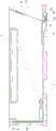
Fig. 1 is a schematic structural diagram of a first embodiment.
Fig. 2 is an exploded view of the first embodiment.
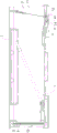
Fig. 3 is a schematic cross-sectional structure of the first embodiment (the first door is in a completely opened state).
Fig. 4 is a schematic cross-sectional structure of the first embodiment (the inner end of the first rocker is moved downward).
Fig. 5 is a schematic cross-sectional structure of the first embodiment (the outer end of the first rocker is moved downward).
Fig. 6 is a schematic view of the bottom structure of the first embodiment.
Detailed Description
The utility model is further described below with reference to the drawings and examples.
An embodiment I, see fig. 1-6, shows a mousetrap improvement structure, including a cage body 1, and a cage body 1 end is equipped with lures mouse entry 11, and a cage body 1 other end is equipped with clear mouse export 12. The cage body 1 is provided with a door body 2 corresponding to the mouse trapping inlet 11, the top of the door body 2 is rotationally connected with the cage body 1, the bottom of the cage body 1 is provided with a blocking part 13 corresponding to the outer side of the door body 2, and the door body 2 rotates towards the blocking part 13 under the action of gravity until the bottom of the door body 2 is propped against the blocking part 13 to seal the mouse trapping inlet 11.
The cage 1 is rotatably provided with a first rocker 3 and a second rocker 4, the second rocker 4 being located between the first rocker 3 and the blocking portion 13. In a normal state, the outer end of the first rocker 3 is arranged in a downward inclined mode, so that the door body 2 is scratched above the first rocker 3. Preferably, the inner and outer ends of the first rocker 3 are balanced.
The gravity of the inner end of the second rocker 4 is smaller than that of the outer end of the second rocker 4, the outer end of the second rocker 4 moves downwards in a normal state, a limiting part 14 is arranged below the outer end of the second rocker 4 in the cage body 1, and the outer end of the second rocker 4 abuts against the limiting part 14, so that the door body 2 slides over the second rocker 4. The outer end of the first rocker 3 is close to the inner end of the second rocker 4. Wherein, the outer end of the second seesaw 4 is provided with a limit groove 41 near the end. The blocking part 13 extends downwards, when the outer end of the second seesaw 4 is tilted to prop against the cage body 1, the blocking part 13 is arranged in the limiting groove 41, and the bottom of the door body 2 is positioned between the inner side wall of the limiting groove 41 and the blocking part 13.
The cage body 1 is provided with a plug door 5 corresponding to the rat cleaning outlet 12, the side surface of the cage body 1 is provided with a vertical slot 15 corresponding to the rat cleaning outlet 12, and the plug door 5 is inserted into the slot 15 to seal the rat cleaning outlet 12. The cage body 1 and the plug door 5 are both made of plastic materials, and a metal protection sheet 6 is arranged on the inner side of the plug door 5.
Of course, the cage body 1 of this embodiment is further provided with a triggering device 7, the triggering device 7 makes the door body 2 suspended, and the mouse trapping entrance 11 is completely opened. When a mouse enters the cage body 1 to trigger the trigger device 7, the door body 2 freely falls to be propped against the blocking part 13, and the mouse trapping inlet 11 is closed by the door body 2, so that the aim of trapping the mouse is fulfilled. At this time, the external mouse can still push the door body 2 to open, realize continuing the purpose that kills rats. The triggering device 7 is prior art and will not be described in detail in this application.
When the mouse in the cage body 1 moves towards the door body 2, if the mouse applies force to the inner end of the first rocker 3, the inner end of the first rocker 3 moves downwards, so that the outer end of the first rocker 3 is lifted, at the moment, the mouse is blocked by the outer end of the first rocker 3, the external mouse cannot push the door body 2 to open, and the mouse in the cage body 1 cannot escape outwards. If the mouse passes over the inner end of the first rocker 3 and downwards presses the outer end of the first rocker 3, the outer end of the first rocker 3 drives the inner end of the second rocker 4 to downwards move, the outer end of the second rocker 4 is lifted up to prop against the cage body 1, the bottom of the door body 2 is just placed in the limit groove 41, the outside mouse still cannot push the door body 2 to open, and the mouse in the cage body 1 cannot outwards escape.
The user can open the plug door 5 to clean the mice in the cage body 1 and clean the cage body 1.
Claims (8)
1. The utility model provides a mousetrap improves structure, including the cage body that one end was equipped with the mousetrap entry, the cage body corresponds the mousetrap entry and is equipped with the door body that rotates to open and shut, the cage body corresponds the door body outside and is equipped with the blocking part, the door body offsets with blocking part in order to seal the mousetrap entry, the internal rotation of cage is provided with first wane, the door body is drawn first wane, when the internal atress of first wane moves down, first wane outer end perk blocking door body inwards opens, characterized by, the cage body rotates between first wane outer end and blocking part and is provided with the second wane, when the external atress of first wane moves down, first wane outer end drives the internal downmovement of second wane, the external pere of second pere, the second wane blocks the internal inwards opening of door.
2. The improvement as set forth in claim 1 wherein the outer end of the first rocker and the inner end of the second rocker are normally biased against each other to allow the bottom of the door body to slide over the first rocker and the second rocker.
3. The improvement as set forth in claim 1 wherein the weight of the inner end of the second rocker is less than the weight of the outer end of the second rocker, the outer end of the second rocker moving downward in normal conditions, the cage being provided with a stop portion below the outer end of the second rocker, the outer end of the second rocker being adjacent the stop portion to allow the door to slide over the second rocker.
4. The improvement as set forth in claim 3 wherein the outer end of the second rocker is provided with a limiting groove near the end, and when the outer end of the second rocker is tilted up to abut against the cage, the bottom of the door is disposed in the limiting groove.
5. The improvement as set forth in claim 4 wherein the blocking portion extends downwardly and is disposed in the limiting slot when the outer end of the second rocker is tilted against the cage body, the bottom of the door body being disposed between the inner side wall of the limiting slot and the blocking portion.
6. The improved structure of the mouse trap as defined in any one of claims 1 to 5, wherein the outer end of the first rocker is inclined downward in a normal state.
7. The improved structure of the mouse trap according to claim 1, wherein the other end of the cage body is provided with a mouse cleaning outlet, the cage body is provided with a plug door corresponding to the mouse cleaning outlet, the side surface of the cage body is provided with a vertical slot corresponding to the mouse cleaning outlet, and the plug door is plugged into the slot to seal the mouse cleaning outlet.
8. The improved structure of the mousetrap according to claim 7, wherein the cage body and the plug door are both made of plastic materials, and a metal protection sheet is arranged on the inner side of the plug door.
Priority Applications (1)
| Application Number | Priority Date | Filing Date | Title |
|---|---|---|---|
| CN202223365193.XU CN218977832U (en) | 2022-12-15 | 2022-12-15 | Improved structure of mousetrap |
Applications Claiming Priority (1)
| Application Number | Priority Date | Filing Date | Title |
|---|---|---|---|
| CN202223365193.XU CN218977832U (en) | 2022-12-15 | 2022-12-15 | Improved structure of mousetrap |
Publications (1)
| Publication Number | Publication Date |
|---|---|
| CN218977832U true CN218977832U (en) | 2023-05-09 |
Family
ID=86190671
Family Applications (1)
| Application Number | Title | Priority Date | Filing Date |
|---|---|---|---|
| CN202223365193.XU Active CN218977832U (en) | 2022-12-15 | 2022-12-15 | Improved structure of mousetrap |
Country Status (1)
| Country | Link |
|---|---|
| CN (1) | CN218977832U (en) |
-
2022
- 2022-12-15 CN CN202223365193.XU patent/CN218977832U/en active Active
Similar Documents
| Publication | Publication Date | Title |
|---|---|---|
| JPH02503055A (en) | animal trap | |
| CN218977832U (en) | Improved structure of mousetrap | |
| CA1075281A (en) | Door latch control means for a dishwasher | |
| CN205492250U (en) | Mouse trap | |
| CN218999362U (en) | Mouse trapping cage | |
| US20170321454A1 (en) | Gravity Gate Latch | |
| CN2377844Y (en) | Door lock device for mousetrap | |
| CN210054406U (en) | A flipping mouse trapping device | |
| CN213281265U (en) | Catching cage | |
| CN105638628B (en) | Mousetrap | |
| CN207075453U (en) | Sound aspiration-type mousetrap | |
| CN206227460U (en) | Novel mouse trapping device | |
| CN217242354U (en) | Mouse trapping cage | |
| CN202773888U (en) | a box mousetrap | |
| CN214962193U (en) | Sliding lock type bait box | |
| CN218337582U (en) | Mouse trapping cage | |
| CN204634862U (en) | Mouse trap | |
| CN218977833U (en) | Indoor rodent control device | |
| CN205813395U (en) | A kind of mousetrap | |
| CN220255491U (en) | a mouse trap | |
| CN206612083U (en) | A kind of self-action speed lock quick open type mousetrap | |
| CN221749475U (en) | A new type of mousetrap | |
| CN220424432U (en) | A smart fire box that facilitates access to fire extinguishing supplies | |
| CN220683591U (en) | A new type of swing lid trash can | |
| US20130232848A1 (en) | Trap Attachment for a Soup Can |
Legal Events
| Date | Code | Title | Description |
|---|---|---|---|
| GR01 | Patent grant | ||
| GR01 | Patent grant |