CN219089152U - Dust box and floor sweeping machine - Google Patents
Dust box and floor sweeping machine Download PDFInfo
- Publication number
- CN219089152U CN219089152U CN202223427601.XU CN202223427601U CN219089152U CN 219089152 U CN219089152 U CN 219089152U CN 202223427601 U CN202223427601 U CN 202223427601U CN 219089152 U CN219089152 U CN 219089152U
- Authority
- CN
- China
- Prior art keywords
- dust box
- cover
- cover body
- buckle
- piece
- Prior art date
- Legal status (The legal status is an assumption and is not a legal conclusion. Google has not performed a legal analysis and makes no representation as to the accuracy of the status listed.)
- Active
Links
- 239000000428 dust Substances 0.000 title claims abstract description 65
- 238000010408 sweeping Methods 0.000 title description 6
- 238000003825 pressing Methods 0.000 claims abstract description 44
- 238000001914 filtration Methods 0.000 claims abstract description 40
- 241001417527 Pempheridae Species 0.000 claims abstract description 17
- 239000003292 glue Substances 0.000 claims description 11
- 238000007789 sealing Methods 0.000 claims description 11
- 230000006698 induction Effects 0.000 claims description 6
- 238000004026 adhesive bonding Methods 0.000 claims description 3
- 238000012423 maintenance Methods 0.000 abstract description 4
- 238000005266 casting Methods 0.000 abstract 1
- 238000003860 storage Methods 0.000 description 6
- 230000006835 compression Effects 0.000 description 3
- 238000007906 compression Methods 0.000 description 3
- 238000000034 method Methods 0.000 description 3
- 230000008569 process Effects 0.000 description 3
- 230000009471 action Effects 0.000 description 2
- 230000005484 gravity Effects 0.000 description 2
- 230000001939 inductive effect Effects 0.000 description 2
- 238000005096 rolling process Methods 0.000 description 2
- 238000004140 cleaning Methods 0.000 description 1
- 238000004891 communication Methods 0.000 description 1
- 238000007599 discharging Methods 0.000 description 1
- 230000000694 effects Effects 0.000 description 1
- 230000006872 improvement Effects 0.000 description 1
- 238000009434 installation Methods 0.000 description 1
- 230000003993 interaction Effects 0.000 description 1
- 238000004519 manufacturing process Methods 0.000 description 1
- 238000012986 modification Methods 0.000 description 1
- 230000004048 modification Effects 0.000 description 1
- 230000002093 peripheral effect Effects 0.000 description 1
- 230000008439 repair process Effects 0.000 description 1
- 239000002699 waste material Substances 0.000 description 1
Images






Landscapes
- Filtering Of Dispersed Particles In Gases (AREA)
Abstract
The utility model relates to a dust box and a sweeper. The dust box comprises a box body and a cover body, wherein the box body is provided with a mounting opening, and the cover body is covered on the mounting opening and comprises an upper cover, a filtering piece and a pressing piece. The casting die is assembled on the upper cover and forms the filtration space between the two, and the filtration spare is installed in the filtration space. The cover body is provided with an air passage and an air outlet communicated with the air passage, the pressing piece can allow air flow to pass through the pressing piece and enter the filtering piece, and the air flow filtered by the filtering piece is discharged through the air passage and the air outlet. The dust box is characterized in that the upper cover and the pressing piece form an assembling relationship, the filtering piece is accommodated between the upper cover and the pressing piece, and the upper cover, the pressing piece and the filtering piece are integrally integrated into the cover body. The integrated cover body is not used as a structural component any more, and also has the functions of filtering air and guiding air flow. The dust box is integrated and simplified into two main parts of the box body and the cover body, and the dust box has simple structure and connection relation, and is convenient for assembly and subsequent use and maintenance.
Description
Technical Field
The utility model relates to the technical field of sweeper, in particular to a dust box and a sweeper.
Background
With the improvement of living requirements of people, the sweeper is more and more widely applied to living production, and automatically cleans the ground and collects garbage. The floor sweeping machine is characterized in that floor garbage can be sent into a garbage inlet of the dust box through the rolling brush in the floor sweeping process, meanwhile, the fan works to generate suction, air in the dust box is sucked away through the air duct and the dust box filter screen, and the garbage in the rolling brush cavity is sucked into and left in the dust box.
In the conventional art, in order to realize the above functions, the dust box includes a body, a cover HEPA (High Efficiency Particulate Air Filter, high efficiency air filter) and a fixing member, and each component needs to be sequentially and fixedly connected in the assembly process. The complex assembly relation among the components naturally causes great assembly difficulty in the processes of assembly, subsequent use, maintenance, repair and the like, and the problems that the sweeper cannot work normally and even fails due to easy missing are solved.
Disclosure of Invention
Accordingly, it is desirable to provide a dust box and a sweeper that are simple in structure and easy to assemble and disassemble.
A dust box for a sweeper, the dust box comprising:
the box body is provided with an installation opening; and
The cover body is covered on the mounting opening and comprises an upper cover, a filtering piece and a pressing piece; the pressing piece is assembled on the upper cover, a filtering space is formed between the pressing piece and the upper cover, and the filtering piece is arranged in the filtering space;
the cover body is provided with an air passage and an air outlet communicated with the air passage, the pressing piece can allow air flow to pass through the pressing piece and enter the filtering piece, and the air filtered by the filtering piece flows through the air passage and is discharged from the air outlet.
The dust box is characterized in that the upper cover and the pressing piece form an assembling relationship, the filtering piece is accommodated between the upper cover and the pressing piece, and the upper cover, the pressing piece and the filtering piece are integrated into the cover body. The integrated cover body is not used as a structural component any more, and also has the functions of filtering air and guiding air flow. The dust box is integrated and simplified into two main parts of the box body and the cover body, and the dust box has simple structure and connection relation, and is convenient for assembly and subsequent use and maintenance.
In one embodiment, the filter space between the surface of the filter facing away from the press and the upper cover is configured as the overair passage.
In one embodiment, a glue storage position is formed on the surface of the pressing piece facing the filtering piece, and the glue storage position is used for gluing to bond and press the filtering piece.
In one embodiment, a rotating shaft is configured at one end of the cover body, a shaft groove with an opening is formed at one side of the mounting opening corresponding to the rotating shaft, and the rotating shaft is detachably accommodated in the shaft groove through the opening.
In one embodiment, a first buckle is configured at one end of the cover body opposite to the rotating shaft, and a second buckle matched with the first buckle is configured at a position corresponding to the first buckle at the mounting port.
In one embodiment, the two opposite ends of the cover body are both configured with first buckles, and the positions of the mounting openings corresponding to the first buckles are both configured with second buckles matched with the first buckles.
In one embodiment, the dust box further comprises a sealing member, wherein the sealing member is arranged on one side of the cover body facing the mounting opening and is used for sealing the joint of the cover body and the box body.
In one embodiment, the compression element is in the form of a mesh having a plurality of windows, and the filter element completely covers the plurality of windows.
In one embodiment, the box body comprises a top plate, and the mounting opening is formed in the top plate.
A sweeper comprises the dust box.
In one embodiment, the sweeper further comprises an induction assembly, the induction assembly comprises a magnetic piece and a Hall sensor, the magnetic piece is arranged on the cover body, and the Hall sensor is used for inducing the magnetic piece.
Drawings
In order to more clearly illustrate the embodiments of the present application or the technical solutions in the prior art, the drawings that are required in the embodiments or the description of the prior art will be briefly described below, it being obvious that the drawings in the following description are only some embodiments of the present application, and that other drawings may be obtained according to these drawings without inventive effort for a person skilled in the art.
FIG. 1 is a schematic view showing a dust box in a first embodiment of the utility model;
FIG. 2 is a top view of the dust box shown in FIG. 1;
FIG. 3 is a schematic cross-sectional view of the dust box shown in FIG. 1;
FIG. 4 is a schematic cross-sectional view of the cover of the dust box of FIG. 3;
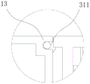
FIG. 5 is an enlarged schematic view of the cover shown in FIG. 4 at A;
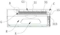
FIG. 6 is an enlarged schematic view of the dust box of FIG. 3 at B;
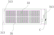
FIG. 7 is a bottom view of the cover of the dust box of FIG. 3;
FIG. 8 is a schematic cross-sectional view of a dust box in accordance with a second embodiment of the utility model;
FIG. 9 is an enlarged schematic view of the dust box of FIG. 8 at D;
FIG. 10 is a top view of the dust box shown in FIG. 8;
fig. 11 is a bottom view of the cover of the dust box of fig. 8.
Reference numerals illustrate: 100. a dust box; 10. a case body; 11. a top plate; 13. a shaft groove; 15. a second buckle; 17. a dust discharge port; 30. a cover body; 31. an upper cover; 311. a rotating shaft; 313. a first buckle; 33. a filter; 35. a pressing piece; 50. a seal; 201. a magnetic member; F. a mounting port; G. a filtering space; g1, a gas passing channel; C. an air outlet; r, a containing cavity; K. a waste inlet; J. and (5) storing glue positions.
Detailed Description
In order that the above objects, features and advantages of the utility model will be readily understood, a more particular description of the utility model will be rendered by reference to the appended drawings. In the following description, numerous specific details are set forth in order to provide a thorough understanding of the present utility model. The present utility model may be embodied in many other forms than described herein and similarly modified by those skilled in the art without departing from the spirit of the utility model, whereby the utility model is not limited to the specific embodiments disclosed below.
In the description of the present utility model, it should be understood that the terms "center", "longitudinal", "lateral", "length", "width", "thickness", "upper", "lower", "front", "rear", "left", "right", "vertical", "horizontal", "top", "bottom", "inner", "outer", "clockwise", "counterclockwise", "axial", "radial", "circumferential", etc. indicate orientations or positional relationships based on the orientations or positional relationships shown in the drawings are merely for convenience in describing the present utility model and simplifying the description, and do not indicate or imply that the device or element being referred to must have a specific orientation, be configured and operated in a specific orientation, and therefore should not be construed as limiting the present utility model.
Furthermore, the terms "first," "second," and the like, are used for descriptive purposes only and are not to be construed as indicating or implying a relative importance or implicitly indicating the number of technical features indicated. Thus, a feature defining "a first" or "a second" may explicitly or implicitly include at least one such feature. In the description of the present utility model, the meaning of "plurality" means at least two, for example, two, three, etc., unless specifically defined otherwise.
In the present utility model, unless explicitly specified and limited otherwise, the terms "mounted," "connected," "secured," and the like are to be construed broadly, and may be, for example, fixedly connected, detachably connected, or integrally formed; can be mechanically or electrically connected; either directly or indirectly, through intermediaries, or both, may be in communication with each other or in interaction with each other, unless expressly defined otherwise. The specific meaning of the above terms in the present utility model can be understood by those of ordinary skill in the art according to the specific circumstances.
In the present utility model, unless expressly stated or limited otherwise, a first feature "up" or "down" a second feature may be the first and second features in direct contact, or the first and second features in indirect contact via an intervening medium. Moreover, a first feature being "above," "over" and "on" a second feature may be a first feature being directly above or obliquely above the second feature, or simply indicating that the first feature is level higher than the second feature. The first feature being "under", "below" and "beneath" the second feature may be the first feature being directly under or obliquely below the second feature, or simply indicating that the first feature is less level than the second feature.
It will be understood that when an element is referred to as being "fixed" or "disposed" on another element, it can be directly on the other element or intervening elements may also be present. When an element is referred to as being "connected" to another element, it can be directly connected to the other element or intervening elements may also be present. The terms "vertical," "horizontal," "upper," "lower," "left," "right," and the like are used herein for illustrative purposes only and are not meant to be the only embodiment.
Referring to fig. 1 to 4, an embodiment of the present utility model provides a dust box 100, which includes a box body 10 and a cover body 30, wherein the box body 10 has a mounting opening F, and the cover body 30 covers the mounting opening F and includes an upper cover 31, a filtering member 33 and a pressing member 35. The pressing member 35 is assembled to the upper cover 31 with a filtering space G formed therebetween, and the filtering member 33 is installed in the filtering space G. The cover 30 is configured with an air passage G1 and an air outlet C communicating with the air passage G1, and the pressing member 35 can allow air flow to pass through itself and enter the filter 33, and the air flow filtered by the filter 33 is discharged through the air passage G1 and the air outlet C.
It should be understood that, to achieve its normal function, the case body 10 in the dust box 100 should be formed with a receiving chamber R and a dust inlet K communicating with the receiving chamber R, so that dust generated by sweeping the floor machine can enter through the dust inlet K and be received in the receiving chamber R. The mounting opening F is also communicated with the accommodating cavity R, so that the garbage inlet K and the air outlet C can form an inflow and outflow passage. When the dust box 100 is installed to the sweeper to work, the fan generates suction force, negative pressure is formed in the cover body 30 and the accommodating cavity R of the box body 10 through the air outlet C, the dust box 100 can suck air from the garbage inlet K, and at the moment, garbage is sucked together. The air with the garbage is blown to the pressing member 35, and under the action of the filtering member 33, the air can be filtered to enter the air passing channel G1 in the cover body 30 and finally discharged from the air outlet C, and the garbage is screened out and left in the accommodating cavity R of the box body 10.
The filter 33 may be HEPA, and the assembly between the upper cover 31 and the pressing member 35 may be performed by means of clamping, bonding, screw connection, etc., which is not limited herein. The pressing member 35 should be hollow or mesh-like in at least a part of the area thereof in order to allow the air flow to pass therethrough.
In the dust box 100, the upper cover 31 is assembled with the pressing member 35 to accommodate the filter 33 therebetween, and the three are integrally formed into the cover 30. The integrated cover 30 is no longer a simple structural component, but it also serves the functions of filtering air and guiding air flow. Overall, the dust box 100 is integrally simplified into two main parts of the box body 10 and the cover body 30, and has simple structure and connection relation, and is convenient for assembly and subsequent use and maintenance.
Further, a filtering space G between a surface of the filter 33 facing away from the pressing member 35 and the upper cover 31 is configured as an air passage G1. In this manner, the air flow can sufficiently pass through the filter member 33 to be filtered thereby and then enter the air passing passage G1, and then be discharged.
To form this gas passage G1, the surface of the filter member 33 facing away from the pressing member 35 should be spaced from at least a part of the inner surface of the upper cover 31 by a structural support structure, or the upper cover 31 may be bulged and formed with a mounting table on the peripheral side, the filter member 33 being clamped between the pressing member 35 and the mounting table so as to be spaced from the other inner surface of the upper cover 31, or the filter member 33 being in a connection relationship with the pressing member 35 so as to be spaced from the other inner surface of the upper cover 31 by the pressing member 35, or the like.
Specifically, the case 10 includes a top plate 11, and the mounting opening F is formed in the top plate 11. The top plate 11 of the box body 10 is a structural plate positioned at the top of the box body 10 in a normal working state. When the blower stops working and loses suction, part of garbage can be separated from the surface of the filter element 33 under the action of gravity and returns to the accommodating cavity R.
In addition, after the cover body 30 is covered on the box body 10, the surface of the cover body 30 is flush with the surface of the box body 10, that is, the cover body 30 is covered on the box body 10 in a jogged mode, so that the surface consistency of the dust box 100 is strong.
Referring to fig. 5, in some embodiments, a glue storage position J is formed on a surface of the pressing member 35 facing the filter member 33, and the glue storage position J is used for gluing to adhere and press the filter member 33. The glue storage position J can be a gap naturally formed between the surface of the pressing piece 35 and the filtering piece 33, or can be a groove position formed on the pressing piece 35.
On the one hand, the filter element 33 can be fastened by the compression element 35, and this fastening is enhanced by the increased adhesion of the compression force to the glue. On the other hand, the gap between the pressing piece 35 and the filtering piece 33 can be filled by glue, so that the air tightness between the pressing piece 35 and the filtering piece 33 is enhanced, and air leakage is avoided.
Further, the pressing member 35 has a mesh window shape having a plurality of windows, and the filter member 33 entirely covers the plurality of windows. The louver-like press 35 can provide sufficient support while retaining a large air flow path for the filter element 33.
Referring to fig. 6 and 7 together, in the first embodiment, a rotating shaft 311 is configured at one end of the cover 30, a shaft slot 13 with an opening is formed at a side of the mounting opening F corresponding to the rotating shaft 311, and the rotating shaft 311 is detachably accommodated in the shaft slot 13 through the opening.
When the cover body 30 is mounted, the rotating shaft 311 is assembled into the shaft groove 13, and then the cover body 30 rotates around the rotating shaft 311 and covers the mounting opening F, so that the cover body 30 is simply and accurately mounted. The other end of the cover 30 can be fastened by magnetic attraction, clamping or simply by gravity.
Further, a first buckle 313 is configured at an end of the cover 30 opposite to the rotating shaft 311, and a second buckle 15 matched with the first buckle 313 is configured at a position corresponding to the first buckle 313 at the mounting opening F.
After the cover 30 is rotated around the rotation axis 311 to be closed, the first buckle 313 and the second buckle 15 can be engaged with each other to form a stable engagement relationship, so as to prevent the cover 30 from being opened and closed at will. Specifically, the rotating shaft 311 and the first buckle 313 are respectively configured at two ends of the upper cover 31, wherein the rotating shaft 311 is located at one end far from the air outlet C.
Referring to fig. 8 to 11, in the second embodiment, the opposite ends of the cover 30 are both configured with a first buckle 313, and the corresponding positions of the mounting opening F and the first buckle 313 are both configured with a second buckle 15 that mates with the first buckle 313.
The cover 30 can be first engaged with the second buckle 15 at the mounting opening F through the first buckle 313 at one end, and the first buckle 313 at the other end and the second buckle 15 at the other end can be engaged by rotating the cover 30 with the end as the rotating shaft 311, or the first buckle 313 at both ends and the second buckle 15 can be engaged at the same time.
In some embodiments, the dust box 100 further includes a sealing member 50, where the sealing member 50 is disposed on a side of the cover 30 facing the mounting opening F, for sealing the junction of the cover 30 and the box 10. The seal 50 may alternatively be connected to the case 10 or the cover 30.
The seal 50 provides a reliable seal between the cover 30 and the case 10 to prevent air leakage. The sealing member 50 may surround the entire mounting opening F and be deformed after the cover 30 is covered on the case 10 to secure the sealing effect.
In some embodiments, a dust discharge port 17 is formed on one side of the box body 10 for controlling the opening and closing. The dust discharge port 17 is closed when the sweeper sweeps the floor and is opened when the dust box 100 is cleaned. Besides manual cleaning, the floor sweeping machine can be provided with a base station, and the base station can regularly or quantitatively suck dust in the box body 10 by opening the dust discharging port 17 to automatically clean.
In the dust box 100, the cover 30 is formed by integrating the pressing member 35, the filtering member 33 and the upper cover 31, the filtering member 33 is fixed between the pressing member 35 and the upper cover 31 in a net shape, and the filtering member 33 is further pressed and fixed by applying glue to the glue storage position J on the surface of the pressing member 35. The cover 30 is closed over the case 10 and a sealed and reliable connection is formed between the two by means of the seal 50. In operation, air flows into the box body 10 and passes through the pressing piece 35 and the filtering piece 33, the filtered air flows are discharged from the air passage G1 and the air outlet C, and garbage is left in the box body 10. The dust box 100 mainly comprises an integrated cover body 30 and a box body 10, has a simple overall structure, is easy to assemble between the cover body 30 and the box body 10, and is convenient to use and maintain.
The utility model also provides a sweeper, which comprises the dust box 100. The dust box 100 has a simple structure, and is convenient to assemble and disassemble between the box body 10 and the cover body 30, and convenient to use and maintain.
Further, the sweeper further comprises an induction component, the induction component comprises a magnetic piece 201 and a Hall sensor, the magnetic piece 201 is arranged on the cover body 30, and the Hall sensor is used for inducing the magnetic piece 201.
The magnetic member 201 may be a magnetic component such as a magnet, and the hall sensor senses the magnetic member 201 on the cover 30 to determine whether the cover 30 is in place. The Hall sensor can be arranged on a main board of the sweeper, the main board receives signals of the Hall sensor, judges based on the signals and can correspondingly send out indication signals.
When there is a sequence of matching the two ends of the cover 30, the magnetic member 201 should be disposed at the end of the rear matching, so that the obtained assembly information is more accurate.
The technical features of the above-described embodiments may be arbitrarily combined, and all possible combinations of the technical features in the above-described embodiments are not described for brevity of description, however, as long as there is no contradiction between the combinations of the technical features, they should be considered as the scope of the description.
The above examples illustrate only a few embodiments of the utility model, which are described in detail and are not to be construed as limiting the scope of the utility model. It should be noted that it will be apparent to those skilled in the art that several variations and modifications can be made without departing from the spirit of the utility model, which are all within the scope of the utility model. Accordingly, the scope of protection of the present utility model is to be determined by the appended claims.
Claims (11)
1. A dust box (100) for a sweeper, the dust box (100) comprising:
a box body (10) provided with a mounting opening (F); and
A cover body (30) which is arranged on the mounting opening (F) in a covering manner and comprises an upper cover (31), a filter element (33) and a pressing piece (35); the pressing piece (35) is assembled on the upper cover (31) and forms a filtering space (G) between the pressing piece and the upper cover, and the filtering piece (33) is installed in the filtering space (G);
the cover body (30) is configured to form an air passage (G1) and an air outlet (C) communicated with the air passage (G1), the pressing piece (35) can allow air flow to pass through the pressing piece and enter the filtering piece (33), and air filtered by the filtering piece (33) flows through the air passage (G1) and is discharged from the air outlet (C).
2. The dust box (100) according to claim 1, characterized in that the filter space (G) between the surface of the filter element (33) facing away from the press element (35) and the upper cover (31) is configured as the overair channel (G1).
3. A dust box (100) according to claim 1, characterized in that the surface of the pressing element (35) facing the filter element (33) is formed with a glue reservoir (J) for gluing to adhere and press the filter element (33).
4. The dust box (100) according to claim 1, wherein one end of the cover body (30) is provided with a rotating shaft (311), a side of the mounting opening (F) corresponding to the rotating shaft (311) is provided with a shaft groove (13) with an opening, and the rotating shaft (311) is detachably accommodated in the shaft groove (13) through the opening.
5. The dust box (100) according to claim 4, wherein a first buckle (313) is configured at one end of the cover body (30) opposite to the rotating shaft (311), and a second buckle (15) matched with the first buckle (313) is configured at a position corresponding to the first buckle (313) at the mounting opening (F).
6. The dust box (100) according to claim 1, wherein a first buckle (313) is formed at two opposite ends of the cover body (30), and a second buckle (15) matched with the first buckle (313) is formed at a position corresponding to the first buckle (313) at the mounting opening (F).
7. The dust box (100) according to claim 1, wherein the dust box (100) further comprises a sealing member (50), the sealing member (50) being provided on a side of the cover body (30) facing the mounting opening (F) for sealing a junction of the cover body (30) and the box body (10).
8. A dust box (100) according to claim 1, wherein the pressure member (35) is in the form of a mesh having a plurality of windows, the filter element (33) completely covering the plurality of windows.
9. A dust box (100) according to claim 1, wherein the box body (10) comprises a top plate (11), and the mounting opening (F) is opened on the top plate (11).
10. A sweeper, characterized in that it comprises a dust box (100) according to any one of claims 1-9.
11. The sweeper according to claim 10, further comprising an induction assembly, said induction assembly comprising a magnetic member (201) and a hall sensor, said magnetic member (201) being arranged on said cover (30), said hall sensor being adapted to induce said magnetic member (201).
Priority Applications (1)
| Application Number | Priority Date | Filing Date | Title |
|---|---|---|---|
| CN202223427601.XU CN219089152U (en) | 2022-12-20 | 2022-12-20 | Dust box and floor sweeping machine |
Applications Claiming Priority (1)
| Application Number | Priority Date | Filing Date | Title |
|---|---|---|---|
| CN202223427601.XU CN219089152U (en) | 2022-12-20 | 2022-12-20 | Dust box and floor sweeping machine |
Publications (1)
| Publication Number | Publication Date |
|---|---|
| CN219089152U true CN219089152U (en) | 2023-05-30 |
Family
ID=86454084
Family Applications (1)
| Application Number | Title | Priority Date | Filing Date |
|---|---|---|---|
| CN202223427601.XU Active CN219089152U (en) | 2022-12-20 | 2022-12-20 | Dust box and floor sweeping machine |
Country Status (1)
| Country | Link |
|---|---|
| CN (1) | CN219089152U (en) |
-
2022
- 2022-12-20 CN CN202223427601.XU patent/CN219089152U/en active Active
Similar Documents
| Publication | Publication Date | Title |
|---|---|---|
| US10639575B2 (en) | Air filter with balanced seal | |
| RU2257832C2 (en) | Dust catcher for vacuum cleaner | |
| RU2003117088A (en) | VACUUM CLEANER | |
| EP0910980A2 (en) | Low noise vacuum cleaner | |
| CN101516469B (en) | A filter assembly | |
| CN111035326A (en) | A sweeping robot emptying station and sweeping robot system | |
| EP0163678B1 (en) | Vacuum cleaner filter | |
| CN219089152U (en) | Dust box and floor sweeping machine | |
| KR100414808B1 (en) | Vacuum cleaner | |
| CN221616900U (en) | Cleaning device and dust box assembly | |
| CN218553464U (en) | Filter screen device and cleaning machine | |
| CN219846337U (en) | Dust pouring structure of dust cup | |
| CN114947658A (en) | Dust box and sweeper | |
| CN218163953U (en) | Cyclone separation device for pet hair collector dust cup | |
| CN223025970U (en) | Cleaning robot | |
| CN218738720U (en) | cleaning robot | |
| CN103908194B (en) | Bedding cleaner | |
| CN117694786B (en) | Cleaning equipment and dust box components | |
| CN219813999U (en) | Dust box, cleaning equipment and cleaning system | |
| CN223682475U (en) | Dustbin components and robot vacuum cleaner | |
| CN218738823U (en) | Dust collection assembly and cleaning robot | |
| CN214549292U (en) | Dust collecting device of sweeper | |
| CN218943257U (en) | Clean basic station | |
| CN223345596U (en) | Air purifier | |
| CN217610795U (en) | Dirt cup subassembly and cleaning device |
Legal Events
| Date | Code | Title | Description |
|---|---|---|---|
| GR01 | Patent grant | ||
| GR01 | Patent grant |