CN219092934U - Mining machinery accessory production is with conveying device - Google Patents
Mining machinery accessory production is with conveying device Download PDFInfo
- Publication number
- CN219092934U CN219092934U CN202320085323.XU CN202320085323U CN219092934U CN 219092934 U CN219092934 U CN 219092934U CN 202320085323 U CN202320085323 U CN 202320085323U CN 219092934 U CN219092934 U CN 219092934U
- Authority
- CN
- China
- Prior art keywords
- fixedly connected
- blending tank
- assembly
- mounting frame
- conveying device
- Prior art date
- Legal status (The legal status is an assumption and is not a legal conclusion. Google has not performed a legal analysis and makes no representation as to the accuracy of the status listed.)
- Active
Links
- 238000005065 mining Methods 0.000 title claims abstract description 23
- 238000004519 manufacturing process Methods 0.000 title claims abstract description 14
- 238000003756 stirring Methods 0.000 claims abstract description 34
- XLYOFNOQVPJJNP-UHFFFAOYSA-N water Substances O XLYOFNOQVPJJNP-UHFFFAOYSA-N 0.000 claims abstract description 27
- 238000004140 cleaning Methods 0.000 claims abstract description 19
- 239000007921 spray Substances 0.000 claims abstract description 19
- 239000000463 material Substances 0.000 claims abstract description 17
- 238000005507 spraying Methods 0.000 claims abstract description 16
- 238000001035 drying Methods 0.000 claims abstract description 13
- 238000010438 heat treatment Methods 0.000 claims abstract description 6
- 238000002156 mixing Methods 0.000 claims description 34
- 238000009434 installation Methods 0.000 claims description 4
- 239000007788 liquid Substances 0.000 abstract description 15
- 239000012459 cleaning agent Substances 0.000 abstract description 10
- 238000002360 preparation method Methods 0.000 abstract description 9
- 238000002347 injection Methods 0.000 abstract description 4
- 239000007924 injection Substances 0.000 abstract description 4
- 238000005485 electric heating Methods 0.000 description 8
- 238000007664 blowing Methods 0.000 description 3
- 238000005538 encapsulation Methods 0.000 description 2
- 238000012986 modification Methods 0.000 description 2
- 230000004048 modification Effects 0.000 description 2
- 238000007790 scraping Methods 0.000 description 2
- 230000005540 biological transmission Effects 0.000 description 1
- 238000005516 engineering process Methods 0.000 description 1
- 238000003754 machining Methods 0.000 description 1
- 239000000243 solution Substances 0.000 description 1
Images
Classifications
-
- Y—GENERAL TAGGING OF NEW TECHNOLOGICAL DEVELOPMENTS; GENERAL TAGGING OF CROSS-SECTIONAL TECHNOLOGIES SPANNING OVER SEVERAL SECTIONS OF THE IPC; TECHNICAL SUBJECTS COVERED BY FORMER USPC CROSS-REFERENCE ART COLLECTIONS [XRACs] AND DIGESTS
- Y02—TECHNOLOGIES OR APPLICATIONS FOR MITIGATION OR ADAPTATION AGAINST CLIMATE CHANGE
- Y02P—CLIMATE CHANGE MITIGATION TECHNOLOGIES IN THE PRODUCTION OR PROCESSING OF GOODS
- Y02P70/00—Climate change mitigation technologies in the production process for final industrial or consumer products
- Y02P70/10—Greenhouse gas [GHG] capture, material saving, heat recovery or other energy efficient measures, e.g. motor control, characterised by manufacturing processes, e.g. for rolling metal or metal working
Landscapes
- Cleaning By Liquid Or Steam (AREA)
Abstract
The utility model discloses a material conveying device for mining machinery accessory production, which relates to the technical field of mining machinery accessories and comprises a material conveying device, wherein a water spraying cleaning device is fixedly arranged at the upper end of the left side of the material conveying device, and a drying device is fixedly arranged at the right side of the water spraying cleaning device. According to the utility model, the water spray cleaning device is arranged, so that the liquid prepared by the cleaning agent can be prepared in the preparation tank, the liquid is directly discharged through the spray head, the time for single preparation and injection is saved, the power provided by the second motor drives the rotating column to rotate, the liquid in the interior can be stirred through the stirring rod to finish the preparation, finally the liquid is directly sprayed out of the spray head through the valve, the transmitted accessory is cleaned, the drying device is arranged, hot air is formed by combining the power-on heat release of the heating wire and the air blown out by the fan, and the cleaned accessory can be dried by the blown hot air.
Description
Technical Field
The utility model relates to the technical field of mining machinery accessories, in particular to a conveying device for mining machinery accessory production.
Background
The utility model provides a mechanical parts processing is with conveyer is an auxiliary device that is arranged in the mechanical parts processing to treat in the machining process to carry, and current conveyer is direct to carry away the accessory that produces, and its accessory surface still remains the spot, need wash it before the encapsulation.
In the prior art, a Chinese patent document with publication number of CN214358612U and publication date of 2021, 10 and 8 is proposed to solve the above technical problems, and the technical scheme disclosed in the patent document is as follows: the utility model provides a conveyer that mining machinery accessory production was used, includes the support base, the mounting groove has been seted up to support base upper surface, the conveyer belt has been laid to the mounting groove inside, the recess has all been seted up to mounting groove trailing flank and leading flank, the quantity that the recess was seted up to the mounting groove leading flank equals the quantity that the recess was seted up to the mounting groove leading flank, the recess internally connected who sets up to the mounting groove leading flank has the fan of blowing, the recess internally connected who sets up to the mounting groove trailing flank has the induced air fan, drain pipe below fixedly connected with scraping plate, the through-hole has evenly been seted up to scraping plate surface interval, and the material conveyer that this mining machinery accessory production was used has can clear up the stain and the greasy dirt on the conveying device surface of the mining machinery accessory, can not lead to the fact the influence to the machinery accessory of follow-up transport, improves the characteristics of mining machinery accessory in the reliability of use in the production process.
In order to solve the problems that the cleaning agent is required to be additionally mixed and then injected into the box body, and the link is not easy to be simplified, the cleaning agent is treated in a mode of independently mixing the cleaning agent and then injecting the cleaning agent into the box body in the prior art, but the condition that the cleaning agent is used up and needs to be timely mixed also occurs, and further the cleaning agent is independently injected again after being externally mixed, so that the time for cleaning mechanical accessories is increased.
Disclosure of Invention
The utility model provides a conveying device for mining machinery accessory production, which aims to solve the problems in the background technology.
In order to solve the technical problems, the utility model adopts the following technical scheme:
the utility model provides a mining machinery accessory production is with feeding device, includes feeding device, feeding device's left side upper end fixed mounting has water spray belt cleaning device, water spray belt cleaning device's right side fixed mounting has drying device.
The water spray cleaning device comprises a blending tank assembly, the blending tank assembly is arranged at the upper end of the material conveying device, a stirring assembly is rotatably arranged in the blending tank assembly, and a spraying assembly is fixedly arranged at the bottom of the blending tank assembly.
The drying device comprises a mounting frame which is fixedly connected to the upper end of the right side of the material conveying device, and an exhaust hole is formed in the bottom side of the mounting frame.
The technical scheme of the utility model is further improved as follows: the conveying device comprises a conveying belt assembly, a blanking plate is fixedly connected to the right side of the conveying belt assembly, and brackets are fixedly connected to the left side and the right side of the conveying belt assembly.
The technical scheme of the utility model is further improved as follows: the blanking plate comprises a mounting frame, a first motor is fixedly connected to one side of the mounting frame, a driving roller is fixedly connected to the rotating shaft of the first motor, and the driving roller is rotatably connected to the mounting frame.
The technical scheme of the utility model is further improved as follows: the blending tank assembly comprises a telescopic rod, one side of the telescopic rod is fixedly connected to the front side support, the other side of the telescopic rod is fixedly connected with a top cover, the outer wall of the top cover is slidably connected with a blending tank, and the top of the blending tank is provided with a feed inlet.
The technical scheme of the utility model is further improved as follows: the stirring assembly comprises a second motor, one side of the second motor is fixedly connected to the rear side support, a rotating column is fixedly connected to a rotating shaft of the second motor and located inside the blending tank, sliding grooves are formed in the periphery of the outer surface of the rotating column, sliding blocks are fixedly connected to the inner walls of the sliding grooves in a sliding mode, and stirring rods are fixedly connected to the sliding blocks.
The technical scheme of the utility model is further improved as follows: the spraying assembly comprises a water pipe, the water pipe is fixedly connected to the bottom of the blending tank, and a spray head is fixedly connected to the bottom of the water pipe.
The technical scheme of the utility model is further improved as follows: the inside fixedly connected with heating wire of installing frame, the top side of installing frame rotates and is connected with the fan, just the position of fan installation is slightly higher than the heating wire.
By adopting the technical scheme, compared with the prior art, the utility model has the following technical progress:
1. the utility model provides a material conveying device for mining machinery accessory production, wherein a water spraying cleaning device is arranged on the device, liquid prepared by cleaning agents can be prepared in a preparation tank through the preparation tank assembly, a stirring assembly and a spraying assembly, the liquid is directly discharged through a spray head, the time of single preparation and injection is saved, the power provided by a second motor drives a rotating column to rotate, the liquid in the stirring column can be stirred through a stirring rod to finish preparation, finally the stirring rod is directly sprayed out of the spray head through a valve to clean a transmitted accessory, in addition, if one stirring rod is damaged during stirring, the damaged stirring rod can be detached through sliding, and the installation and the detachment are convenient.
2. The utility model provides a material conveying device for mining machinery accessory production, which is provided with a drying device, wherein a hot air is formed by combining the power-on heat release of an electric heating wire and the air blown out by a fan through a mounting frame, an exhaust hole, an electric heating wire and the fan which are arranged on the device, so that the cleaned accessory can be dried by the blown hot air, the cleaned accessory can be directly packaged after being subjected to blanking, and the accessory does not need to be dried independently.
Drawings
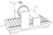
FIG. 1 is a schematic view of the overall structure of the present utility model;
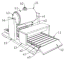
FIG. 2 is a schematic view of the water jet cleaning device shown in FIG. 1;
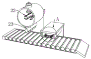
FIG. 3 is a cross-sectional view of FIG. 2 illustrating the present utility model;
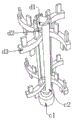
FIG. 4 is a schematic view of the stirring assembly of FIG. 3 according to the present utility model;
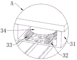
fig. 5 is an enlarged view of fig. 3 a according to the present utility model.
In the figure: 1. a material conveying device; 2. a water spray cleaning device; 3. a drying device; 11. a conveyor belt assembly; 12. a blanking plate; 13. a bracket; a1, mounting a rack; a2, a first motor; a3, a driving roller; 21. a deployment tank assembly; 22. a stirring assembly; 23. a spray assembly; b1, a blending tank; b2, a feed inlet; b3, a top cover; b4, a telescopic rod; c1, a second motor; c2, rotating the column; d1, a chute; d2, sliding blocks; d3, stirring rod; e1, a water pipe; e2, spraying heads; 31. a mounting frame; 32. an exhaust hole; 33. heating wires; 34. a blower.
Detailed Description
Referring to fig. 1-5, the present utility model provides a technical solution: the utility model provides a mining machinery accessory production is with conveyer, including conveyer 1, conveyer 1's left side upper end fixed mounting has water spray cleaning device 2, install water spray cleaning device 2 on the device, through the allotment jar subassembly 21 that sets up, stirring subassembly 22 and spray subassembly 23, make the liquid that can allocate the cleaner in allotment jar b1 modulate, directly discharge through shower nozzle e2, the time of individual allotment and injection has been saved, power drive rotation post c2 through second motor c1 provides rotates, make can stir the liquid of inside through puddler d3, accomplish the modulation, finally spout directly from shower nozzle e2 through the valve, wash the accessory of transmission, in addition this puddler d3 slidable mounting is in spout e2, if a puddler d3 damages during the stirring, can dismantle the dismantlement that will damage through the slip, be convenient for install and dismantle, cleaning device 2's right side fixed mounting has drying device 3, install drying device 3 on the device, through the installation frame 31 that sets up, exhaust vent 32, 33 and fan 34, through the heat release and the hot-air wire that blows off through the circular telegram of second motor c1 and the hot-air blowing off 34, can be directly through the hot-blast wire that can not be sealed and the hot-air blowing off after the accessory of the realization is blown out, the hot-air wire is directly need not blown out after the realization, the hot-air is dried and the material is dried and the encapsulation is directly required to be blown off.
In this embodiment, the feeding device 1 includes a conveyor belt assembly 11, a blanking plate 12 is fixedly connected to the right side of the conveyor belt assembly 11, a bracket 13 is fixedly connected to the left and right sides of the conveyor belt assembly 11, the blanking plate 12 includes a mounting frame a1, a first motor a2 is fixedly connected to one side of the mounting frame a1, a driving roller a3 is fixedly connected to a rotating shaft of the first motor a2, and the driving roller a3 is rotatably connected to the mounting frame a 1.
Preferably, the water spraying cleaning device 2 comprises a blending tank assembly 21, the blending tank assembly 21 is arranged at the upper end of the material conveying device 1, a stirring assembly 22 is rotatably arranged in the blending tank assembly 21, a spraying assembly 23 is fixedly arranged at the bottom of the blending tank assembly 21, the blending tank assembly 21 comprises a telescopic rod b4, a top cover b3 can be slidably taken out from a blending tank b1 port through telescopic action through the telescopic rod d4, the subsequent cleaning of the interior of the blending tank b1 is facilitated, one side of the telescopic rod b4 is fixedly connected to a front side bracket 13, the other side of the telescopic rod b4 is fixedly connected with a top cover b3, the outer wall of the top cover b3 is slidably connected with the blending tank b1, a feed inlet b2 is formed in the top of the blending tank b1, the stirring assembly 22 comprises a second motor c1, one side of the second motor c1 is fixedly connected to a rear side bracket 13, a rotating column c2 is fixedly connected to a rotating shaft of the second motor c1, the rotating column c2 is positioned in the blending tank b1, the periphery of the outer surface of the rotating column c2 is provided with a sliding groove d1, the inner wall of the sliding groove d1 is connected with a sliding block d2 in a sliding way, the sliding block d2 is fixedly connected with a stirring rod d3, a spraying component 23 comprises a water pipe e1, the water pipe e1 is fixedly connected to the bottom of the blending tank b1, the bottom of the water pipe e1 is fixedly connected with a spray head e2, the device is provided with a water spraying cleaning device 2, liquid blended by a cleaning agent can be modulated in the blending tank b1 through the arranged blending tank component 21, the stirring component 22 and the spraying component 23, the time for single blending and injection is saved, the rotating column c2 is driven to rotate through the power provided by a second motor c1, the internal liquid can be stirred through the stirring rod d3, the modulation is completed, finally the liquid is directly sprayed out of the spray head e2 through a valve, the transmitted fittings are cleaned, in addition, if one stirring rod d3 is damaged during stirring, the damaged stirring rod d3 can be detached through sliding, so that the stirring rod d3 is convenient to install and detach.
Further alternatively, the drying device 3 comprises a mounting frame 31, the mounting frame 31 is fixedly connected to the upper end of the right side of the material conveying device 1, an exhaust hole 32 is formed in the bottom side of the mounting frame 31, an electric heating wire 33 is fixedly connected to the inside of the mounting frame 31, a fan 34 is rotatably connected to the top side of the mounting frame 31, the mounting position of the fan 34 is slightly higher than that of the electric heating wire 33, the drying device 3 is mounted on the device, and hot air is formed by combining the electric heating wire 33 with the air blown by the fan 34 through the arranged mounting frame 31, the exhaust hole 32, the electric heating wire 33 and the heat release through the electric heating wire 33, so that the washed accessories can be dried by the blown hot air, the washed accessories can be directly packaged after being discharged conveniently, and independent drying is not needed.
The working principle of the material conveying device for mining machinery accessory production is specifically described below.
As shown in fig. 1 to 5, the liquid prepared by the cleaning agent is injected into the preparation tank b1 from the feed port b2 to be prepared, the second motor c1 is started to drive the rotary column c2 to rotate, so that the liquid in the interior is stirred by the stirring rod d3 to finish the preparation, and finally the liquid is directly sprayed out of the spray head e2 through the valve, and then the conveyed accessory can be cleaned, in addition, the stirring rod d3 is slidably arranged in the chute e2, if one stirring rod d3 is damaged during stirring, the damaged stirring rod d3 is detached through sliding, then hot air is formed by combining the power-on heat release of the electric heating wire 33 and the wind blown out by the fan 34, the blown hot air dries the water stain on the cleaned accessory, and finally the material is discharged.
The foregoing utility model has been generally described in great detail, but it will be apparent to those skilled in the art that modifications and improvements can be made thereto. Accordingly, it is intended to cover modifications or improvements within the spirit of the inventive concepts.
Claims (7)
1. The utility model provides a mining machinery accessory production is with feeding device, includes feeding device (1), its characterized in that: a water spraying cleaning device (2) is fixedly arranged at the upper end of the left side of the material conveying device (1), and a drying device (3) is fixedly arranged at the right side of the water spraying cleaning device (2);
the water spray cleaning device (2) comprises a blending tank assembly (21), the blending tank assembly (21) is arranged at the upper end of the material conveying device (1), a stirring assembly (22) is rotatably arranged in the blending tank assembly (21), and a spraying assembly (23) is fixedly arranged at the bottom of the blending tank assembly (21);
the drying device (3) comprises a mounting frame (31), the mounting frame (31) is fixedly connected to the upper right end of the material conveying device (1), and an exhaust hole (32) is formed in the bottom side of the mounting frame (31).
2. The feeder for producing mining machine parts according to claim 1, wherein: the conveying device (1) comprises a conveying belt assembly (11), a blanking plate (12) is fixedly connected to the right side of the conveying belt assembly (11), and brackets (13) are fixedly connected to the left side and the right side of the conveying belt assembly (11).
3. The feeder for producing mining machine parts according to claim 2, wherein: the blanking plate (12) comprises a mounting frame (a 1), a first motor (a 2) is fixedly connected to one side of the mounting frame (a 1), a driving roller (a 3) is fixedly connected to the rotating shaft of the first motor (a 2), and the driving roller (a 3) is rotatably connected to the mounting frame (a 1).
4. The feeder for producing mining machine parts according to claim 1, wherein: the blending tank assembly (21) comprises a telescopic rod (b 4), one side of the telescopic rod (b 4) is fixedly connected to the front side support (13), a top cover (b 3) is fixedly connected to the other side of the telescopic rod (b 4), a blending tank (b 1) is slidably connected to the outer wall of the top cover (b 3), and a feed inlet (b 2) is formed in the top of the blending tank (b 1).
5. The feeder for producing mining machine parts according to claim 1, wherein: the stirring assembly (22) comprises a second motor (c 1), one side of the second motor (c 1) is fixedly connected to the rear side support (13), a rotating column (c 2) is fixedly connected to a rotating shaft of the second motor (c 1), the rotating column (c 2) is located inside the blending tank (b 1), sliding grooves (d 1) are formed in the periphery of the outer surface of the rotating column (c 2), sliding blocks (d 2) are slidably connected to the inner walls of the sliding grooves (d 1), and stirring rods (d 3) are fixedly connected to the sliding blocks (d 2).
6. The feeder for producing mining machine parts according to claim 1, wherein: the spraying assembly (23) comprises a water pipe (e 1), the water pipe (e 1) is fixedly connected to the bottom of the blending tank (b 1), and a spray head (e 2) is fixedly connected to the bottom of the water pipe (e 1).
7. The feeder for producing mining machine parts according to claim 1, wherein: the inside fixedly connected with heating wire (33) of installing frame (31), the top side of installing frame (31) rotates and is connected with fan (34), just fan (34) installation position is slightly higher than heating wire (33).
Priority Applications (1)
| Application Number | Priority Date | Filing Date | Title |
|---|---|---|---|
| CN202320085323.XU CN219092934U (en) | 2023-01-30 | 2023-01-30 | Mining machinery accessory production is with conveying device |
Applications Claiming Priority (1)
| Application Number | Priority Date | Filing Date | Title |
|---|---|---|---|
| CN202320085323.XU CN219092934U (en) | 2023-01-30 | 2023-01-30 | Mining machinery accessory production is with conveying device |
Publications (1)
| Publication Number | Publication Date |
|---|---|
| CN219092934U true CN219092934U (en) | 2023-05-30 |
Family
ID=86462440
Family Applications (1)
| Application Number | Title | Priority Date | Filing Date |
|---|---|---|---|
| CN202320085323.XU Active CN219092934U (en) | 2023-01-30 | 2023-01-30 | Mining machinery accessory production is with conveying device |
Country Status (1)
| Country | Link |
|---|---|
| CN (1) | CN219092934U (en) |
Cited By (1)
| Publication number | Priority date | Publication date | Assignee | Title |
|---|---|---|---|---|
| CN117259310A (en) * | 2023-11-16 | 2023-12-22 | 山东优特智能科技有限公司 | Cleaning and drying equipment for rod product processing |
-
2023
- 2023-01-30 CN CN202320085323.XU patent/CN219092934U/en active Active
Cited By (2)
| Publication number | Priority date | Publication date | Assignee | Title |
|---|---|---|---|---|
| CN117259310A (en) * | 2023-11-16 | 2023-12-22 | 山东优特智能科技有限公司 | Cleaning and drying equipment for rod product processing |
| CN117259310B (en) * | 2023-11-16 | 2024-02-09 | 山东优特智能科技有限公司 | Cleaning and drying equipment for rod product processing |
Similar Documents
| Publication | Publication Date | Title |
|---|---|---|
| CN219092934U (en) | Mining machinery accessory production is with conveying device | |
| CN106109249A (en) | A kind of capsule polishing drying integral machine | |
| CN212796813U (en) | Convenient mixed automatic cleaning agent spraying equipment for car washer | |
| CN211515313U (en) | Petrochemical industry tower belt cleaning device for internals | |
| CN222659058U (en) | A spraying device for processing air conditioner shell | |
| CN209901829U (en) | Cleaning device | |
| CN210936107U (en) | Gel washing device based on gel product | |
| CN219824863U (en) | Scribing device for road construction | |
| CN214417145U (en) | Energy-efficient integrative equipment of drying that washs | |
| CN216679428U (en) | Tobacco throwing line feeder section of thick bamboo wall cleaning device | |
| CN217455933U (en) | Gantry arm car washing device | |
| CN217251063U (en) | Manganese sand filter material cleaning equipment | |
| CN114812103A (en) | Automatic cleaning and drying equipment for phosphorus copper ball processing | |
| CN206390244U (en) | A kind of washing soybean discharging drying device | |
| CN213594618U (en) | Automatic bagging device for edible mushroom production | |
| CN104872797B (en) | A kind of high-efficiency washing device of the high-volume fruit with blowning installation | |
| CN211254218U (en) | Air-blowing type cleaning device for belt conveyor | |
| CN209251724U (en) | A kind of fodder granulating machine preheating device | |
| CN216704038U (en) | Mixing device with self-cleaning function for green house decoration | |
| CN216877862U (en) | Wall-sticking-preventing spray drying device | |
| CN221537409U (en) | Surface cleaning device for repairing metal product | |
| CN214792359U (en) | High-efficient drying device is used in ground rice production | |
| CN219972903U (en) | Scribing device for highway design | |
| CN222821520U (en) | Device for spreading and drying wine lees and adding koji | |
| CN211133611U (en) | A gravity-free mixer for feed additives |
Legal Events
| Date | Code | Title | Description |
|---|---|---|---|
| GR01 | Patent grant | ||
| GR01 | Patent grant |