CN219123787U - Multi-energy complementary comprehensive energy service management equipment suitable for park - Google Patents
Multi-energy complementary comprehensive energy service management equipment suitable for park Download PDFInfo
- Publication number
- CN219123787U CN219123787U CN202223355317.6U CN202223355317U CN219123787U CN 219123787 U CN219123787 U CN 219123787U CN 202223355317 U CN202223355317 U CN 202223355317U CN 219123787 U CN219123787 U CN 219123787U
- Authority
- CN
- China
- Prior art keywords
- air inlet
- air
- cabinet body
- cabinet
- air outlet
- Prior art date
- Legal status (The legal status is an assumption and is not a legal conclusion. Google has not performed a legal analysis and makes no representation as to the accuracy of the status listed.)
- Active
Links
- 230000000295 complement effect Effects 0.000 title claims abstract description 26
- 238000000926 separation method Methods 0.000 claims abstract description 18
- 238000005192 partition Methods 0.000 claims abstract description 15
- 230000005540 biological transmission Effects 0.000 claims abstract description 10
- 230000000149 penetrating effect Effects 0.000 claims description 4
- 238000005259 measurement Methods 0.000 claims 1
- 230000017525 heat dissipation Effects 0.000 abstract description 13
- 238000010248 power generation Methods 0.000 description 11
- 238000009434 installation Methods 0.000 description 5
- 230000005611 electricity Effects 0.000 description 2
- XLYOFNOQVPJJNP-UHFFFAOYSA-N water Substances O XLYOFNOQVPJJNP-UHFFFAOYSA-N 0.000 description 2
- 230000009286 beneficial effect Effects 0.000 description 1
- 238000001816 cooling Methods 0.000 description 1
- 230000007547 defect Effects 0.000 description 1
- 238000005516 engineering process Methods 0.000 description 1
- 238000004519 manufacturing process Methods 0.000 description 1
- 238000012986 modification Methods 0.000 description 1
- 230000004048 modification Effects 0.000 description 1
- 238000005457 optimization Methods 0.000 description 1
Images


Landscapes
- Cooling Or The Like Of Electrical Apparatus (AREA)
Abstract
The utility model discloses multifunctional complementary comprehensive energy service management equipment suitable for a park, which relates to the technical field of energy control and management and comprises a comprehensive control cabinet, wherein the comprehensive control cabinet comprises a cabinet body, the cabinet body is internally divided into a plurality of separation cavities by a plurality of horizontally arranged partition boards, each separation cavity is internally provided with a mounting plate, one side of the cabinet body is provided with an air inlet assembly, the other side of the cabinet body is provided with an air outlet assembly, the cabinet body at two ends of each separation cavity is provided with an air inlet and an air outlet, the air inlet assembly and the air outlet assembly are communicated with the separation cavities through the air inlet and the air outlet, the air inlet of each separation cavity is provided with an air door plate, the air door plate is in transmission connection with a driver fixed on the cabinet body for controlling the opening and closing of the air inlet, and the front of the cabinet body is provided with a cabinet door provided with a controller which is electrically connected with the air inlet assembly and the driver. The problem that a comprehensive control cabinet of a multifunctional complementary system in the prior art cannot flexibly control a heat dissipation area is solved.
Description
Technical Field
The utility model relates to the technical field of energy control and management, in particular to a multifunctional complementary comprehensive energy service management device suitable for a park.
Background
The park comprehensive energy management and control system performs coordinated control operation on multiple energy sources such as electricity, cold and heat in the park, and the maximization of the comprehensive utilization of the electricity, the water, the heat and the cold in the whole optimization period is realized on the premise of safe and reliable operation of a power grid, stable supply of the water, the cold and the renewable energy source maximization. In the prior art, new energy development is rapid, a comprehensive energy service management system with multiple energy complementation is established in a park, which is the development trend of the present park, and the multiple energy complementation is to supply the power utilization circuit of the park by utilizing the multiple energy complementation scheduling of municipal power, photovoltaic self-power generation, solar self-power generation, wind power generation power, diesel generator and the like, so that the supply of multiple energy sources to the park circuit is realized, and the green sustainable development is realized. In a multi-energy complementary system, an integrated control cabinet is needed to coordinate and control the mobilization and supplementary supply of energy and power complementation. The existing comprehensive control cabinet needs to continuously radiate the electrified control circuit equipment, but because several supply sources of photovoltaic self-power generation, solar self-power generation, wind power generation power and diesel generators in the multi-energy complementary system circuit do not continuously work, a large amount of energy sources can be consumed to continuously radiate the partial circuit equipment when the multifunctional complementary system circuit does not work, and the multifunctional complementary system circuit is unfavorable for the green production concept.
The patent with the publication number of CN213692891U discloses an energy-saving power distribution control cabinet of an intelligent building, the comprehensive control cabinet is provided with a servo motor which can drive a transmission screw rod to rotate, the transmission screw rod which rotates can drive a linkage seat to move up and down, the movable linkage seat can drive a fan to move, the moving fan can blow air at all positions in the cabinet body to realize heat dissipation of electronic elements in the cabinet, but the cooling mode cannot meet the heat dissipation of a plurality of areas in the cabinet body under the working condition of the electronic elements, and also cannot flexibly control whether different areas are required for heat dissipation, so that the requirements in a multifunctional complementary system cannot be met.
Disclosure of Invention
Aiming at the defects in the background technology, the utility model provides a multifunctional complementary comprehensive energy service management device suitable for a park, which aims to solve the problem that a comprehensive control cabinet of a multifunctional complementary system in the prior art cannot flexibly control a heat dissipation area.
The technical scheme of the utility model is realized as follows: the utility model provides a multipotency complementary comprehensive energy service management equipment suitable for garden, includes the integrated control cabinet, the integrated control cabinet includes the cabinet body, the internal baffle that is set up by a plurality of level of cabinet separates into a plurality of and separates the chamber, all be equipped with the mounting panel in every separates the chamber, cabinet body one side is equipped with the air inlet subassembly, cabinet body opposite side is equipped with the air-out subassembly, all be equipped with air intake and air outlet on the cabinet body at every separates chamber both ends, air inlet subassembly and air-out subassembly are linked together through air intake and air outlet and separate the chamber, the air intake department of every separates the chamber is equipped with the wind door plant, the wind door plant is connected with the driver transmission of fixing on the cabinet body and is used for controlling the switching of air intake, the cabinet body openly is equipped with the cabinet door, be equipped with the controller on the cabinet door, controller and air inlet subassembly and driver electric connection.
Preferably, the air inlet assembly comprises an air inlet channel, and the air inlet channel is connected with the air inlet through a plurality of air channels.
Preferably, a fan is arranged in the air inlet duct.
Preferably, the air outlet assembly comprises an air outlet channel, and the air outlet channel is connected with the air outlet through a plurality of three-way connectors.
Preferably, the mounting plate is fixedly arranged in the separation chamber, the upper part of the mounting plate is fixedly provided with a mounting clamping rail, and the lower part of the mounting plate is provided with a plurality of through holes.
Preferably, the air door plate comprises a rectangular plate body which is arranged on the side wall of the separation cavity in a sliding mode, and the rectangular plate body is in transmission connection with the driver.
Preferably, the driver comprises an electromagnetic push rod, a fixed end of the electromagnetic push rod is fixedly connected with the side wall of the separation cavity, a telescopic part of the electromagnetic push rod is fixedly connected with the rectangular plate body, the telescopic direction of the electromagnetic push rod is consistent with the sliding direction of the rectangular plate body, the rectangular plate body can be opened and closed to the air inlet, and the electromagnetic push rod is electrically connected with the controller.
Preferably, a cable penetrating hole is formed in the back of the cabinet body.
The utility model has the beneficial effects that: by arranging a plurality of separation cavities, the electronic control elements of a plurality of electric energy supply systems in the multi-energy complementary system are independently arranged in a partition mode; the air inlet assembly and the air outlet assembly are arranged to supply air and exhaust air to the inside of the separation cavity, the installation of the electronic control element can be facilitated by arranging the mounting plate, and the air inlet can be opened and closed by arranging the air door plate in transmission connection with the driver; the controller can control the air inlet power of the air inlet assembly through the electric connection between the air inlet assembly and the controller, when heat dissipation is not required to be carried out on a certain separation cavity, the controller controls the driver to work so as to seal the air inlet of the air inlet, and meanwhile, the air inlet power of a corresponding proportion is reduced, so that the accurate control of heat dissipation efficiency and heat dissipation areas is realized, and the problem that the comprehensive control cabinet of the multi-energy complementary system in the prior art cannot flexibly control the heat dissipation areas is solved.
Drawings
In order to more clearly illustrate the embodiments of the present utility model, the drawings that are required for the description of the embodiments will be briefly described below, it being apparent that the drawings in the following description are only some embodiments of the present utility model and that other drawings may be obtained from these drawings without inventive effort for a person of ordinary skill in the art.
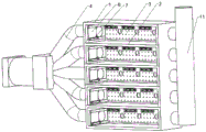
FIG. 1 is a schematic view of an external perspective structure of the present utility model;
FIG. 2 is a schematic view of the internal perspective structure of the present utility model;
fig. 3 is an enlarged schematic view of the internal structure of the present utility model.
Detailed Description
The following description of the embodiments of the present utility model will be made clearly and completely with reference to the accompanying drawings, in which it is apparent that the embodiments described are only some embodiments of the present utility model, but not all embodiments. All other embodiments, which can be made by those skilled in the art based on the embodiments of the utility model without any inventive effort, are intended to be within the scope of the utility model.
As shown in fig. 1 and 2, embodiment 1, a multifunctional complementary comprehensive energy service management device suitable for a park comprises a comprehensive control cabinet, wherein the comprehensive control cabinet comprises a cabinet body 1, a plurality of partition boards 2 horizontally arranged in the cabinet body 1 are divided into a plurality of partition cavities, each partition cavity is internally provided with a mounting plate 3, one side of the cabinet body 1 is provided with an air inlet component 4, the other side of the cabinet body 1 is provided with an air outlet component 5, the cabinet bodies at two ends of each partition cavity are respectively provided with an air inlet and an air outlet, the air inlet component 4 and the air outlet component 5 are communicated with the partition cavities through the air inlet and the air outlet, an air door plate 6 is arranged at the air inlet of each partition cavity, the air door plate 6 is in transmission connection with a driver 7 fixedly arranged on the cabinet body 1 to control the opening and closing of the air inlet, the front of the cabinet body 1 is provided with a cabinet door 14, the cabinet door 14 is provided with a controller 8, and the controller 8 is electrically connected with the air inlet component 4 and the driver 7. By arranging a plurality of separation cavities, the electronic control elements of a plurality of electric energy supply systems in the multi-energy complementary system are independently arranged in a partition mode; the air inlet assembly and the air outlet assembly are arranged to supply air and exhaust air to the inside of the separation cavity, the installation of the electronic control element can be facilitated by arranging the mounting plate, and the air inlet can be opened and closed by arranging the air door plate in transmission connection with the driver; the controller can control the air inlet power of the air inlet assembly through the electric connection between the air inlet assembly and the controller, when heat dissipation is not required to be carried out on a certain separation cavity, the controller controls the driver to work so as to seal the air inlet of the air inlet, and meanwhile, the air inlet power of a corresponding proportion is reduced, so that the accurate control of heat dissipation efficiency and heat dissipation areas is realized, and the problem that the comprehensive control cabinet of the multi-energy complementary system in the prior art cannot flexibly control the heat dissipation areas is solved.
When the novel solar energy power generation system is applied, five compartments are arranged in total, municipal power, photovoltaic self-power generation, solar self-power generation, wind power generation power and a plurality of corresponding electronic control elements of a diesel generator are all installed on a mounting plate in the compartments and are electrically connected with a controller arranged on a cabinet door, so that the controller can control on-off opening and closing of the controller.
In embodiment 2, based on embodiment 1, the air intake assembly 4 includes an air intake duct 9, and the air intake duct 9 is connected to the air intake through a plurality of air ducts 10. Wherein, a fan 15 is arranged in the air inlet duct 9.
Further, the air outlet assembly 5 comprises an air outlet channel 11, and the air outlet channel 11 is connected with the air outlet through a plurality of three-way connectors. In this embodiment, the fan is electrically connected to the controller, and when the power of the air inlet assembly needs to be controlled, the air output of the fan is controlled to change the air supply power, and meanwhile, the damper plate of the corresponding compartment is opened and closed, so that the corresponding secondary air channel cannot supply air.
As shown in fig. 3, in embodiment 3, on the basis of embodiment 2, a mounting plate 3 is fixedly arranged inside a compartment, a mounting clamping rail 12 is fixedly arranged at the upper part of the mounting plate 3, and a plurality of through holes are formed at the lower part of the mounting plate 3. The back of the cabinet body 1 is provided with a cable penetrating hole 13. The installation clamping rail is arranged, the installation of the electronic control element of the quick connection type can be facilitated, and the through holes are arranged, so that the installation of the electronic control element of the common type is facilitated. The cable penetrating holes are formed, so that the electronic control element can conveniently penetrate out of the cabinet body and be electrically connected with municipal power, photovoltaic self-power, solar self-power, wind power generation power or a diesel generator.
The driver 7 comprises an electromagnetic push rod, a fixed end of the electromagnetic push rod is fixedly connected with the side wall of the separation cavity, a telescopic part of the electromagnetic push rod is fixedly connected with the rectangular plate body, the telescopic direction of the electromagnetic push rod is consistent with the sliding direction of the rectangular plate body, the rectangular plate body can be opened and closed to the air inlet, and the electromagnetic push rod is electrically connected with the controller 8.
When the air inlet needs to be opened or closed, the controller controls the electromagnetic push rod to stretch out and draw back, so that the air inlet is opened or closed by driving the air door plate to move.
The foregoing description of the preferred embodiments of the utility model is not intended to be limiting, but rather is intended to cover all modifications, equivalents, alternatives, and improvements that fall within the spirit and scope of the utility model.
Claims (8)
1. The utility model provides a multipotency complementary comprehensive energy service management equipment suitable for garden, includes integrated control cabinet, its characterized in that: the comprehensive control cabinet comprises a cabinet body (1), wherein a plurality of partition boards (2) horizontally arranged in the cabinet body (1) are divided into a plurality of partition cavities, each partition cavity is internally provided with a mounting plate (3), one side of the cabinet body (1) is provided with an air inlet component (4), the other side of the cabinet body (1) is provided with an air outlet component (5), the cabinet bodies at two ends of each partition cavity are respectively provided with an air inlet and an air outlet, the air inlet component (4) and the air outlet component (5) are communicated with the partition cavities through the air inlet and the air outlet, an air door plate (6) is arranged at the air inlet of each partition cavity, the air door plate (6) is in transmission connection with a driver (7) fixedly arranged on the cabinet body (1) for controlling the opening and closing of the air inlet, the front of the cabinet body (1) is provided with a cabinet door (14), the cabinet door (14) is provided with a controller (8), and the controller (8) is electrically connected with the air inlet component (4) and the driver (7).
2. The multi-energy complementary integrated energy service management device for a campus of claim 1, wherein: the air inlet assembly (4) comprises an air inlet channel (9), and the air inlet channel (9) is connected with the air inlet through a plurality of air channels (10).
3. The multi-energy complementary integrated energy service management device for a campus of claim 2, wherein: a fan (15) is arranged in the air inlet duct (9).
4. The multi-energy complementary integrated energy service management device for a campus of claim 3, wherein: the air outlet assembly (5) comprises an air outlet channel (11), and the air outlet channel (11) is connected with the air outlet through a plurality of three-way connectors.
5. The multi-energy complementary integrated energy service management device for a campus of claim 4, wherein: the mounting plate (3) is fixedly arranged inside the separation cavity, the upper portion of the mounting plate (3) is fixedly provided with a mounting clamping rail (12), and the lower portion of the mounting plate (3) is provided with a plurality of through holes.
6. The multi-energy complementary integrated energy service management device for a campus of claim 5, wherein: the air door plate (6) comprises a rectangular plate body which is arranged on the side wall of the separation cavity in a sliding mode, and the rectangular plate body is in transmission connection with the driver (7).
7. The multi-energy complementary integrated energy service management device for a campus of claim 6, wherein: the driver (7) comprises an electromagnetic push rod, the fixed end of the electromagnetic push rod is fixedly connected with the side wall of the separation cavity, the telescopic part of the electrical measurement push rod is fixedly connected with the rectangular plate body, the telescopic direction of the electromagnetic push rod is consistent with the sliding direction of the rectangular plate body, the rectangular plate body can be opened and closed to the air inlet, and the electromagnetic push rod is electrically connected with the controller (8).
8. The multi-energy complementary integrated energy service management device for a campus of claim 7, wherein: the back of the cabinet body (1) is provided with a cable penetrating hole (13).
Priority Applications (1)
| Application Number | Priority Date | Filing Date | Title |
|---|---|---|---|
| CN202223355317.6U CN219123787U (en) | 2022-12-15 | 2022-12-15 | Multi-energy complementary comprehensive energy service management equipment suitable for park |
Applications Claiming Priority (1)
| Application Number | Priority Date | Filing Date | Title |
|---|---|---|---|
| CN202223355317.6U CN219123787U (en) | 2022-12-15 | 2022-12-15 | Multi-energy complementary comprehensive energy service management equipment suitable for park |
Publications (1)
| Publication Number | Publication Date |
|---|---|
| CN219123787U true CN219123787U (en) | 2023-06-02 |
Family
ID=86523599
Family Applications (1)
| Application Number | Title | Priority Date | Filing Date |
|---|---|---|---|
| CN202223355317.6U Active CN219123787U (en) | 2022-12-15 | 2022-12-15 | Multi-energy complementary comprehensive energy service management equipment suitable for park |
Country Status (1)
| Country | Link |
|---|---|
| CN (1) | CN219123787U (en) |
-
2022
- 2022-12-15 CN CN202223355317.6U patent/CN219123787U/en active Active
Similar Documents
| Publication | Publication Date | Title |
|---|---|---|
| CN213027459U (en) | Maglev flywheel energy storage power station for wind power inertia frequency modulation | |
| CN219123787U (en) | Multi-energy complementary comprehensive energy service management equipment suitable for park | |
| CN207691288U (en) | A kind of power distribution cabinet convenient to overhaul | |
| CN1381658A (en) | Photoelectric and photothermal solar equipment for building | |
| CN204089682U (en) | Adaptive wind and solar hybrid heating system | |
| CN215580921U (en) | Energy storage converter | |
| CN113131348B (en) | Outdoor intelligent alternating-current metal-armored movable switch cabinet | |
| CN206370692U (en) | The distributed energy micro-grid system of internal combustion engine alliance | |
| CN204290861U (en) | Photovoltaic generation Combined integrated machine | |
| CN223651815U (en) | A low-voltage switchgear for smart grids | |
| CN210373900U (en) | Wind-solar complementary power generation air conditioning unit | |
| CN221467200U (en) | High-low voltage complete switch cabinet convenient to maintain | |
| CN220172703U (en) | Intelligent temperature control device for low-voltage power distribution cabinet | |
| CN220383028U (en) | Container formula photovoltaic energy storage system | |
| CN209981763U (en) | Energy-saving and environment-friendly switch cabinet | |
| CN222261247U (en) | Energy storage cabinet | |
| CN223190124U (en) | Intelligent solar air conditioner ecological house | |
| CN223402379U (en) | Megawatt-level high-protection energy storage converter | |
| CN222769266U (en) | Charging Station | |
| CN224151359U (en) | Heat source device of grain dryer | |
| CN223182005U (en) | Novel integrated high-voltage frequency converter structure | |
| CN224053687U (en) | An integrated photovoltaic energy storage collaborative control cabinet | |
| CN218569667U (en) | Chinese style indoor transformer substation | |
| CN222441209U (en) | Energy storage, current conversion and voltage boosting integrated machine | |
| CN222366460U (en) | Equipment compartment heat radiation structure of energy storage cabinet |
Legal Events
| Date | Code | Title | Description |
|---|---|---|---|
| GR01 | Patent grant | ||
| GR01 | Patent grant |