CN2204663Y - Tape winding equipment for tape wound pressure vessels - Google Patents
Tape winding equipment for tape wound pressure vessels Download PDFInfo
- Publication number
- CN2204663Y CN2204663Y CN 94246893 CN94246893U CN2204663Y CN 2204663 Y CN2204663 Y CN 2204663Y CN 94246893 CN94246893 CN 94246893 CN 94246893 U CN94246893 U CN 94246893U CN 2204663 Y CN2204663 Y CN 2204663Y
- Authority
- CN
- China
- Prior art keywords
- container
- rail
- pressure vessel
- strip
- rotating disk
- Prior art date
- Legal status (The legal status is an assumption and is not a legal conclusion. Google has not performed a legal analysis and makes no representation as to the accuracy of the status listed.)
- Expired - Fee Related
Links
Images

Landscapes
- Winding, Rewinding, Material Storage Devices (AREA)
Abstract
The utility model relates to a winding apparatus for wound pressure containers. The utility model is characterized in that a container load-bearing apparatus is a supporting roller mechanism which can move on the rails and can be adjusted by lifting. The rotation of the container is transferred by an electrically-driven speed reducing mechanism positioned on and connected with the front end of the container; the supporting roller mechanism on the rear end is provided with a spacing thrust roller mechanism of the end part. Rails on both sides of the containers are provided with tape loading trolleys, a swinging rotating disk mechanism is installed on the trolley base, and the rotating disk mechanism is provided with a steel tape tensioning apparatus, a pre-bending apparatus, a variable spacing adjusting apparatus, a tension force measuring apparatus, etc. The utility model is provided with a transportation plate trailer. The utility model can ensure good attached quality of windings, and is especially suitable for windings of various big and heavy pressure vessels in large and medium types.
Description
The utility model belongs to the pressure-bearing storage technique field of gas or liquid, relates to the equipment of making pressure vessel.
The strip winding manufacturing equipment of general strip wound type pressure vessel mainly comprises the supporting whirligig of pressure vessel inner core and the take-up device of steel band winding process.Exist subject matter as follows in the world in the prior art:
1. supporting one end of winding container is blocked by the device spindle chuck, and the other end is withstood by the tail thimble, converts (see DRP, application number 262977, date of publication are 1977.9.29) by large-scale lathe usually.The not only clamping inconvenience of this clamping support pattern, and the steel band that can not carry heavy pressure vessel (can reach hundreds of ton supreme kilotons) twines;
2. container inner core outside winding steel process is only twined (end that earlier one of steel band is welded on the container inner core) in the single steel band tension of container one side, and not only strip winding efficient is low, is not suitable for big and the strip winding of long container inner core; And, easily make and drawn inner core to produce flexural deformation, or have and pulled away trend owing to only be side tension strip winding;
3. in the strip winding process tension steel band is not provided with direct device for measuring force, is difficult to accurately determine tightening force, thereby the pressure between the pressure roller of steel band is difficult to accurate adjusting, influence the strip winding quality;
4. the device that steel band pre-bending is regulated is not set, makes strip winding layer and inner core applying difficult quality guarantee, increased the difficulty of strip winding technology, in order to reach the applying quality requirement, implement hot strip winding technology, for example German Wickelofen type groove strip winding technology must adopt reason (the Please see of complicated heating (about 900 ℃) the hot winding technologe of pinch rollers, Sehierenbeck, J., Jr., U.S.Patent 2,326,176, August, 1943; Donovan, J.T., Josenhans, M., High Pressure Vessel in coal Hydrogenstion service, " Trans, Am, Soc.Mech.Engrs., 72(1950), P.357; J.P.Koenig, BASF, AG.Ludwighafen, Fabrication and Operation Experience of Wickelofen sfrip Wound Pressure Vessel, " Ammonia Plant Safety " V21.P.89-94,1979).
6. do not establish with spacing limit adjusting mechanism between the adjacent root steel band of layer, thereby when steel band twines, easily produce the superimposed phenomenon of " climbing phenomenon " steel band, and need this moment to knock adjustment with sledge hammer, can't realize automatically strip winding continuously, both influence strip winding efficient, reduced the strip winding quality again.
The purpose of this utility model is the shortcoming that will overcome prior art, a kind of tape winding devices of complete rational manufacturing pressure vessel is provided, strip winding and container inner core applying quality are good, and the side direction pulling force can be balanced when curling, and are applicable to that all kinds are particularly to the strip winding of heavy pressure vessel.
To achieve these goals, the utility model is taked following technical scheme:
The tape winding devices of this pressure vessel has following design feature: the carrying whirligig of pressure vessel inner core adopts several supporting wheel holding mechanisms that can move on rail with the support pressure vessel, the container front end is connected the location with the main shaft of electric reducer structure, mounting end limiting block wheel mechanism on the wheel holding mechanism of rear container end; On the rail of pressure vessel both sides, have respectively one can move back and forth send the band dolly, rotating disk mechanism all is housed on each dolly, rotating disk mechanism can rotate (swing) in container cross section, also can rotate in the swinging plane arbitrarily, the pre-bending device of take-up device, the steel band of steel band is being installed, the device for measuring force of tightening force when twining on rotating disk mechanism with the adjacent root steel band spacing means for adjusting limit of movement of layer strip winding and steel band.The utility model is set up some hydraulic pressure adjustable flat board holder car up and down.
Advantage of the present utility model:
1. bearing capacity is big: because the supporting wheel holding mechanism can be determined its quantity according to pressure vessel weight size, except that respectively establishing one the container front and back end, one or several supporting wheel holding mechanisms can be set still in the middle of container; And be furnished with the flat board holder car that movement is used, so this programme is specially adapted to heavy pressure vessel strip winding;
2. because strip winding carries out simultaneously along the container both sides, not only strip winding efficient improves but also to the pulling force balance of can cancelling out each other, the container inner core only bears the twisting force of strip winding;
3. because rotating disk mechanism moves two frees degree are arranged when steel band twines, promptly swing and rotate, steel band is twined by predetermined inclination (15 °~30 °), it is tangent with the axial bus of container inner core all the time to send steel band to, and before the container inner core is twined, carry out steel band pre-bending earlier and also can regulate at any time, these technical measures all can improve the applying quality of steel band around layer effectively;
4. because the adjusting device of the adjacent root steel band spacing of layer together is set, can overcome the strip winding climbing phenomenon that exists in the prior art, not need to correct with hammer, strip winding significantly improves production efficiency automatically and continuously;
5. device structure is simple especially, and is cheap for manufacturing cost.
The drawing explanation:
Fig. 1 is the utility model winding tape apparatus general structure schematic diagram;
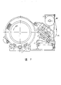
Fig. 2 is the rotating disk swing mechanism take-up device of steel band when twining on inner core, pre-bending and device for measuring force schematic diagram;
Fig. 3 is a pre-bending adjusting device structural representation;
Fig. 4 is with the adjacent root steel band of layer strip winding spacing adjusting device schematic diagram.
The contrast accompanying drawing further specifies technical scheme:
The thin inner core flat strip winding pressure vessel of various as shown in Figure 1 single or multiple lift combinations, its internal diameter varies scope is at 0.3~4m, and the length variations scope is at 2~40m, and the wall thickness change scope is at 20~300mm.The device of supporting rotation winding container inner core is made up of supporting wheel holding mechanism 3 and electric reducer structure 2, and container weight is all born by the supporting wheel holding mechanism, and forward and reverse rotation is by the main shaft transmission of reducing gear 2 during strip winding.Very long or weight is very big as container, also can be except that lay supporting wheel holding mechanism 3 in the container front and back end etc. locate to increase some supporting wheel holding mechanisms in the container stage casing, supporting wheel holding mechanism 3 move before and after can be on heavy rail and lifting adjustable, the position is anchored on the rail after determining, because the supporting wheel holding mechanism is installed on the rail, thereby overcome the restriction of ever-present receptor length and weight in the existing strip winding technical equipment fully; End limiting block wheel mechanism 4, be installed on the back end bearing wheel holding mechanism 3, and be positioned on the rail together, this limiting block wheel mechanism utilizes the rolling ring of container afterbody technology to realize that the winding container axial location with the balance strip winding axially and the side direction pulling force, it has successfully replaced large-scale tail thimble frame, its position-adjustable on rail; Electromagnetic gear clutch 5, whether 1 rotation of control container is with sending Tape movement dolly 6 to move, under the throw-out-of clutch situation, container 1 and travelling car 6 all can be operated separately, and wherein operating separately fast by the electronic reduction gearing mechanism 7 of strap brake device of travelling car realized; 1~3 can move along rail, the dull and stereotyped holder of heavy hydraulic that lifting is adjustable car 8, movement after finishing in order to the mobile installation of integral container inner core and container coiling, even thereby make hundreds of tons and even go up the heavy container of kiloton and also may not request heavy factory building and large-scale bridge type crane; Send Tape movement dolly 6 to be arranged on the rail of container both sides, a plurality of rollers are arranged on the dolly, comprise that the anti-roller that topples is installed on the rail, rotating disk mechanism 14 is housed on the chassis of dolly 6, as shown in Figure 2, the take-up device 10, pre-bending device of steel band 21 is housed on rotating disk mechanism, with layer strip winding adjacent steel interband apart from adjusting device 13, reel 20 and device for measuring force 11, the move left and right of travelling car 6 can realize by chain sprocket transmission mechanism or rack and pinion drive mechanism 9, and do not adopt common speciality screw mandrel or polished rod transmission; The take-up device 10 of flat steel band 21 is formed (wherein three are the pre-bending roller) by 7~9 diameters for the 60mm pinch rollers, and the thrust that changes between the two rows pinch rollers by rolling device can change the tightening force that steel band twines; And can amplify or hydraulic pressure force measuring machine 11 by the hinge and the lever of take-up device, measure the size of steel band pre-tensile stress at any time, and can in time regulate its size on demand; Flat steel band is equipped with the pre-bending adjusting device before being rolled up upper container, it is positioned in the front portion of steel band take-up device, as shown in Figure 3, the pre-bending adjusting device is made up of pair of straight roller 23 and a pair of pre-bending taper type roller 12 and top roller 22, the pre-bending roller pressure is adjustable, process pre-bending can guarantee the quality around the smooth applying of layer, unlikely generation warpage or arch bridge metaboly; Be installed in the hydraulic pressure on the rotating disk mechanism 14 or the guider 13 of screw mandrel transmission as shown in Figure 4, as flat steel band strip winding direction be the adjacent steel interband apart from fine adjustment mechanism, this is a kind of important and simple and effective technology that realizes the mechanization automatic coiling of tape; Rotating disk mechanism 14 is installed on the base that send band dolly 6 by hinge 19 as shown in Figure 2; As shown in Figure 1, some auxiliary equipment are arranged, the welder 15, grinder buffing device 16 of weldable steel band head, electric and microcomputer control cabinet 18 and steel coil strip shown in Figure 2 are housed at the container two ends fold and hang installing mechanism 17 etc.
Claims (8)
1, the tape winding devices of strip wound type pressure vessel, mainly form by the device and the container strip winding take-up device of supporting rotary container, the supporting arrangement that it is characterized in that container [1] is some supporting wheel holding mechanisms [3] removable on rail and that liftable is regulated, the whirligig of container [1] is electric reducer structure [2], its main shaft and container front end are located by connecting, and mounting end limiting block wheel mechanism [4] also is fixed on the rail together on the supporting wheel holding mechanism of rear container end; On the container side rail, send Tape movement dolly [6], but the take-up device [10] that is made of steel band [21] several pressure rollers that is divided into two rows dislocation arrangement is equipped with in hinged cradle housing mechanism [14] on its chassis on rotating disk mechanism.
2, the tape winding devices of strip wound type pressure vessel according to claim 1, it is characterized in that determining the quantity of adjustable support wheel holding mechanism [ 3 ] by the needs of winding container length and weight, it can be placed in the bottom of container front and back end respectively, and can settle at the container interlude, each wheel holding mechanism all is fastened on the rail at this place.
3, the tape winding devices of strip wound type pressure vessel according to claim 1, it is characterized in that sending Tape movement dolly [ 6 ] to be separately positioned on the rail of container both sides, a plurality of small-sized rollers are housed on the dolly, be installed on the rail comprising the anti-roller that topples, dolly [ 6 ] is dragged along rail by the requirement of sprocket wheel chain by the container strip winding by electric reducer structure [ 7 ], and its translational speed is regulated by reducing gear [ 7 ].
4, the tape winding devices of strip wound type pressure vessel according to claim 1, it is characterized in that on the rotating disk mechanism [ 14 ] the steel band pre-bending device being housed, it is by pair of straight roller [ 23 ] and a pair of pre-bending awl roller [ 12 ] up and down and push up and roll [ 22 ] and form the pre-bending adjustable in pressure.
5, the tape winding devices of strip wound type pressure vessel according to claim 1, it is characterized in that on rotating disk mechanism [ 14 ], being equipped with the guider [ 13 ] of hydraulic pressure or screw mandrel transmission, to regulate the spacing with the adjacent steel band of layer strip winding, the spacing adjustable range is 0~10mm.
6, the tape winding devices of strip wound type pressure vessel according to claim 1, it is characterized in that on rotating disk mechanism [ 14 ], being equipped with the device for measuring force [ 11 ] of lever or fluid pressure type, measure the suffered pulling force of steel band [ 21 ] (tightening force of strip winding) between the last lower compression roller that passes take-up device [ 10 ].
7, the tape winding devices of strip wound type pressure vessel according to claim 1, it is characterized in that rotating disk mechanism [ 14 ] is installed on the dolly [ 6 ] with hinge [ 19 ], rotating disk mechanism [ 14 ] both can also can rotate in swinging plane around hinge [ 19 ] along the container cross section swing.
8, the tape winding devices of strip wound type pressure vessel according to claim 1 is characterized in that container products after whole inner core or strip winding are finished can be placed on the adjustable hydraulic flat holder car [ 8 ] of some liftings, and Tuo Che can go up and move rail (rail).
Priority Applications (1)
| Application Number | Priority Date | Filing Date | Title |
|---|---|---|---|
| CN 94246893 CN2204663Y (en) | 1994-11-27 | 1994-11-27 | Tape winding equipment for tape wound pressure vessels |
Applications Claiming Priority (1)
| Application Number | Priority Date | Filing Date | Title |
|---|---|---|---|
| CN 94246893 CN2204663Y (en) | 1994-11-27 | 1994-11-27 | Tape winding equipment for tape wound pressure vessels |
Publications (1)
| Publication Number | Publication Date |
|---|---|
| CN2204663Y true CN2204663Y (en) | 1995-08-09 |
Family
ID=33852266
Family Applications (1)
| Application Number | Title | Priority Date | Filing Date |
|---|---|---|---|
| CN 94246893 Expired - Fee Related CN2204663Y (en) | 1994-11-27 | 1994-11-27 | Tape winding equipment for tape wound pressure vessels |
Country Status (1)
| Country | Link |
|---|---|
| CN (1) | CN2204663Y (en) |
Cited By (2)
| Publication number | Priority date | Publication date | Assignee | Title |
|---|---|---|---|---|
| CN109720906A (en) * | 2018-11-16 | 2019-05-07 | 安徽欧瑞达电器科技有限公司 | A kind of reel-off gear of copper tube |
| CN112338090A (en) * | 2020-10-20 | 2021-02-09 | 浙江巨化装备工程集团有限公司 | A new type of high-pressure container steel strip automatic winding equipment and its winding method |
-
1994
- 1994-11-27 CN CN 94246893 patent/CN2204663Y/en not_active Expired - Fee Related
Cited By (3)
| Publication number | Priority date | Publication date | Assignee | Title |
|---|---|---|---|---|
| CN109720906A (en) * | 2018-11-16 | 2019-05-07 | 安徽欧瑞达电器科技有限公司 | A kind of reel-off gear of copper tube |
| CN109720906B (en) * | 2018-11-16 | 2020-11-27 | 安徽欧瑞达电器科技有限公司 | A kind of unwinding device for copper tube |
| CN112338090A (en) * | 2020-10-20 | 2021-02-09 | 浙江巨化装备工程集团有限公司 | A new type of high-pressure container steel strip automatic winding equipment and its winding method |
Similar Documents
| Publication | Publication Date | Title |
|---|---|---|
| CN102476760A (en) | Winding equipment and winding method of solar photovoltaic solder strip tinning machine | |
| CN109607336A (en) | Automatic cable winding and unwinding device | |
| CN112139264B (en) | Conveying and transferring system for wire rod coils | |
| CN2204663Y (en) | Tape winding equipment for tape wound pressure vessels | |
| CN109205249A (en) | A kind of band transportation system | |
| CN210480444U (en) | Steel wire coil winding device | |
| CN210480445U (en) | Special take-up device equipment of electronic material for encapsulation | |
| CN116062553A (en) | A super-large packing belt horizontal winder | |
| CN112374399A (en) | Adjustable hoisting device for mechanical equipment maintenance | |
| CN112357686A (en) | Large-scale mechanical hoisting steel wire rope standby device and standby method thereof | |
| CN116281436A (en) | An adaptive and adjustable aluminum coil winding equipment | |
| CN214879131U (en) | Submerged arc welding wire winding equipment | |
| CN103267687A (en) | Carbon fiber composite mandrel winding test device | |
| CN201046472Y (en) | Pneumatic tape-steel wrapping apparatus | |
| CN209939986U (en) | Constant-tension self-adaptive thin steel strip feeding machine | |
| CN202016780U (en) | Aluminum-clad steel wire active pay-off and rewinding equipment | |
| CN218340690U (en) | Wire rewinding machine | |
| CN206286345U (en) | A kind of winding system of metal pipe material | |
| CN219418595U (en) | Strip-shaped insulating automatic cladding production line unit | |
| CN211110387U (en) | Winding device for calcium-aluminum core-spun yarn | |
| CN2071095U (en) | Horizental wire winch | |
| CN210084541U (en) | S-shaped compensation device for stainless steel strip | |
| CN218201455U (en) | Copper line rolling system of wire drawing machine | |
| CN117966156B (en) | Laser cladding device for inner hole of natural gas pipeline | |
| CN208862112U (en) | A kind of tension cache mechanism |
Legal Events
| Date | Code | Title | Description |
|---|---|---|---|
| C14 | Grant of patent or utility model | ||
| GR01 | Patent grant | ||
| C19 | Lapse of patent right due to non-payment of the annual fee | ||
| CF01 | Termination of patent right due to non-payment of annual fee |