CN2251237Y - Microphone capsule for improved sound quality - Google Patents
Microphone capsule for improved sound quality Download PDFInfo
- Publication number
- CN2251237Y CN2251237Y CN 95220353 CN95220353U CN2251237Y CN 2251237 Y CN2251237 Y CN 2251237Y CN 95220353 CN95220353 CN 95220353 CN 95220353 U CN95220353 U CN 95220353U CN 2251237 Y CN2251237 Y CN 2251237Y
- Authority
- CN
- China
- Prior art keywords
- room
- housing
- sound head
- microphone sound
- chamber
- Prior art date
- Legal status (The legal status is an assumption and is not a legal conclusion. Google has not performed a legal analysis and makes no representation as to the accuracy of the status listed.)
- Expired - Fee Related
Links
Images


Landscapes
- Audible-Bandwidth Dynamoelectric Transducers Other Than Pickups (AREA)
Abstract
The utility model provides a microphone sound head for improving tone quality includes: a housing, a chamber is recessed inwardly from the top surface of the housing, and the chamber is sequentially provided with: a yoke, a magnet, a spacer and a diaphragm having a voice coil; a protective cover covering the top of the housing to seal the chamber; wherein: the chamber is further provided with a plurality of partitions which divide the chamber into a containing space and a sound chamber positioned outside the containing space; the above-mentioned components are accommodated in the accommodation space. The utility model discloses a microphone sound head for improving tone quality created, novel structure, and have advance and good practical function.
Description
The utility model relates to microphone one microphone field, relates in particular to a kind of microphone sound head that is used to improve tonequality.
As shown in Figure 1, structure 10 for microphone sound head commonly used, it includes: a housing 12, at the end face room 14 that sets to the concave, the perisporium of housing 12 is provided with some open-works 16 and is communicated with this room 14, and be provided with in regular turn again in the room 14 of this housing 12: a yoke 18, a magnet 20, a pad 22 and a bottom surface are provided with the vibrating membrane 26 of voice coil loudspeaker voice coil 24, is located at this housing 12 tops with a lid 28 lids again, seal this room 14, form the structure of a sound head.
During use, the magnetic force linear system of this magnet 20 follows magnet 20, pad 22 to form a magnetic conduction track with yoke 18.Sound wave vibrates this vibrating membrane 26, and drives this voice coil loudspeaker voice coil 24 cutting magnetic lines after the open-work 16 of housing 12 enters housing 12 inside, converts sound wave to electric wave.
In the design of sound head commonly used, be installed in these members in the room 14 of housing 12, be to abut in the perisporium of room 14 and establish, the size system of member is big or small identical with room 14.After sound wave enters room 14, at once be subjected to these members and intercept, no suitable space, places can make sound wave bring into play the fluctuation that adds in the room 14, make effect that sound wave converts electric wave to ideal not to the utmost.
The utility model is intended to solve above-mentioned shortcoming, and promptly its main purpose is to provide a kind of microphone sound head that is used to improve tonequality, makes to have preferable effect when sound wave converts electric wave to, and makes microphone sound head have better tonequality.
For achieving the above object, the microphone sound head that is used to improve tonequality that the utility model provides, include: a housing, its end face are the room that sets to the concave, and is provided with in regular turn again in this room: a yoke, a magnet, a pad and have the vibrating membrane of voice coil loudspeaker voice coil; One over cap, it is that lid is located at this housing top, seals this room; It is characterized in that: be provided with some compartment sections in this room again, these compartment sections tie up to and are separated out a spatial accommodation in this room, and a tone chamber that is positioned at this spatial accommodation; Above-mentioned member is to be installed with in this spatial accommodation.
Be the effect that can further understand the purpose of this utility model, feature and be reached, below lift preferred embodiment of the present utility model now, and be described with reference to the accompanying drawings in after, wherein, being arranged to of accompanying drawing:
Fig. 1 is the generalized section of microphone sound head commonly used.
Fig. 2 is the exploded perspective view of the utility model preferred embodiment.
Fig. 3 is the combination section of Fig. 2.
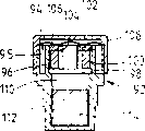
Fig. 4 is for showing the generalized section of another preferable user mode of the utility model.
At first see also Fig. 2, Fig. 3, the utility model provides is used to improve one of microphone sound head 30 preferred embodiment of tonequality, includes:
One housing 40, its end face is the room 42 that sets to the concave, and side face system is provided with most open-works 44 these rooms 42 of connection, (this preferred embodiment system is provided with the sheet compartment section that second-class spacer ring is established to be provided with some compartment sections 46 in this room 42 again, between this two compartment section, has breach), these compartment sections 46 tie up to and are separated out a spatial accommodation 48 that is positioned at these room 46 centers in this room 46, and one is positioned at the outer tone chamber 50 of this spatial accommodation 48.This housing 40 extends the socket part 52 of a hollow downwards again at root edge, and lateral circle surface is a large-diameter portion 53 on this socket part 52, then forms the less minor diameter part of an external diameter 54 below this large-diameter portion 53, multiple tool one accommodation chambers 55 in this socket part 52.One balancing weight 56 is to cement in this accommodation chamber 55, as the usefulness of counterweight.These housing 40 side faces must be pasted adjustable sound paper 58, use to coat open-work 44, filter sound wave.
One yoke 60 is the cylindrical body that without exception is the bottom surface sealing, and forms an alcove 62 in inside that this yoke 60 is in the spatial accommodation 48 that is installed with in the room 42 of this housing 40.
One magnet 65 is cylindrical, and it is to be installed with in this room 42, is contained in the alcove 62 of yoke 60.
One pad 70 is to be plate-like, and it also is installed with in this room 42, is arranged on this magnet 65.
One vibrating membrane 75, its end face system is arc surfaced; One voice coil loudspeaker voice coil 76 is to be located at this vibrating membrane 75 bottom surfaces in concentric mode.This vibrating membrane 75 also is installed with in this room 42, is arranged on this yoke 60, magnet 65 and pad 70 tops, and this voice coil loudspeaker voice coil 76 is to stretch in this spatial accommodation 48, and the boundary is between this pad 70 and this yoke 60.
One over cap 8, its periphery system extends the wall portion 82 of a predetermined length downwards, and the internal diameter system of this wall portion 82 is slightly big than the external diameter of this housing 40.This over cap 80 is that lid is located at this housing 40 tops, and above-mentioned each member 60,65,70,75 is included in this room 42, and this wall portion 82 and cover cover this housing 40 side faces.
Each member installing back of the utility model is as shown in Figure 3, to finish the structure of a microphone sound head 30.
This sound head 30 is that the socket part 52 with this housing 20 is set in default alcove in the microphone lever, and the location must be set.The large and small footpath portion 53,54 of this socket part 52 must be in response to the alcove of the different inner diameters of the microphone lever of different size and is sheathed.During use, the magnetic force linear system of this magnet 65 forms a magnetic conduction track along magnet 65, pad 70 with yoke 60, and sound wave must see through this adjustable sound paper 58, and the open-work 44 of this housing 40 certainly, enter in the tone chamber 50 of this room 42, vibrate this vibrating membrane 70, drive this voice coil loudspeaker voice coil 75 cutting magnetic lines, sound wave is converted to the effect of electric wave to carry out.
Said structure can produce following effect on reality is used:
When one, sound wave is in the external world enters housing 40, have this spacious tone chamber 50 in this room 42, make sound wave can in entering housing 40, still have preferable fluctuation, and can impel this sound head 30 to produce preferable tonequality with preferable sound wave usefulness.
Two, by the setting of this tone chamber 50, after sound wave enters housing 40, still can in room 42, possess preferable usefulness, the then promptly better lifting of the effect of this vibrating membrane 75 of sonic vibration, make this voice coil loudspeaker voice coil 76 more efficient cutting magnetic fields, improve the effect that sound wave converts electric wave to.
Three, be installed with the volume of these members in room 42 relative be little than the dust head, this equal-volume reduce phenomenon did not influence for cutting magnetic line, and can reduce manufacturing cost.
The foregoing description system shows the situation of the internal magnetization sound head that the utility model installing is commonly called as, and promptly magnet system is positioned at yoke.The utility model also must be installed the external magnetic type sound head that is commonly called as, be that magnet is positioned at outside the yoke, show this user mode with Fig. 4, the room 94 of this housing 92 still has spatial accommodation 96 and tone chamber 95, this room 94 and spatial accommodation 96 are installed with equally: a yoke 98, a magnet 100, a pad 102, have the vibrating membrane 106 of voice coil loudspeaker voice coil 104, and a cover cap is at the protecting cover 108 of these housing 102 peripheries.Wherein: the longitudinal profile system of this yoke 106 is inverted T-shaped, this magnet 100 is in the form of a ring, it is to be located on this yoke 106, and yoke 106 column positions also stretch through in the hollow part of magnet 100, and the voice coil loudspeaker voice coil 104 of this vibrating membrane 106 is to protrude out between pad 102 and yoke 98.
Effect and above-mentioned person that the preferable user mode of basis can reach are same, so do not give unnecessary details.What must remark additionally is that Fig. 2, accommodation chamber 55 its openings shown in Figure 3 get down, for installing balancing weight 56; Also as shown in Figure 4, accommodation chamber 110 is set to the concave from these room 94 diapires, be located at this socket part 112 make balancing weight 114 also cementation or card end in this accommodation chamber 110.
In sum, microphone sound head of the present utility model is innovation in like product, and has progressive, and has promoted the effect of practicality.
Claims (8)
1, a kind of microphone sound head that is used to improve tonequality includes: a housing, and its end face is the room that sets to the concave, its side face then is provided with most open-works and communicates with this room; Be provided with in regular turn again in this room: a yoke, a magnet, a pad and have the vibrating membrane of voice coil loudspeaker voice coil; One over cap, it is that lid is located at this housing top, seals this room; It is characterized in that: be provided with some compartment sections in this room again, these compartment sections lie in and are separated out a spatial accommodation in this room, and one is positioned at the outer tone chamber of this spatial accommodation; Members such as this yoke, magnet, pad system is installed with in this spatial accommodation.
2, the microphone sound head that is used to improve tonequality as claimed in claim 1 is characterized in that this spacer portion system in the form of sheets, and this spatial accommodation system establishes with the spacer portion ring of two maintenance predetermined spaces form at least, and cording is jagged between these spacer portion.
3, the microphone sound head that is used to improve tonequality as claimed in claim 1 is characterized in that this housing root edge extends a socket part again downwards.
4, the microphone sound head that is used to improve tonequality as claimed in claim 3 is characterized in that this socket part is a hollow, its inner accommodation chamber that forms; One balancing weight is to be installed with in this accommodation chamber.
5, the microphone sound head that is used to improve tonequality as claimed in claim 3, the last lateral circle surface that it is characterized in that this socket part is a large-diameter portion, under this large-diameter portion, is the less minor diameter part of an external diameter.
6, the microphone sound head that is used to improve tonequality as claimed in claim 4 is characterized in that the opening system of this accommodation chamber is positioned at the accommodation chamber bottom.
7, the microphone sound head that is used to improve tonequality as claimed in claim 4 is characterized in that this accommodation chamber system sets to the concave from the room of this housing.
8, the microphone sound head that is used to improve tonequality as claimed in claim 1, the periphery that it is characterized in that this over cap are the wall portion of extending a predetermined length downwards, and after this over cap lid was located at this housing, its system of wall portion was enclosed in this housing side face.
Priority Applications (1)
| Application Number | Priority Date | Filing Date | Title |
|---|---|---|---|
| CN 95220353 CN2251237Y (en) | 1995-08-31 | 1995-08-31 | Microphone capsule for improved sound quality |
Applications Claiming Priority (1)
| Application Number | Priority Date | Filing Date | Title |
|---|---|---|---|
| CN 95220353 CN2251237Y (en) | 1995-08-31 | 1995-08-31 | Microphone capsule for improved sound quality |
Publications (1)
| Publication Number | Publication Date |
|---|---|
| CN2251237Y true CN2251237Y (en) | 1997-04-02 |
Family
ID=33868285
Family Applications (1)
| Application Number | Title | Priority Date | Filing Date |
|---|---|---|---|
| CN 95220353 Expired - Fee Related CN2251237Y (en) | 1995-08-31 | 1995-08-31 | Microphone capsule for improved sound quality |
Country Status (1)
| Country | Link |
|---|---|
| CN (1) | CN2251237Y (en) |
Cited By (1)
| Publication number | Priority date | Publication date | Assignee | Title |
|---|---|---|---|---|
| CN101356849B (en) * | 2006-07-04 | 2011-11-23 | 日本胜利株式会社 | Microphone device |
-
1995
- 1995-08-31 CN CN 95220353 patent/CN2251237Y/en not_active Expired - Fee Related
Cited By (1)
| Publication number | Priority date | Publication date | Assignee | Title |
|---|---|---|---|---|
| CN101356849B (en) * | 2006-07-04 | 2011-11-23 | 日本胜利株式会社 | Microphone device |
Similar Documents
| Publication | Publication Date | Title |
|---|---|---|
| CA2474493C (en) | Low profile audio speaker | |
| US7916890B2 (en) | Ultra low frequency transducer and loud speaker comprising same | |
| US20070125591A1 (en) | Audio speaker with wobble free voice coil movement | |
| US7185735B2 (en) | Audio speaker with wobble free voice coil movement | |
| CZ293575B6 (en) | Acoustic device for reproduction, absorption or filtration of sound and process for producing thereof | |
| US7225895B2 (en) | Audio speaker with wobble free voice coil movement | |
| TW259832B (en) | Acoustic device using a porous structure | |
| AU2003217250A1 (en) | Low profile audio speaker | |
| NZ316550A (en) | Vibration transducers | |
| CA2198113A1 (en) | Ported Loudspeaker System and Method with Reduced Air Turbulence | |
| AU2013271505A1 (en) | Ported audio speaker enclosures | |
| CN104394492B (en) | A kind of monofilm double-tone imitates difunctional bone conduction earphone | |
| CA2188899A1 (en) | Multiple cone transducer | |
| CN2251237Y (en) | Microphone capsule for improved sound quality | |
| US20050276432A1 (en) | Horn loudspeaker | |
| US5097514A (en) | Equilateral tetrahedral speaker system | |
| JP2003522429A (en) | Loudspeaker | |
| RU2246802C2 (en) | Loudspeaker | |
| CN208285532U (en) | Electroacoustic transducer and its mould group | |
| CN206835350U (en) | Car audio system based on symmetrical balance bass box | |
| CN2673018Y (en) | Thin speaker with sprung waves | |
| CN210958787U (en) | Waterproof and fireproof ceiling horn loudspeaker | |
| CN2765421Y (en) | Structural Improvement of the Loudspeaker | |
| CN2273083Y (en) | Structurally improved sound head for microphone | |
| CN220985843U (en) | speaker |
Legal Events
| Date | Code | Title | Description |
|---|---|---|---|
| C14 | Grant of patent or utility model | ||
| GR01 | Patent grant | ||
| C19 | Lapse of patent right due to non-payment of the annual fee | ||
| CF01 | Termination of patent right due to non-payment of annual fee |