CN2384792Y - Decorative plate device - Google Patents
Decorative plate device Download PDFInfo
- Publication number
- CN2384792Y CN2384792Y CN99216482U CN99216482U CN2384792Y CN 2384792 Y CN2384792 Y CN 2384792Y CN 99216482 U CN99216482 U CN 99216482U CN 99216482 U CN99216482 U CN 99216482U CN 2384792 Y CN2384792 Y CN 2384792Y
- Authority
- CN
- China
- Prior art keywords
- post
- plate
- utility
- model
- orifice plate
- Prior art date
- Legal status (The legal status is an assumption and is not a legal conclusion. Google has not performed a legal analysis and makes no representation as to the accuracy of the status listed.)
- Expired - Fee Related
Links
- 238000003780 insertion Methods 0.000 claims description 2
- 230000037431 insertion Effects 0.000 claims description 2
- 230000002093 peripheral effect Effects 0.000 claims description 2
- 238000004519 manufacturing process Methods 0.000 abstract 1
- 229920003023 plastic Polymers 0.000 description 3
- 239000000853 adhesive Substances 0.000 description 2
- 230000001070 adhesive effect Effects 0.000 description 2
- 238000005034 decoration Methods 0.000 description 2
- 238000010586 diagram Methods 0.000 description 1
- 238000001035 drying Methods 0.000 description 1
- 230000000694 effects Effects 0.000 description 1
- 239000012467 final product Substances 0.000 description 1
- 239000003292 glue Substances 0.000 description 1
- 238000012423 maintenance Methods 0.000 description 1
- 239000000463 material Substances 0.000 description 1
- 229910052754 neon Inorganic materials 0.000 description 1
- GKAOGPIIYCISHV-UHFFFAOYSA-N neon atom Chemical compound [Ne] GKAOGPIIYCISHV-UHFFFAOYSA-N 0.000 description 1
Images


Landscapes
- Non-Portable Lighting Devices Or Systems Thereof (AREA)
Abstract
The utility model relates to a decorative plate device, which is composed of a post hole plate, a post plate, a closing plate, lamp wires, and joints. The utility model is characterized in that the surface of the post hole plate is provided with a plurality of post bodies with blind holes; the post plate is provided with a plurality of small post bodies; the small post bodies of the post plate are inserted into the blind holes of the post bodies of the post hole plate; the lamp wires are wound and hung on the post bodies of the post hole plate; both ends of the lamp wires are respectively connected with the joints the closing plate is hermetically connected with the periphery of the post hole plate and the post plate to form the decorative plate device. The utility model can be made into lamp decorative plates in various forms according to requests of users. The utility model has the advantages of easy fabrication, easy assembly, low cost, and convenient use.
Description
The utility model is to belong to the equipment that decorative advertisement is used.
At present, making used materials itself such as board, advertisement on the market can not be luminous, when the round-the-clock use of need, all need be aided with shot-light etc.The surface that has dress neon light tube, but be easy to damage, and difficulty during maintenance cost, its appearance is also weaker, does not satisfy user's requirement.
The purpose of this utility model is to propose a kind of decorative board device, can directly make the various forms lamp decoration, can round-the-clockly use, and it is effective, and the user is easy to use.
The utility model is made up of post orifice plate 1, post plate 2, closure plate 3, lamp line 4, joint 5, as shown in Figure 1, it is characterized in that: the cylinder that a plurality of band blind holes are arranged on post orifice plate 1 surface, a plurality of paxillas are arranged on the post plate 2, in the blind hole of the cylinder of the paxilla insertion post orifice plate 1 of post plate 2, lamp line 4 is on the cylinder that hangs over post orifice plate 1, and two ends connect with joint 5 respectively, the decorative board device is formed in the peripheral sealing-in of closure plate 3 and post orifice plate 1, post plate 2.Wherein, said lamp line 4 is connected to place in the flexible pipe by a plurality of pea lamps and forms, and each picks out the duplex line respectively the two ends of lamp line 4, and joint 5 places are sealed attachment.
The utility model is made up of post orifice plate 1, post plate 2, closure plate 3, lamp line 4, joint 5, the post orifice plate has a plurality of columns on 1 surface, and have small blind hole in the column, be used for inserting a plurality of posts on the post plate 2, lamp line can be wrapped on the post of post orifice plate 1, and lamp line two end lines can pick out two-wire, can use in parallel with other lamp line, the joint 5 sealed attachment form that lamp line 4 connects with other lamp line can prevent the joint electric leakage, has an accident.
The utility model is compared with prior art: because post orifice plate 1 is to peg graft with post plate 2, is made up of pea lamp in the lamp line, the inner surface of post orifice plate 1 can be coated with reflector layer, can increase brightness, there is adhesive sticker a bottom surface of closure plate 3, can be directly and post orifice plate 1 bonding being integral, can directly make various forms of lamp decoration plates according to customer requirements, daytime, effect was attractive in appearance, after the energising at night, whole structure is better, and is easy to make, and assembling easily, the user uses simply, safety, and cost is low.
Description of drawings:
Fig. 1 is the utility model general structure schematic diagram;
Fig. 2 is the front view of the utility model post orifice plate;
Fig. 3 is the vertical view of the utility model post orifice plate;
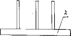
Fig. 4 is the front view of the utility model post plate;
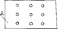
Fig. 5 is the vertical view of the utility model post plate.
Embodiment of the present utility model:
The utility model is made up of post orifice plate 1, post plate 2, closure plate 3, lamp line 4, joint 5, as shown in Figure 1; Its center pillar orifice plate 1, post plate 2, closure plate 3 are all made with transparent plastic, on its center pillar orifice plate 1 surface a plurality of columns are arranged, and blind hole is arranged in the column, coat reflector layer on the surface.The post plate has a plurality of posts on 2 surfaces, and its column diameter slightly carefully gets final product than blind hole straight line.Closure plate 3 is L types, on its base plate non-drying glue layer is arranged.The series connection of a plurality of pea lamps placed become lamp line in the thin plastic pipe, its positive and negative electrode is respectively got two wiring, and joint 5 is made of plastic, is two trapezoidal being plugged on together, can prevent electric leakage.
Pillar on the post plate 2 is inserted in the post hole of post orifice plate 1, lamp line 4 is curled on the cylinder of post orifice plate 1, and connect with post orifice plate 1 surface with the bottom surface adhesive sticker face of closure plate 3, lamp line 4 connects with joint 5, forms the decorative board device.During use, make various forms of decorative boards by customer requirements.
Claims (2)
1, a kind of decorative board device, comprise plate, lamp line, it is characterized in that: the cylinder that a plurality of band blind holes are arranged on post orifice plate (1) surface, the post plate has a plurality of paxillas on (2), in the blind hole of the post of the paxilla insertion post orifice plate (1) of post plate (2), lamp line (4) is on the cylinder that hangs over post orifice plate (1), and two ends connect with joint (5) respectively, the decorative board device is formed in the peripheral sealing-in of closure plate (3) and post orifice plate (1), post plate (2).
2, decorative board device according to claim 1 is characterized in that: said lamp line (4) is connected to place in the flexible pipe by a plurality of pea lamps and forms, and each picks out the duplex line respectively the two ends of lamp line (4), and joint (5) locates to be sealed attachment.
Priority Applications (1)
| Application Number | Priority Date | Filing Date | Title |
|---|---|---|---|
| CN99216482U CN2384792Y (en) | 1999-07-13 | 1999-07-13 | Decorative plate device |
Applications Claiming Priority (1)
| Application Number | Priority Date | Filing Date | Title |
|---|---|---|---|
| CN99216482U CN2384792Y (en) | 1999-07-13 | 1999-07-13 | Decorative plate device |
Publications (1)
| Publication Number | Publication Date |
|---|---|
| CN2384792Y true CN2384792Y (en) | 2000-06-28 |
Family
ID=34008114
Family Applications (1)
| Application Number | Title | Priority Date | Filing Date |
|---|---|---|---|
| CN99216482U Expired - Fee Related CN2384792Y (en) | 1999-07-13 | 1999-07-13 | Decorative plate device |
Country Status (1)
| Country | Link |
|---|---|
| CN (1) | CN2384792Y (en) |
-
1999
- 1999-07-13 CN CN99216482U patent/CN2384792Y/en not_active Expired - Fee Related
Similar Documents
| Publication | Publication Date | Title |
|---|---|---|
| US5396408A (en) | Detachable window decoration | |
| US20040046502A1 (en) | Environment proof treatment for electro-luminescent (EL) element(s) | |
| EP1308668B1 (en) | Structure of tube lamp | |
| CN104885143A (en) | Fixtures for transparent electronic displays | |
| US9518707B2 (en) | Strip LED | |
| CN2384792Y (en) | Decorative plate device | |
| CN201184554Y (en) | Combined luminous module of lamp | |
| CN213242531U (en) | High strength camera module chip encapsulation base | |
| CN217356784U (en) | Continuous solar LED lamp strip | |
| CN213458793U (en) | A rollable flexible transparent display | |
| CN212840875U (en) | LED lamp area with waterproof construction | |
| CN201672357U (en) | Rainbow lamp capable of displaying pixel change | |
| CN201170494Y (en) | Luminescent glass | |
| CN201273468Y (en) | LED illumination and decoration dual-purpose lamp | |
| CN2255648Y (en) | High-grade ghost sign plate | |
| CN220958350U (en) | Garden landscape lamp | |
| CN221023059U (en) | A handicraft with fantasy color effect | |
| CN2279853Y (en) | Mirror as decoration article | |
| CN214619135U (en) | LED lamp area convenient to fixed trilateral luminous | |
| CN222737619U (en) | Display rack for folding screen electronic product | |
| CN219867497U (en) | Soft lamp area is extruded to positive luminous double-colored silica gel | |
| CN2318503Y (en) | A-shaped Christmas lighting device | |
| CN215215846U (en) | 360-degree uniform light-emitting flagpole lamp | |
| CN2217251Y (en) | Neon advertising signs | |
| CN212510688U (en) | Landscape lamp |
Legal Events
| Date | Code | Title | Description |
|---|---|---|---|
| C14 | Grant of patent or utility model | ||
| GR01 | Patent grant | ||
| C19 | Lapse of patent right due to non-payment of the annual fee | ||
| CF01 | Termination of patent right due to non-payment of annual fee |