CN2437963Y - External turnover automatic emergency lamp - Google Patents

External turnover automatic emergency lamp Download PDF

Info

Publication number
CN2437963Y
CN2437963Y CN00239018U CN00239018U CN2437963Y CN 2437963 Y CN2437963 Y CN 2437963Y CN 00239018 U CN00239018 U CN 00239018U CN 00239018 U CN00239018 U CN 00239018U CN 2437963 Y CN2437963 Y CN 2437963Y
Authority
CN
China
Prior art keywords
built
automatic emergency
emergency light
transmission mechanism
control circuit
Prior art date
Legal status (The legal status is an assumption and is not a legal conclusion. Google has not performed a legal analysis and makes no representation as to the accuracy of the status listed.)
Expired - Fee Related
Application number
CN00239018U
Other languages
Chinese (zh)
Inventor
陈洪涛
吴永
Current Assignee (The listed assignees may be inaccurate. Google has not performed a legal analysis and makes no representation or warranty as to the accuracy of the list.)
Individual
Original Assignee
Individual
Priority date (The priority date is an assumption and is not a legal conclusion. Google has not performed a legal analysis and makes no representation as to the accuracy of the date listed.)
Filing date
Publication date
Application filed by Individual filed Critical Individual
Priority to CN00239018U priority Critical patent/CN2437963Y/en
Application granted granted Critical
Publication of CN2437963Y publication Critical patent/CN2437963Y/en
Anticipated expiration legal-status Critical
Expired - Fee Related legal-status Critical Current

Links

Classifications

    • YGENERAL TAGGING OF NEW TECHNOLOGICAL DEVELOPMENTS; GENERAL TAGGING OF CROSS-SECTIONAL TECHNOLOGIES SPANNING OVER SEVERAL SECTIONS OF THE IPC; TECHNICAL SUBJECTS COVERED BY FORMER USPC CROSS-REFERENCE ART COLLECTIONS [XRACs] AND DIGESTS
    • Y02TECHNOLOGIES OR APPLICATIONS FOR MITIGATION OR ADAPTATION AGAINST CLIMATE CHANGE
    • Y02BCLIMATE CHANGE MITIGATION TECHNOLOGIES RELATED TO BUILDINGS, e.g. HOUSING, HOUSE APPLIANCES OR RELATED END-USER APPLICATIONS
    • Y02B20/00Energy efficient lighting technologies, e.g. halogen lamps or gas discharge lamps
    • Y02B20/40Control techniques providing energy savings, e.g. smart controller or presence detection

Landscapes

  • Arrangement Of Elements, Cooling, Sealing, Or The Like Of Lighting Devices (AREA)

Abstract

本实用新型涉及一种自动应急灯装置,它是一种内置式翻转自动应急灯,该应急灯有控制电路、蓄电池、变压器和灯具。它还配有预置外壳,内置翻转板和传动机构;控制电路、蓄电池、变压器和传动机构均置于预置外壳内,灯具装于内置翻转板内侧,内置翻转板与传动机构的传动轮连动。本实用新型将灯具隐藏于墙内,该装置也可用于安装各类型报警器。

Figure 00239018

The utility model relates to an automatic emergency light device, which is a built-in flip automatic emergency light. The emergency light has a control circuit, a storage battery, a transformer and a lamp. It is also equipped with a preset shell with a built-in flip plate and a transmission mechanism; the control circuit, battery, transformer and transmission mechanism are all placed in the preset shell, the lamps are installed inside the built-in flip plate, and the built-in flip plate is connected with the drive wheel of the transmission mechanism. move. The utility model hides the lamp in the wall, and the device can also be used for installing various types of alarms.

Figure 00239018

Description

Built-in upset automatic emergency light
The utility model relates to a kind of automatic emergency light device, and it is a kind of built-in upset automatic emergency light.
Emergency light in the market is exposed, is promptly needing near installation bracket emergency lighting local, can be directly with lamp installation on wall; Though this kind mounting structure has solved the emergency lighting problem, but regular maintenance, administration of health to light fixture bring many troubles, particularly to some office building, large halls and guest houses and advanced hotel, restaurant and the family of interior decoration, its installation form influences the overall appearance of interior decoration.
The purpose of this utility model is to provide a kind of built-in upset automatic emergency light, and it places lamp body in the wall, has both solved health maintenance problem, does not influence indoor overall appearance again.
Above-mentioned purpose is achieved through the following technical solutions: a kind of built-in upset automatic emergency light, and it is provided with control circuit, battery, transformer, light fixture; It is characterized in that it also is provided with presets shell, built-in turning plate and transmission mechanism; Its control circuit, battery, transformer and transmission mechanism all are assemblied in and preset in the shell, and lamp installation is at built-in turning plate inboard, returning face plate and the drive of transmission mechanism is coaxial is connected.
Reducing motor, clutch, shaft coupling and driving wheel group are arranged in the described transmission mechanism; Driving wheel group is connected with reducing motor by shaft coupling, clutch.
Described driving wheel group is provided with four drives, and its first drive is connected with reducing motor, and last drive is coaxial the connection with the built-in turning plate.
Characteristics of the present utility model are: light fixture places the returning face plate inboard under off position, and this not only can protect the health maintenance and the security protection of light fixture, also can keep the whole and decoration uniformity of wall; The also replaceable one-tenth alarm of the lamp body of the built-in automatic emergency light of this kind is hidden within the walls alarm under off position, then flip out automatically if any alarm signal, goes back the record of a configurable camera with preservation accident or crime scene on its alarm.This built-in upset automatic emergency light is simple in structure, is applicable to all kinds of buildings.
Below in conjunction with accompanying drawing in detail the utility model embodiment is described in detail.
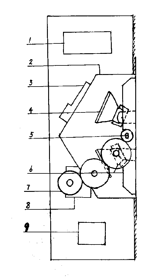
Accompanying drawing 1 built-in upset automatic emergency light structural representation.
Accompanying drawing 2 built-in upset automatic emergency light side-looking structural representations.
At first will preset shell 2 as shown in Figure 1 and do within body of wall, its battery 1, control circuit 3, reducing motor 8 and transformer 9 all place and preset in the shell 2; The lamp socket of two light fixtures 4 is installed in built-in turning plate 6 inboards, and the trip shaft 5 of its built-in turning plate 6 is coaxial the connection with last drive of driving wheel group 7.
As shown in Figure 2, first drive of driving wheel group 7 is connected with reducing motor 8 with clutch 11 by shaft coupling 10; Its last drive is coaxial the connection with built-in turning plate 6 through trip shaft 5.
After installing with control circuit 3 respectively with battery 1, light fixture 4, reducing motor 8, transformer 9 for being electrically connected; Control circuit 3 is connected with general room lighting power supply simultaneously, and makes light fixture be in the charging armed state.When the general illumination power interruptions, control circuit 3 instruction reducing motors 8 start, clutch 11 work, driving shaft coupling 10 work simultaneously makes reducing motor 8 combine with first drive of driving wheel group 7 and rotation, when the rotation of driving wheel group 7 is delivered to last drive, the rotation of its last drive with 180 ° of built-in turning plate 6 upsets, makes the light fixture 4 of built-in turning plate 6 inboards be exposed to unlatching illumination simultaneously outside the wall by trip shaft 5; Touch microswitch after 6 upsets of built-in turning plate put in place rotation is stopped, this moment, clutch continued the maintenance duty, and relied on the resistance of reducing motor 8 to stop the built-in turning plate 6 of built-in automatic emergency light to turn round, and kept lighting position.When the general illumination power up, electromagnetic clutch 11 quits work, and built-in turning plate 6 is returned to initial position under the effect of spring, and whole system is in the charging armed state.
Claims (3)

1、一种内置式翻转自动应急灯,它设置控制电路、蓄电池、变压器、灯具;其特征在于它还设置预置外壳、内置翻转板和传动机构;其控制电路、蓄电池、变压器及传动机构均装配于预置外壳内,灯具安装在内置翻转板里侧、翻转板与传动机构的传动轮同轴连接。1. A built-in flip automatic emergency light, which is equipped with a control circuit, a battery, a transformer, and a lamp; it is characterized in that it is also equipped with a preset shell, a built-in flip plate, and a transmission mechanism; its control circuit, battery, transformer, and transmission mechanism are all Assembled in the preset shell, the lamps are installed on the inner side of the built-in turning plate, and the turning plate is coaxially connected with the transmission wheel of the transmission mechanism. 2、根据权利要求1所述的内置式翻转自动应急灯,其特征在于,所述的传动机构中有减速电机、离合器、联轴器和传动轮组;传动轮组通过联轴器、离合器与减速电机连接。2. The built-in reversing automatic emergency light according to claim 1, characterized in that, the transmission mechanism includes a geared motor, a clutch, a coupling and a transmission wheel set; the transmission wheel set passes through the coupling, clutch and Geared motor connection. 3、根据权利要求1所述的内置式翻转自动应急灯,其特征在于,所述的传动轮组设置四个传动轮,其第一传动轮与减速电机连接,最后一传动轮与内置翻转板为同轴连接。3. The built-in reversing automatic emergency light according to claim 1, characterized in that the transmission wheel set is provided with four transmission wheels, the first transmission wheel is connected to the reduction motor, and the last transmission wheel is connected to the built-in reversing plate for coaxial connection.
CN00239018U 2000-06-14 2000-06-14 External turnover automatic emergency lamp Expired - Fee Related CN2437963Y (en)

Priority Applications (1)

Application Number Priority Date Filing Date Title
CN00239018U CN2437963Y (en) 2000-06-14 2000-06-14 External turnover automatic emergency lamp

Applications Claiming Priority (1)

Application Number Priority Date Filing Date Title
CN00239018U CN2437963Y (en) 2000-06-14 2000-06-14 External turnover automatic emergency lamp

Publications (1)

Publication Number Publication Date
CN2437963Y true CN2437963Y (en) 2001-07-04

Family

ID=33599953

Family Applications (1)

Application Number Title Priority Date Filing Date
CN00239018U Expired - Fee Related CN2437963Y (en) 2000-06-14 2000-06-14 External turnover automatic emergency lamp

Country Status (1)

Country Link
CN (1) CN2437963Y (en)

Cited By (3)

* Cited by examiner, † Cited by third party
Publication number Priority date Publication date Assignee Title
CN104501031A (en) * 2014-11-25 2015-04-08 常州市武进凯利达电子有限公司 Wall surface concealed type lamp
CN109084248A (en) * 2018-06-29 2018-12-25 送飞实业集团有限公司 A kind of novel concealed solar machine level ground lamp
CN111288392A (en) * 2020-03-23 2020-06-16 鹤山倍狮科技有限公司 An automatic rotary open emergency lighting

Cited By (3)

* Cited by examiner, † Cited by third party
Publication number Priority date Publication date Assignee Title
CN104501031A (en) * 2014-11-25 2015-04-08 常州市武进凯利达电子有限公司 Wall surface concealed type lamp
CN109084248A (en) * 2018-06-29 2018-12-25 送飞实业集团有限公司 A kind of novel concealed solar machine level ground lamp
CN111288392A (en) * 2020-03-23 2020-06-16 鹤山倍狮科技有限公司 An automatic rotary open emergency lighting

Similar Documents

Publication Publication Date Title
US20020172042A1 (en) Lighting fixture
CN205608475U (en) Hotel guest room management system
CN2437963Y (en) External turnover automatic emergency lamp
CN211606985U (en) Intelligent control box
CN215740651U (en) Elevator degassing unit
CN216194274U (en) Community property emergency alarm device
CN207611269U (en) An infrared remote control switch device
CN216388250U (en) Embedded auto-induction doorbell
CN105676748B (en) Wireless type socket controlling system
CN211827984U (en) Self-luminous warning assembly
CN211702768U (en) Electronic device control box convenient to heat dissipation
CN207569679U (en) A kind of wall lamp
CN220957995U (en) Hidden emergency lamp for intelligent household illumination
CN220123062U (en) Fire control broadcast speaker
CN209509727U (en) A kind of intelligent antitheft net
CN201780665U (en) Spherical crown-shaped integrated network intelligent security monitoring device
CN112672037A (en) Energy-concerving and environment-protective intelligent monitoring is with illumination electrical apparatus device
CN208737678U (en) An underground parking vacancy guidance device
CN111173366A (en) Electromagnetic clutch type manual-automatic integrated electric control handle
CN220285514U (en) A fireproof smart door lock
CN222887746U (en) Intelligent hotel RCU system based on WIFI networking
CN221825224U (en) Building corridor emergency lighting lamp
CN219995265U (en) Emergency lighting mechanism
CN213814892U (en) Safety early warning device for smart community
CN111298174A (en) Lighting disinfection system and method based on Internet of things control

Legal Events

Date Code Title Description
C14 Grant of patent or utility model
GR01 Patent grant
C19 Lapse of patent right due to non-payment of the annual fee
CF01 Termination of patent right due to non-payment of annual fee