CN2829805Y - glowing sphere - Google Patents
glowing sphere Download PDFInfo
- Publication number
- CN2829805Y CN2829805Y CN 200520109761 CN200520109761U CN2829805Y CN 2829805 Y CN2829805 Y CN 2829805Y CN 200520109761 CN200520109761 CN 200520109761 CN 200520109761 U CN200520109761 U CN 200520109761U CN 2829805 Y CN2829805 Y CN 2829805Y
- Authority
- CN
- China
- Prior art keywords
- light
- battery
- sphere
- aforementioned
- photosphere
- Prior art date
- Legal status (The legal status is an assumption and is not a legal conclusion. Google has not performed a legal analysis and makes no representation as to the accuracy of the status listed.)
- Expired - Fee Related
Links
- 239000000463 material Substances 0.000 claims description 5
- 238000009434 installation Methods 0.000 claims 5
- 241001247986 Calotropis procera Species 0.000 claims 1
- 235000019994 cava Nutrition 0.000 claims 1
- 238000007789 sealing Methods 0.000 claims 1
- 230000000694 effects Effects 0.000 description 5
- 238000000034 method Methods 0.000 description 4
- 230000007547 defect Effects 0.000 description 3
- 238000010586 diagram Methods 0.000 description 3
- 230000006698 induction Effects 0.000 description 3
- 230000008569 process Effects 0.000 description 3
- 239000004020 conductor Substances 0.000 description 2
- 238000012986 modification Methods 0.000 description 2
- 230000004048 modification Effects 0.000 description 2
- 230000003068 static effect Effects 0.000 description 2
- 230000008859 change Effects 0.000 description 1
- 238000010030 laminating Methods 0.000 description 1
- 238000004519 manufacturing process Methods 0.000 description 1
- 230000000149 penetrating effect Effects 0.000 description 1
- 230000000750 progressive effect Effects 0.000 description 1
- 230000001960 triggered effect Effects 0.000 description 1
- 238000004804 winding Methods 0.000 description 1
Images


Landscapes
- Non-Portable Lighting Devices Or Systems Thereof (AREA)
Abstract
本实用新型是有关于一种发光球体,于一充气球体内部是埋设有一以电池作为电源的供电装置,该供电装置复连接至一手动开关及震动开关,该手动开关及震动开关是连接有复数输出导线,在输出导线上设有多数发光元件;其中,输出导线及发光元件是分布在球体上,藉由控制手动开关,可直接点亮或关闭发光元件,或切换于震动感应模式,在震动感测模式下,若球体承受拍击或震动时,震动开关将自行导通而令前述电池驱动点亮该些发光元件,反之于球体静止时可自动截止而关闭发光元件。
The utility model relates to a luminous sphere. A power supply device using a battery as a power source is buried inside an inflatable sphere. The power supply device is further connected to a manual switch and a vibration switch. The manual switch and the vibration switch are connected to a plurality of output wires, and a plurality of light-emitting elements are arranged on the output wires. The output wires and the light-emitting elements are distributed on the sphere. By controlling the manual switch, the light-emitting elements can be directly turned on or off, or switched to a vibration sensing mode. In the vibration sensing mode, if the sphere is hit or vibrated, the vibration switch will automatically turn on and the battery will drive the light-emitting elements to light up. Conversely, when the sphere is stationary, the vibration switch will automatically turn on and turn off the light-emitting elements.
Description
技术领域technical field
本实用新型涉及一种发光球体,特别是涉及一种于球体上设置复数发光元件,可经由手动控制或于球体受到拍击或震动时便可自行点亮发光的球体。The utility model relates to a luminous sphere, in particular to a sphere which is provided with a plurality of luminous elements, which can be manually controlled or automatically illuminated when the sphere is slapped or shaken.
背景技术Background technique
就各种态样的运动项目来说,球类运动可说是一般人最普遍接触也是最受欢迎的体育活动,其涵盖项目极为广泛,例如篮球、足球、排球、橄榄球等,而以目前各式活动所使用到的球体的设计方向来看,因具有一定的规格限制,可以改变的几乎是仅止于球体材料及表面花纹的变化。As far as various sports items are concerned, ball games can be said to be the most common and popular sports activities for ordinary people. It covers a wide range of items, such as basketball, football, volleyball, rugby, etc. From the perspective of the design direction of the spheres used in the event, due to certain specification restrictions, what can be changed is almost limited to the change of the sphere material and surface pattern.
该些球类运动除见于正式比赛中,在更多时候是普遍成为一种三五好友间的单纯娱乐活动,但球体本身的单调造型设计,仅能为打球带来普通的娱乐效果,因此,若是得以对球体有更进一步的新颖设计,势必更能在运动过程中提供一定程度的加分作用。These ball games are not only seen in formal competitions, but more often they are pure entertainment activities between friends. However, the monotonous design of the ball itself can only bring ordinary entertainment effects to playing. Therefore, If there is a further novel design for the sphere, it is bound to provide a certain degree of extra points during the movement.
由此可见,上述现有的球体在结构与使用上,显然仍存在有不便与缺陷,而亟待加以进一步改进。为了解决球体存在的问题,相关厂商莫不费尽心思来谋求解决之道,但长久以来一直未见适用的设计被发展完成,而一般产品又没有适切的结构能够解决上述问题,此显然是相关业者急欲解决的问题。因此如何能创设一种新型结构的球体,便成了当前业界极需改进的目标。This shows that above-mentioned existing sphere obviously still has inconvenience and defect in structure and use, and urgently needs to be further improved. In order to solve the problems of the sphere, the relevant manufacturers have tried their best to find a solution, but no suitable design has been developed for a long time, and the general products do not have a suitable structure to solve the above problems. This is obviously related. The problem that the industry is eager to solve. Therefore, how to create a sphere with a new structure has become a goal that the current industry needs to improve.
有鉴于上述现有的球体存在的缺陷,本设计人基于从事此类产品设计制造多年丰富的实务经验及专业知识,并配合学理的运用,积极加以研究创新,以期创设一种新型结构的发光球体,能够改进一般现有的球体,使其更具有实用性。经过不断的研究、设计,并经反复试作样品及改进后,终于创设出确具实用价值的本实用新型。In view of the defects of the existing spheres mentioned above, based on the rich practical experience and professional knowledge engaged in the design and manufacture of such products for many years, and the application of academic theories, the designer actively researched and innovated, in order to create a new structure of luminous spheres , can improve the general existing sphere to make it more practical. Through continuous research, design, and after repeated trial samples and improvements, the utility model with practical value is finally created.
发明内容Contents of the invention
有鉴于目前球体其单调设计,本实用新型的目的在于,克服现有的球体存在的缺陷,而提供一种新型结构的发光球体,所要解决的技术问题是使其允许使用者直接控制而点亮/关闭设在球上的发光元件,或在球体受到拍击或受到震动时,令发光元件自行启动点亮,以增加运动过程中的趣味性,从而更加适于实用。In view of the monotonous design of the current sphere, the purpose of this utility model is to overcome the defects of the existing sphere and provide a luminous sphere with a new structure. The technical problem to be solved is to allow the user to directly control and light up /Turn off the luminous element arranged on the ball, or when the sphere is struck or shaken, the luminous element is automatically activated to light up, so as to increase the interest in the exercise process and thus be more suitable for practical use.
本实用新型的目的及解决其技术问题是采用以下的技术方案来实现的。依据本实用新型提出的一种发光球体,其包括有:一充气球体,是藉由多层材质叠积而成并形成有一埋设孔;一供电装置,是通过该埋设孔而设置于该球体内部;一开关装置,是连接至前述供电装置,可允许使用者手动设定而加以导通或关闭,或根据有无震动而可自行导通或关闭;复数输出导线,是连接至前述开关装置及复数发光元件,该些发光元件是分布于球体上并自前述供电装置获得电力而点亮。The purpose of this utility model and the solution to its technical problems are achieved by adopting the following technical solutions. A luminous sphere proposed according to the utility model includes: an inflatable sphere formed by laminating multiple layers of materials and forming a buried hole; a power supply device is arranged inside the sphere through the buried hole ; A switch device is connected to the aforementioned power supply device, which allows the user to manually set it to be turned on or off, or can be turned on or off automatically according to whether there is vibration; a plurality of output wires are connected to the aforementioned switch device and A plurality of light-emitting elements, these light-emitting elements are distributed on the sphere and are powered by the aforementioned power supply device to light up.
本实用新型的目的及解决其技术问题还可采用以下技术措施来进一步实现。The purpose of this utility model and the solution to its technical problems can also be further realized by adopting the following technical measures.
前述的发光球体,其中所述的开关装置包括一手动开关及一震动开关。The aforementioned luminous sphere, wherein the switch device includes a manual switch and a vibration switch.
前述的发光球体,其中所述的球体内是形成一容置前述供电装置及震动开关的橡胶套筒。The aforementioned luminous sphere, wherein a rubber sleeve is formed inside the sphere to accommodate the aforementioned power supply device and the vibration switch.
前述的发光球体,其中所述的供电装置包括:一电池筒,于封闭的内部底面设有第一导电片;一电池,是装设于前述电池筒内部,其一端与该第一导电片构成电气接触,另端是朝向电池筒的开口外部;一电池盖,其前段形成一顶块,后段形成一中空筒体具有一末端开口,该中空筒体内部顶面复连接有一导电弹簧。The above-mentioned luminous sphere, wherein the power supply device includes: a battery cylinder, which is provided with a first conductive sheet on the closed inner bottom surface; a battery, which is installed inside the aforementioned battery cylinder, and one end thereof forms Electrical contact, the other end is facing the outside of the opening of the battery cylinder; a battery cover, the front section forms a top block, and the rear section forms a hollow cylinder with an end opening, and a conductive spring is connected to the top surface of the hollow cylinder.
前述的发光球体,其中所述的电池筒在开口的内侧壁上是形成一圈挡止缘,在该挡止缘上形成两相对的导引槽,在挡止缘邻近该导引槽旁是自挡止缘的内缘处形成两定位缺口,两定位缺口上分别设有第一/第二导电接点;该于电池盖而外表面位于前述顶块后方是形一与导电弹簧电连接的导电卡块,该顶块上是形成一道凹陷的狭缝。The aforementioned luminous sphere, wherein said battery cylinder forms a ring of stop edges on the inner side wall of the opening, two opposite guide grooves are formed on the stop edges, and next to the stop edges adjacent to the guide grooves are Two positioning notches are formed on the inner edge of the self-stopping edge, and the first/second conductive contacts are respectively arranged on the two positioning notches; the outer surface of the battery cover is located behind the aforementioned top block and is a conductive spring that is electrically connected to the conductive spring. As for the clamping block, a concave slit is formed on the top block.
前述的发光球体,其中所述的震动开关是设于电池筒底部。The aforementioned luminous sphere, wherein the vibration switch is arranged at the bottom of the battery can.
前述的发光球体,其中所述的球体具有一中胎层及一外皮层,前述复数输出导线及复数发光元件是设于中胎层表面,复以外皮层包覆。The aforementioned luminous sphere, wherein said sphere has a middle tire layer and an outer skin layer, the aforementioned plurality of output wires and plurality of light emitting elements are arranged on the surface of the middle tire layer and covered by the outer skin layer.
前述的发光球体,其中所述的外皮层于对应发光元件处是形成有透光孔。In the aforementioned luminous sphere, the outer skin layer is formed with light-transmitting holes at corresponding luminescent elements.
前述开关装置可利用一手动开关结合一震动开关组成,可由使用者直接控制发光元件的点亮/关闭,或切换至震动感应模式,于球体受到拍打或震动时令震动开关自行导通,使电池的电力传递至输出导线以点亮发光元件;反之,若是回复至静止状态,震动开关恢复为关闭状态;而前述供电装置是允许使用者在电池电力耗尽后可自行更换新品。The aforementioned switch device can be composed of a manual switch combined with a vibration switch, which can be directly controlled by the user to turn on/off the light-emitting element, or switch to the vibration induction mode, and the vibration switch will be automatically turned on when the ball is slapped or vibrated, so that the power of the battery The power is transmitted to the output wire to light up the light-emitting element; otherwise, if it returns to a static state, the vibration switch returns to the off state; and the aforementioned power supply device allows the user to replace the new product by himself after the battery power is exhausted.
经由上述可知,本实用新型是有关于一种发光球体,于一充气球体内部是埋设有一以电池作为电源的供电装置,该供电装置复连接至一手动开关及震动开关,该手动开关及震动开关是连接有复数输出导线,在输出导线上设有多数发光元件;其中,输出导线及发光元件是分布在球体上,藉由控制手动开关,可直接点亮或关闭发光元件,或切换于震动感应模式,在震动感测模式下,若球体承受拍击或震动时,震动开关将自行导通而令前述电池驱动点亮该些发光元件,反之于球体静止时可自动截止而关闭发光元件。It can be seen from the above that the utility model relates to a luminous sphere. A power supply device using a battery as a power source is buried inside an inflatable sphere. The power supply device is connected to a manual switch and a vibration switch. The manual switch and the vibration switch It is connected with a plurality of output wires, and there are many light-emitting elements on the output wires; among them, the output wires and light-emitting elements are distributed on the sphere, and by controlling the manual switch, the light-emitting elements can be directly turned on or off, or switched to vibration induction. In the vibration sensing mode, if the ball is struck or shaken, the vibration switch will be automatically turned on to make the aforementioned battery drive light up the light-emitting elements, otherwise it will automatically turn off and turn off the light-emitting elements when the ball is stationary.
综上所述,本实用新型特殊结构的发光球体,允许使用者直接控制而点亮/关闭设在球上的发光元件,或在球体受到拍击或受到震动时,令发光元件自行启动点亮,以增加运动过程中的趣味性。其具有上述诸多的优点及实用价值,并在同类产品中未见有类似的结构设计公开发表或使用而确属创新,其不论在产品结构或功能上皆有较大的改进,在技术上有较大的进步,并产生了好用及实用的效果,且较现有的球体具有增进的多项功效,从而更加适于实用,而具有产业的广泛利用价值,诚为一新颖、进步、实用的新设计。To sum up, the luminous sphere with a special structure of the utility model allows the user to directly control and turn on/off the luminous element on the sphere, or make the luminous element automatically start to light up when the sphere is slapped or shaken. , to increase the interest in the exercise process. It has the above-mentioned many advantages and practical value, and there is no similar structural design publicly published or used in similar products, so it is indeed innovative. It has great improvements in both product structure and function, and is technologically advanced. It has made great progress, and produced easy-to-use and practical effects, and has improved multiple functions compared with the existing spheres, so it is more suitable for practical use, and has wide application value in the industry. It is a novel, progressive and practical product. new design.
上述说明仅是本实用新型技术方案的概述,为了能够更清楚了解本实用新型的技术手段,而可依照说明书的内容予以实施,并且为了让本实用新型的上述和其他目的、特征和优点能够更明显易懂,以下特举较佳实施例,并配合附图,详细说明如下。The above description is only an overview of the technical solutions of the present utility model. In order to better understand the technical means of the present utility model, it can be implemented according to the contents of the description, and in order to make the above-mentioned and other purposes, features and advantages of the present utility model better It is obvious and easy to understand. The preferred embodiments are specifically cited below, together with the accompanying drawings, and detailed descriptions are as follows.
附图说明Description of drawings
图1是本实用新型供电装置的立体分解图。Fig. 1 is a three-dimensional exploded view of the power supply device of the present invention.
图2是本实用新型供电装置的组合剖面图。Fig. 2 is a combined sectional view of the power supply device of the present invention.
图3是本实用新型球体中胎层的立体图。Fig. 3 is a perspective view of the tire layer in the sphere of the present invention.
图4是本实用新型手动控制模式的电路示意图。Fig. 4 is a schematic circuit diagram of the manual control mode of the utility model.
图5是本实用新型震动感测模式的电路示意图。FIG. 5 is a schematic circuit diagram of the vibration sensing mode of the present invention.
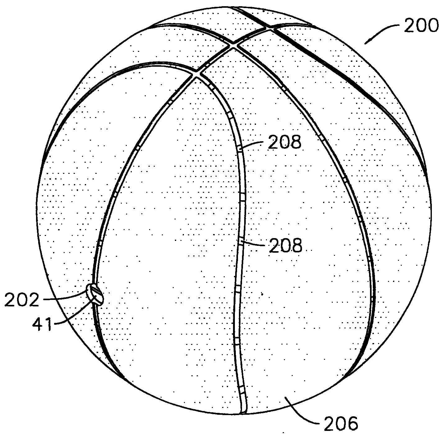
图6是本实用新型震动发光球体的立体图。Fig. 6 is a perspective view of the vibrating luminous sphere of the present invention.
100:供电装置 10:橡胶套筒100: Power supply device 10: Rubber sleeve
20:电池筒 21:第一导电片20: Battery cartridge 21: The first conductive sheet
22:24:导线 23:第二导电片22:24: Conductor 23: Second conductive sheet
25:导引槽 26:定位缺口25: Guide groove 26: Positioning gap
27:第一导电接点 28:第二导电接点27: The first conductive contact 28: The second conductive contact
30:电池 40:电池盖30: battery 40: battery cover
41:顶块 42:狭缝41: top block 42: slit
43:开口 44:电池导电片43: Opening 44: Battery conductive sheet
45:导电弹簧 46:导电卡块45: Conductive spring 46: Conductive block
50:震动开关 60:输出导线50: Vibration switch 60: Output wire
62:发光元件62: Light emitting element
200:球体 202:埋设孔200: sphere 202: buried hole
204:中胎层 206:外皮层204: middle tire layer 206: outer cortex
208:透光孔208: light hole
具体实施方式Detailed ways
为更进一步阐述本实用新型为达成预定发明目的所采取的技术手段及功效,以下结合附图及较佳实施例,对依据本实用新型提出的发光球体其具体实施方式、结构、特征及其功效,详细说明如后。In order to further explain the technical means and effects of the utility model to achieve the intended purpose of the invention, the specific implementation, structure, characteristics and efficacy of the luminous sphere proposed according to the utility model will be described below in conjunction with the accompanying drawings and preferred embodiments. , as detailed below.
本实用新型是于一球体内装设一供电装置,该供电装置可通过复数导线连接设在球面的多个发光元件,令使用者手动控制发光元件的点亮与否或于球体受到拍打或震动式可触发一震动开关而使供电装置的电力传输至该些发光元件加以点亮;反之在球体静止时,震动开关即转为关闭状态。有关本实用新型的具体架构,将配合所附图式详加说明于后。The utility model is to install a power supply device in a sphere. The power supply device can connect a plurality of light-emitting elements on the spherical surface through a plurality of wires, so that the user can manually control whether the light-emitting elements are lit or the sphere is beaten or vibrated. A vibration switch can be triggered to transmit the power of the power supply device to the light-emitting elements for lighting; otherwise, when the sphere is still, the vibration switch is turned off. The specific framework of the present utility model will be described in detail in conjunction with the accompanying drawings.
一般而言,球体是以多层不同材质积叠形成,由内而外的顺序可区分为内胎、中胎及外皮,而在内胎表面上会形成一缠纱层介于内胎及中胎之间,本实用新型适用的球体形状不拘,只要是充气式球类即可。Generally speaking, the sphere is formed by stacking multiple layers of different materials. From the inside to the outside, the order can be divided into inner tube, middle tube and outer skin, and a layer of winding yarn will be formed on the surface of the inner tube between the inner tube and the middle tube. , The shape of the sphere applicable to the utility model is not restricted, as long as it is an inflatable ball.
请参阅图1、图2所示,本实用新型在球体200上是先形成一贯穿的埋设孔202,并于球体200内形成有一橡胶套筒10,该橡胶套筒10可供埋设一供电装置100,橡胶套筒10是于一圆柱筒体的顶端开口边缘延伸一结合片而构成,橡胶套筒10可于制作球体内胎时便一体成型,以其结合片与内胎完全紧密贴合,而其圆柱筒体即向内延伸进入球体,该圆柱筒体的底部是完全密闭以防止漏气。Please refer to Fig. 1 and Fig. 2, the utility model first forms a penetrating embedding
前述位于橡胶套筒10内的供电装置100包括有:The aforementioned
一电池筒20,于内部底面设有第一导电片21,该电池筒20于开口的内部侧壁上复形成一圈挡止缘,在该挡止缘上形成两相对的导引槽25将该挡止缘贯穿而区隔为两半圆状,在挡止缘邻近该导引槽25处是自内缘处形成两定位缺口26,该定位缺口26非完全贯穿该挡止缘,于两定位缺口26的侧壁上是形成第一、第二导电接点27、28;A battery can 20 is provided with a first
一电池30,是装设于前述电池筒20内部,电池30一端与该第一导电片21构成接触,另端是朝向电池筒20的开口外部;A
一电池盖40,是为一圆柱体形状,前段形成一圆径较大的顶块41,顶块41当中是形成一道凹陷的狭缝42,而圆柱体另端具有一开口43,该开口43是朝顶块41方向延伸令圆柱体后段形成一中空筒体,于中空筒体内部顶面是连接有一导电弹簧45,于电池盖40的外表面位于前述顶块41后方是形成一导电卡块46,该导电卡块46是与前述导电弹簧45形成电连接,两者可通过设于圆柱体内部的导电材质相互连接,或通过一贴附在圆柱体表面的导电片,以该导电片连接导电卡块46与该导电弹簧45。A
在组装前述供电装置时,该电池筒20是先装设于橡胶套筒10内,再将电池30置于电池筒20内,此时电池30的一极可与第一导电片21构成电气接触,再将电池盖40装设在电池筒20内部,电池盖40后段中空部可套设固定住电池30且导电弹簧45可抵止于电池30的另一极。When assembling the aforementioned power supply device, the
于前述电池筒20的外底面是设有一震动开关50。震动开关50是连接至前述第一导电接点27及第二导电接点28(如图3所示),又前述第一导电接点27及第二导电接点28是可经由输出导线60连接复数发光元件62。A vibrating
请参阅图3所示,输出导线60是分布于球体200的中胎层204表面上,可沿者中胎层204表面的凹陷沟线排列,亦可排列于任何表面,输出导线60上即连接有多数发光元件62,该发光元件62可藉由发光二极管(LED)组成。Please refer to shown in Fig. 3, the
请参考图4、图5所示,图4所示是本实用新型于手动控制模式的电路示意图,该电池盖40配合电池筒20是可作为一手动开关,当前述导电卡块46卡设于第一导电接点时,是与输出导线60形成一完整回路,无须经由震动开关50便可直接点亮发光元件62。Please refer to Fig. 4 and Fig. 5. Fig. 4 is a schematic circuit diagram of the utility model in manual control mode. The
而切换至震动感应模式时,如图5所示,该导电卡块46是经震动开关50、发光元件62及电池构成一完整回路,当使用者拍打球体200时,前述震动开关50是自行导通,令电池30的电力传递至输出导线60而点亮发光元件62;反之,若是回复至静止状态,震动开关50即恢复为关闭状态。When switching to the vibration induction mode, as shown in Figure 5, the
请参阅图6所示,于中胎层204上复包覆有一外皮层206以构成完整球体,该外皮层206于对应发光元件62位置处可开设有透光孔208及开孔,惟外皮层206本身若是以透光材质形成,便毋须开设前述透光孔208。Please refer to Fig. 6, the
而前述供电装置100的设计,是允许使用者在电池30电力耗尽后可自行更换新品,其更换方法是先下压前述电池盖40的顶块,令前述导电卡块46自定位缺口26中脱离出来,藉由工具或徒手抵止于顶块41上的狭缝42而略微旋转,使导电卡块46旋转至导引槽25上,由于电池盖40内部是具有导电弹簧45,将由原本受压紧缩的状态恢复为正常状态,由于导电卡块46已脱离出定位缺口26,导电弹簧45释放的弹力便可直接令电池盖40自电池筒20中弹脱出来,令使用者轻易取下而更换电池。The design of the aforementioned
在电池30更换完成后,同样下压旋转前述电池盖40的顶块41,令前述卡块46对齐并沿着导引槽25进入至电池筒20内部,并略微微转使卡块46可恰好置于定位缺口26,藉由导电弹簧45其向外抵顶的弹力,该卡块46能牢固的抵止在该挡止缘上,使电池盖40不致松脱掉落。After the replacement of the
综上所述,本实用新型藉由一方便更换电源的供电装置结合发光元件而整合于球体后,在球体受到拍击或是震动时便能自行点亮发光元件,相较传统球类设计,本实用新型可提高运动过程中的趣味性。To sum up, the utility model combines a light-emitting element with a power supply device for easy replacement of the power supply and integrates it into the sphere. When the sphere is slapped or vibrated, the light-emitting element can be automatically illuminated. Compared with the traditional ball design, The utility model can improve the interest in the exercise process.
以上所述,仅是本实用新型的较佳实施例而已,并非对本实用新型作任何形式上的限制,虽然本实用新型已以较佳实施例揭露如上,然而并非用以限定本实用新型,任何熟悉本专业的技术人员在不脱离本实用新型技术方案范围内,当可利用上述揭示的技术内容作出些许更动或修饰为等同变化的等效实施例,但凡是未脱离本实用新型技术方案的内容,依据本实用新型的技术实质对以上实施例所作的任何简单修改、等同变化与修饰,均仍属于本实用新型技术方案的范围内。The above are only preferred embodiments of the present utility model, and do not limit the utility model in any form. Although the utility model has been disclosed as above with preferred embodiments, it is not intended to limit the utility model. Any Those skilled in the art can use the technical content disclosed above to make some changes or modify them into equivalent embodiments without departing from the technical solution of the present utility model. Content, any simple modifications, equivalent changes and modifications made to the above embodiments according to the technical essence of the utility model still belong to the scope of the technical solution of the utility model.
Claims (8)
Priority Applications (1)
| Application Number | Priority Date | Filing Date | Title |
|---|---|---|---|
| CN 200520109761 CN2829805Y (en) | 2005-06-15 | 2005-06-15 | glowing sphere |
Applications Claiming Priority (1)
| Application Number | Priority Date | Filing Date | Title |
|---|---|---|---|
| CN 200520109761 CN2829805Y (en) | 2005-06-15 | 2005-06-15 | glowing sphere |
Publications (1)
| Publication Number | Publication Date |
|---|---|
| CN2829805Y true CN2829805Y (en) | 2006-10-25 |
Family
ID=37134729
Family Applications (1)
| Application Number | Title | Priority Date | Filing Date |
|---|---|---|---|
| CN 200520109761 Expired - Fee Related CN2829805Y (en) | 2005-06-15 | 2005-06-15 | glowing sphere |
Country Status (1)
| Country | Link |
|---|---|
| CN (1) | CN2829805Y (en) |
Cited By (4)
| Publication number | Priority date | Publication date | Assignee | Title |
|---|---|---|---|---|
| TWI503148B (en) * | 2013-12-11 | 2015-10-11 | Wei Hung Lin | Sphere structure |
| CN106384793A (en) * | 2016-09-30 | 2017-02-08 | 宁波艾森光电科技有限公司 | Battery case and walking stick applying same |
| CN107709875A (en) * | 2015-06-12 | 2018-02-16 | 马库斯·巴斯蒂安 | Internally illuminated, propellant gas-filled balloons capable of ascending and uses of balloons |
| CN109621339A (en) * | 2018-12-06 | 2019-04-16 | 左壮 | Basketball shooting simulates ball and preparation method thereof |
-
2005
- 2005-06-15 CN CN 200520109761 patent/CN2829805Y/en not_active Expired - Fee Related
Cited By (5)
| Publication number | Priority date | Publication date | Assignee | Title |
|---|---|---|---|---|
| TWI503148B (en) * | 2013-12-11 | 2015-10-11 | Wei Hung Lin | Sphere structure |
| US9518728B2 (en) | 2013-12-11 | 2016-12-13 | Wei Hung Lin | Sphere structure |
| CN107709875A (en) * | 2015-06-12 | 2018-02-16 | 马库斯·巴斯蒂安 | Internally illuminated, propellant gas-filled balloons capable of ascending and uses of balloons |
| CN106384793A (en) * | 2016-09-30 | 2017-02-08 | 宁波艾森光电科技有限公司 | Battery case and walking stick applying same |
| CN109621339A (en) * | 2018-12-06 | 2019-04-16 | 左壮 | Basketball shooting simulates ball and preparation method thereof |
Similar Documents
| Publication | Publication Date | Title |
|---|---|---|
| US20070281811A1 (en) | Ball with lighting device | |
| US7179181B2 (en) | Illuminating ball | |
| US20050261083A1 (en) | Modified ball structure | |
| CN1671449A (en) | glow frisbee | |
| US20230321506A1 (en) | Illuminated paddles | |
| CN101039602A (en) | Safety signalling body and safety umbrellar using that | |
| US7104668B1 (en) | Structure of a shining personal adornment | |
| US20080139347A1 (en) | Multifunction badminton unit | |
| CN2829805Y (en) | glowing sphere | |
| CN1543629A (en) | cheering device | |
| JP2006343409A5 (en) | ||
| CN2451181Y (en) | Shockproof luminous wheel | |
| CN101384321B (en) | Self levelling illumination device | |
| CN1870195A (en) | Electric device with an illuminating function | |
| CN204563586U (en) | A kind of Climbing top Yo-Yo of conveniently replaced accessory | |
| CN223196504U (en) | A flying disc and a flying disc assembly | |
| CN221432088U (en) | Luminous component of badminton racket and badminton racket | |
| CN221273326U (en) | Luminous system for bicycle | |
| JP2003135642A (en) | Golf club swing checker | |
| KR200439558Y1 (en) | Shuttlecock having electric lighting means | |
| KR200301888Y1 (en) | Racket having optical fiber lighting device | |
| CN2636909Y (en) | Wrist strength trainer with luminous function | |
| CN201001951Y (en) | Contact luminous badminton | |
| CN212817972U (en) | Plastic luminous badminton | |
| KR200280616Y1 (en) | Flying toy |
Legal Events
| Date | Code | Title | Description |
|---|---|---|---|
| C14 | Grant of patent or utility model | ||
| GR01 | Patent grant | ||
| CF01 | Termination of patent right due to non-payment of annual fee |
Granted publication date: 20061025 Termination date: 20140615 |
|
| EXPY | Termination of patent right or utility model |