CN85100152A - Flexible roller speed chang gear - Google Patents
Flexible roller speed chang gear Download PDFInfo
- Publication number
- CN85100152A CN85100152A CN 85100152 CN85100152A CN85100152A CN 85100152 A CN85100152 A CN 85100152A CN 85100152 CN85100152 CN 85100152 CN 85100152 A CN85100152 A CN 85100152A CN 85100152 A CN85100152 A CN 85100152A
- Authority
- CN
- China
- Prior art keywords
- gear
- wheel
- limberoller
- speed change
- fast pulley
- Prior art date
- Legal status (The legal status is an assumption and is not a legal conclusion. Google has not performed a legal analysis and makes no representation as to the accuracy of the status listed.)
- Ceased
Links
- 230000005540 biological transmission Effects 0.000 claims abstract description 25
- 230000008859 change Effects 0.000 claims abstract description 23
- 238000012856 packing Methods 0.000 claims description 7
- 229920006351 engineering plastic Polymers 0.000 claims description 3
- 239000000463 material Substances 0.000 claims description 3
- 230000029058 respiratory gaseous exchange Effects 0.000 claims description 3
- 230000001105 regulatory effect Effects 0.000 abstract 1
- 230000007246 mechanism Effects 0.000 description 8
- 238000005096 rolling process Methods 0.000 description 5
- 238000010586 diagram Methods 0.000 description 4
- 230000008676 import Effects 0.000 description 3
- 238000004519 manufacturing process Methods 0.000 description 3
- 238000000034 method Methods 0.000 description 3
- 210000003484 anatomy Anatomy 0.000 description 2
- 150000001875 compounds Chemical class 0.000 description 2
- 229910000639 Spring steel Inorganic materials 0.000 description 1
- 229910000831 Steel Inorganic materials 0.000 description 1
- 230000009471 action Effects 0.000 description 1
- 230000008901 benefit Effects 0.000 description 1
- 230000000694 effects Effects 0.000 description 1
- 239000003292 glue Substances 0.000 description 1
- 238000003754 machining Methods 0.000 description 1
- 238000011089 mechanical engineering Methods 0.000 description 1
- 230000008569 process Effects 0.000 description 1
- 230000009467 reduction Effects 0.000 description 1
- 239000007787 solid Substances 0.000 description 1
- 239000010959 steel Substances 0.000 description 1
Images




Landscapes
- Transmission Devices (AREA)
- Transmissions By Endless Flexible Members (AREA)
Abstract
Flexible roller speed chang gear of the present invention relates to a kind of frictional epicyclic speed changing device, and planet wheel wherein is the limberoller 1 that can bear different radial deformations, and fast pulley 4 and roulette wheel 5 can be central gear or foreign steamer simultaneously.Can not move or change transmission component, directly the variation of the periphery of regulating element control speed ratio.Have the ratio coverage of epicyclic gear train and the mechanical property of flexible drive concurrently.Be used to make various fixed ratio transmissions and stepless speed variator and forced differential device.
Description
The present invention relates to a kind of epicyclic gear transmission with friction wheel.Can be with the mode conveying rotary motion of constant speed ratio or stepless change and pressure differential.
Epicyclic gear train is widely used in various speed change gears in prior art, common have planetary gear system and a planetary fricting wheeling device.Planetary gear system can only be used for the transmission of constant speed ratio, changes speed ratio and must change transmission component.Planetary fricting wheeling device then more is used for the stepless change transmission, and the method for speed change is that mobile transmission component changes interelement contact position, and interelement transmission contact trace is line style, and surperficial utilization ratio is low, and transmitted power is allowed in restriction.The planetary pinion and the planet revolution solid of curved surface that use in these devices, the machining accuracy height, manufacture difficulty is big, has limited their Applicable scope.About existing be the speed change gear of basic structure with epicyclic gear train, " mechanical engineering manual " the 6th volume of publishing in Chinese China Machine Press September nineteen eighty-two has detailed introduction for the 32nd piece the 33rd piece.
The objective of the invention is to create a kind of adjusting by element surface, realize the transmission device that the rotating speed speed ratio changes, the constant speed that is used to rotatablely move is than transmitting or stepless change transmission and the transmission of pressure differential, in the speed-change process of transmission, accomplish not change or mobile transmission component, simple in structure, easy to manufacture, the suitable power scope is big.
Task of the present invention is achieved through the following technical solutions.
Select a compound epicyclic gear train (Fig. 1) to constitute the basic structure pattern (Fig. 4) of flexible roller speed chang gear, planet wheel is a limberoller 1, and central gear is made up of fast pulley 4 and roulette wheel 5, and foreign steamer is a wheel for inputting 3.Whole train comprises a planetary gear train (Fig. 2) and a differential gear train (Fig. 3).
Limberoller 1 is a cylindrical shape, directly covers equably to be rolled in the rigid central spindle with flexible materials such as rubber, engineering plastics and makes.Do the contact of rolling by simultaneously different wheel for inputting 3 fast pulleys 4 roulette wheels 5 in continuous cylndrical surface with surface size, be subjected to the squeezing action of rigid member, the surface can be out of shape (Fig. 5) within the specific limits such as being 1/10 of roller diameter dimension, and keep stable surperficial circumferentially deploying length (Fig. 6), several limberollers 1 are one group, along circumferential uniform being installed on the retainer 2.
The barrel surface of wheel for inputting 3 contains limberoller 1 vertically, and the flange at two ends is limberoller 1 guiding.Wheel for inputting can be that foreign steamer also can be a central gear.
The surface of fast pulley 4 or roulette wheel 5 can be adjustable, wheel with adjustable surface claims diameter-changing wheel (Fig. 7), the surface is made up of several packings 12, packing 12 can directly be made with spring steel plate, adjusting axle 13 can moving axially along core wheel 15, packing 12 usefulness positioning screwns 9 and elastomeric joint 10 wrap on the former 14, and by the breathing that the conical surface of adjusting axle 13 moves former 14 control packings 12, just can there be uniform adjusting on the surface of wheel.
The working principle of said apparatus is as follows:
1, wheel for inputting 3 rotates under the drive of input shaft 7, drives limberoller 1 by surface friction and rolls around fast pulley 4.
2, the surperficial circumferentially deploying length of fast pulley 4 and roulette wheel 5 has difference in size AB(Fig. 8), when limberoller 1 when fast pulley 4 rolls, rotary driving wheel 5 rotates, limberoller 1 whenever rolls a week around fast pulley 4, roulette wheel 5 circumferentially moves a distance A B with regard to relative fixed wheel 4 along the surface, 1 class of continuous rolling of limberoller, roulette wheel 5 is rotation continuously just, and will move through output shaft 8 outputs.
3, when the equal diameters of fast pulley 4 and roulette wheel 5, the surface size difference AB of two-wheeled is zero, and device has zero rotating speed to export.
4, when fast pulley 4 is greater than or less than the diameter dimension of roulette wheel 5, the surface size difference AB of two-wheeled is a variable value, and device has variable gear ratio, and forward and reverse output that rotatablely moves should be arranged mutually.
5, when fast pulley 4 or roulette wheel 5 be diameter-changing wheel 6 when replacing, the surface size difference of two-wheeled is a continuous variable, device has stepless shift function.
The present invention can have the main Variant Design of following six classes:
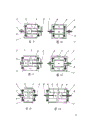
One, import cantilever style (Fig. 9) outward, power is through wheel for inputting 3 inputs as foreign steamer, and central gear comprises a fast pulley 4 and a roulette wheel 5.
Two, interior input cantilever style (Figure 10), power is through wheel for inputting 3 inputs as central gear, and foreign steamer is made up of a fast pulley 4 and a roulette wheel 5.
Three, import balance type (Figure 11) outward, power is through wheel for inputting 3 inputs as foreign steamer, and central gear is made up of two fast pulleys 4 and a roulette wheel 5.
Four, interior input balance type (Figure 12), power is through wheel for inputting 3 inputs as central gear, and foreign steamer is made up of two fast pulleys 4 and a roulette wheel 5.
Five, partly take turns imported (Figure 13), power is through roulette wheel 5 inputs that are positioned at the center, and by another roulette wheel 5 outputs, foreign steamer is fixed.
Six, differential type (Figure 14), power is through wheel for inputting 3 inputs as foreign steamer, and central gear comprises two fast pulleys 4 and two or more roulette wheels 5.
Suitably introduce diameter-changing wheel 6 and replace fast pulley 4 or roulette wheel 5, just can obtain the pattern of giving of the above-mentioned type.
Diameter-changing wheel 6 can be used for belt transmission system, constitutes band class stepless change transmission, and (Figure 17), this moment, the surface of packing 12 can be made into flute profile that is fit to the placement triangular driving band or the shape of placing other driving belt.
In actual applications, device of the present invention can directly connect power engine and working machine (Figure 18), contains wheel 3 and is installed on the motor reel 16, and fast pulley 4 is installed on the motor field frame 17, and roulette wheel 5 connects with working machine input shaft 18.
When directly connecting power engine and working machine (Figure 19), contain wheel 3 and be installed on the motor 16, fast pulley 4 is installed on the working machine housing 19, and roulette wheel 5 is installed on the output shaft 8 by fast pulley 4 endoporus.
Differential type structure can be used for the transmission of vehicle.When on motor bike, using (Figure 20), the shell that contains wheel 3 is shaped on the triangular driving band groove, power engine drives by triangular driving band 20 and contains wheel 3, two fixed semi-wheel 4 are installed in respectively on the vehicle frame 21, two diameter-changing wheels 6 are respectively through two-semiaxle 22 ground-engaging wheels 23, when two diameter-changing wheels 6 are implemented synchronization regulation, vehicle is made straight-line travelling, when two diameter-changing wheels 6 are implemented asynchronous adjusting, vehicle just turns to, when diameter-changing wheel 6 was all consistent with the surface size of fixed semi-wheel 4, vehicle just had zero rotating speed braking.
Compared with the prior art, outstanding advantage of the present invention is can accomplish not change in transmission process and mobile rotatable member, only the surface modulation by single element just can obtain large-scale rotating speed speed ratio variation, and remaining stable contact condition between transmission component, contact trace is the face that contains whole element surface.
Compare with planetary rotating body class stepless speed changes devices, the present invention is simple in structure, and control is convenient, can transmit high-power.
Compare with planetary gear system, the present invention has constant speed ratio and stepless shift function concurrently.
Compare with belt driver, the present invention has expanded slewing range significantly when keeping the flexible drive mechanical property.
Compare with tooth class differential mechanism and clutch differential method, the present invention has realized the pressure differential.
Device and bipolar motor with manufacturing of the present invention are directly installed, and can replace the high multipolar electric motor of the big consumption of volume.
The transmission system that the device made from the present invention replaces vehicle can realize the stepless change of common vehicle, is used to control turning to of two-wheeled vehicle, and is significantly safe and reliable.
With the device transferring power that the present invention makes, working machine can accelerate to full-speed operation from zero rotating speed by on-load gently.Effectively prevent the starting overload of power engine.
The present invention is widely used in the various engineering goods that need transmitting rotary power, improves their existing performance.
The picture explanation of accompanying drawing:
Fig. 1: the compound epicyclic gear train schematic diagram of mechanism that constitutes the flexible roller speed chang gear basic pattern
Fig. 2: the planetary wheel mechanism sketch in the device
Fig. 3: the differential gear train schematic diagram of mechanism in the device
Fig. 4: the axle of flexible roller speed chang gear basic structure pattern is surveyed internal anatomy
Fig. 5: limberoller axial deformation schematic representation
Fig. 6: limberoller radial deformation schematic representation (the A-A section of Fig. 5)
Fig. 7: the reducing wheel shaft is surveyed internal anatomy
Fig. 8: roulette wheel and fast pulley surface circumferentially deploying length schematic representation
Fig. 9: external input cantalever mechanism sketch
Figure 10: inner input Arm Type mechanism sketch
Figure 11: import the balanced body sketch outward
Figure 12: interior input balanced body sketch
Figure 13: partly take turns imported schematic diagram of mechanism
Figure 14: differential type schematic diagram of mechanism
Figure 15: the flexible roller speed chang gear schematic representation that combination cylinder constitutes
Figure 16: the gear unit schematic representation that limberoller and diameter-changing wheel constitute
Figure 17: diameter-changing wheel is used to the schematic representation with transmission
Figure 18: direct coupled inner input structure schematic representation
Figure 19: direct coupled external input-type structure schematic representation
Figure 20: the differential type structural representation on two-wheeled vehicle
Contrast Fig. 1 below, Fig. 4, Fig. 7 describe the details of a kind of concrete device of the present invention's proposition in detail.
This device comprises 5, one retainers 2 of 4, one roulette wheels of 3, one fast pulleys of 1, one wheel for inputting of three limberollers, and housing 11 and some bearings.
The structure of limberoller is same as general common glue rod, cover flexible materials such as wrapping up in rubber or engineering plastics equably in the rigid central spindle outside, its radially chi can bear 10% extrusion-deformation, being drilled with aperture on the retainer 2 cooperates with the axle head of mandrel, the function of retainer 2 is equivalent to the effect of general rolling bearing retainer, roulette wheel 5 and fast pulley 4 all are central gears, the output shaft 8 that connects roulette wheel 5, endoporus through fast pulley 4 passes through, and be installed on the rolling bearing that is fixed on the fast pulley 4, wheel for inputting 3 is foreign steamers, is directly driven by input shaft 7, and input shaft 7 can directly be the output shaft of power engine.
The velocity ratio of said apparatus changes, and can directly change size different fast pulley 4 or roulette wheel 5, also can directly one of two-wheeled be used diameter-changing wheel as shown in Figure 7 to replace, and this surface of taking turns is staggered by three packings made from Steel Spring Plate 12 and constitutes.Be not difficult to derive the velocity ratio of this device by the Der Grundsatz der Maschinen of classics, the difference in size of this velocity ratio and fast pulley 4 and roulette wheel 5 and the amount of deformation of limberoller 1 have direct relation.In fact, when the diameter dimension ratio of limberoller 1 and fast pulley 4 is 0.9: 1, the permission amount of deformation of limberoller 1 is 10% o'clock, and the reduction speed ratio of device just can change in 1/7~0 scope.
The permission transmission power of said apparatus is to be directly proportional with the number and the effective length thereof of limberoller 1.
If the retainer of said apparatus 2 further selects for use rolling bearing to engage with the axle head of limberoller 1, obviously help the raising of device transmission efficiency.
Claims (8)
1, epicyclic gear transmission, has epicyclic friction gear, central gear and foreign steamer, feature of the present invention is, epicyclic friction gear is a limberoller 1, covered to be rolled in the rigid central spindle by rubber or engineering plastics and other flexible materials and make, can bear different radial deformations, fast pulley 4 and output wheel 5 can change radial dimension independently of one another.
According to the speed change gear of claim 1, it is characterized in that 2, the outer surface of limberoller 1 is a continuous cylndrical surface.
According to the speed change gear of claim 1, it is characterized in that 3, the outer surface of limberoller 1 is made of several different cylndrical surface.
According to the speed change gear of claim 1, it is characterized in that 4, it is central gear or foreign steamer simultaneously that two fast pulleys 4 are arranged.
According to the speed change gear of claim 1, it is characterized in that 5, it is central gear or foreign steamer simultaneously that two or more roulette wheels are arranged.
According to the speed change gear of claim 1, it is characterized in that 6, the surface of fast pulley 4 is made of elastic expansion ring 12, evenly breathing.
According to the speed change gear of claim 1, it is characterized in that 7, the surface of roulette wheel 5 is made of elastic expansion ring 12, evenly breathing.
According to the packing of claim 6 or claim 7, it is characterized in that 8, working surface has the groove that can lay driving belt.
Priority Applications (1)
| Application Number | Priority Date | Filing Date | Title |
|---|---|---|---|
| CN85100152A CN85100152B (en) | 1985-04-01 | 1985-04-01 | Flexible roller speed variator |
Applications Claiming Priority (1)
| Application Number | Priority Date | Filing Date | Title |
|---|---|---|---|
| CN85100152A CN85100152B (en) | 1985-04-01 | 1985-04-01 | Flexible roller speed variator |
Publications (2)
| Publication Number | Publication Date |
|---|---|
| CN85100152B CN85100152B (en) | 1985-09-10 |
| CN85100152A true CN85100152A (en) | 1985-09-10 |
Family
ID=4790930
Family Applications (1)
| Application Number | Title | Priority Date | Filing Date |
|---|---|---|---|
| CN85100152A Expired CN85100152B (en) | 1985-04-01 | 1985-04-01 | Flexible roller speed variator |
Country Status (1)
| Country | Link |
|---|---|
| CN (1) | CN85100152B (en) |
Cited By (2)
| Publication number | Priority date | Publication date | Assignee | Title |
|---|---|---|---|---|
| CN104061295A (en) * | 2014-05-29 | 2014-09-24 | 温岭市天工工量刃具科技服务中心有限公司 | Friction planetary reducer |
| CN104769323A (en) * | 2012-05-25 | 2015-07-08 | 詹尼斯高级技术有限公司 | Transmission |
-
1985
- 1985-04-01 CN CN85100152A patent/CN85100152B/en not_active Expired
Cited By (3)
| Publication number | Priority date | Publication date | Assignee | Title |
|---|---|---|---|---|
| CN104769323A (en) * | 2012-05-25 | 2015-07-08 | 詹尼斯高级技术有限公司 | Transmission |
| CN104061295A (en) * | 2014-05-29 | 2014-09-24 | 温岭市天工工量刃具科技服务中心有限公司 | Friction planetary reducer |
| CN104061295B (en) * | 2014-05-29 | 2018-10-16 | 温岭市天工工量刃具科技服务中心有限公司 | Rub planetary reduction gear |
Also Published As
| Publication number | Publication date |
|---|---|
| CN85100152B (en) | 1985-09-10 |
Similar Documents
| Publication | Publication Date | Title |
|---|---|---|
| CN1291265A (en) | Continuously variable transmission | |
| CN1148674A (en) | Automatic Transmission | |
| CN101435493A (en) | Gear engaging drive stepless speed changer | |
| CN1086451C (en) | Reduction gear | |
| CN201526653U (en) | Retractable-piston rod type stepless transmission | |
| CN113374843A (en) | Continuously variable transmission and variable diameter wheel structure and application thereof | |
| CN2315354Y (en) | Cycloidal steel ball speed reducer | |
| WO2000025954A1 (en) | Spindle mechanism of drawer | |
| CN85100152A (en) | Flexible roller speed chang gear | |
| CN104061295A (en) | Friction planetary reducer | |
| CN87209455U (en) | Muff, free teeth, short of teeth differential gearing | |
| CN209671547U (en) | A kind of planetary roller screw transmission device | |
| CN1183523A (en) | Cycloidal ball planet speed reducer | |
| CN212407488U (en) | Planetary roller screw mechanism | |
| CN1030477C (en) | Planetary speed-changing device with less-difference of numler of teeth | |
| CN113790250A (en) | Mechanical stepless speed change method and device | |
| CN1022262C (en) | Concentric wheel | |
| CN1862920A (en) | Electric drive | |
| CN2172818Y (en) | Medium-low speed high-efficient variable drive | |
| CN207278825U (en) | A kind of cylindrical planetary gear differential mechanism | |
| CN108533700B (en) | Continuously variable transmission | |
| CN1726359A (en) | Variable-ratio transmission device | |
| CN2080591U (en) | Eternal toothing type rigid stepless change gear | |
| CN2075729U (en) | Swing moveable teeth speed reducing machine | |
| CN1109567A (en) | Gear type stepless speed variator |
Legal Events
| Date | Code | Title | Description |
|---|---|---|---|
| C06 | Publication | ||
| C13 | Decision | ||
| GR02 | Examined patent application | ||
| PB01 | Publication | ||
| SE01 | Entry into force of request for substantive examination | ||
| C14 | Grant of patent or utility model | ||
| GR01 | Patent grant | ||
| C17 | Cessation of patent right | ||
| CE01 | Termination of patent right |