CN85200213U - Oil burner for industrial furnace - Google Patents
Oil burner for industrial furnace Download PDFInfo
- Publication number
- CN85200213U CN85200213U CN 85200213 CN85200213U CN85200213U CN 85200213 U CN85200213 U CN 85200213U CN 85200213 CN85200213 CN 85200213 CN 85200213 U CN85200213 U CN 85200213U CN 85200213 U CN85200213 U CN 85200213U
- Authority
- CN
- China
- Prior art keywords
- inner liner
- burner
- burner inner
- cylinder
- shell
- Prior art date
- Legal status (The legal status is an assumption and is not a legal conclusion. Google has not performed a legal analysis and makes no representation as to the accuracy of the status listed.)
- Expired - Lifetime
Links
- 238000003466 welding Methods 0.000 claims abstract description 7
- 238000004519 manufacturing process Methods 0.000 claims abstract description 6
- 239000003921 oil Substances 0.000 claims description 21
- 208000005168 Intussusception Diseases 0.000 claims description 14
- 229910000831 Steel Inorganic materials 0.000 claims description 10
- 239000010959 steel Substances 0.000 claims description 10
- XEEYBQQBJWHFJM-UHFFFAOYSA-N Iron Chemical compound [Fe] XEEYBQQBJWHFJM-UHFFFAOYSA-N 0.000 claims description 8
- 229910001220 stainless steel Inorganic materials 0.000 claims description 5
- 239000010935 stainless steel Substances 0.000 claims description 5
- 238000002788 crimping Methods 0.000 claims description 4
- 239000000295 fuel oil Substances 0.000 claims description 4
- 229910052742 iron Inorganic materials 0.000 claims description 4
- 238000009434 installation Methods 0.000 claims description 3
- 229910000805 Pig iron Inorganic materials 0.000 claims 1
- 239000000203 mixture Substances 0.000 claims 1
- 239000011148 porous material Substances 0.000 claims 1
- 238000010438 heat treatment Methods 0.000 abstract description 4
- 239000000446 fuel Substances 0.000 abstract description 3
- 239000000463 material Substances 0.000 abstract description 3
- 238000003723 Smelting Methods 0.000 abstract description 2
- 239000011241 protective layer Substances 0.000 abstract description 2
- 238000002347 injection Methods 0.000 abstract 4
- 239000007924 injection Substances 0.000 abstract 4
- 239000003208 petroleum Substances 0.000 abstract 1
- 238000009826 distribution Methods 0.000 description 8
- 238000002485 combustion reaction Methods 0.000 description 6
- 239000007921 spray Substances 0.000 description 6
- 238000001816 cooling Methods 0.000 description 5
- OKTJSMMVPCPJKN-UHFFFAOYSA-N Carbon Chemical compound [C] OKTJSMMVPCPJKN-UHFFFAOYSA-N 0.000 description 3
- 229910052799 carbon Inorganic materials 0.000 description 3
- 239000011229 interlayer Substances 0.000 description 3
- 238000004939 coking Methods 0.000 description 2
- 230000000694 effects Effects 0.000 description 2
- 239000003350 kerosene Substances 0.000 description 2
- 239000010410 layer Substances 0.000 description 2
- 239000003595 mist Substances 0.000 description 2
- 230000007797 corrosion Effects 0.000 description 1
- 238000005260 corrosion Methods 0.000 description 1
- 239000002283 diesel fuel Substances 0.000 description 1
- 238000004870 electrical engineering Methods 0.000 description 1
- 230000005611 electricity Effects 0.000 description 1
- 238000002474 experimental method Methods 0.000 description 1
- 239000012467 final product Substances 0.000 description 1
- 235000000396 iron Nutrition 0.000 description 1
- 239000007788 liquid Substances 0.000 description 1
- 230000035807 sensation Effects 0.000 description 1
- 239000000758 substrate Substances 0.000 description 1
- 238000009834 vaporization Methods 0.000 description 1
- 230000008016 vaporization Effects 0.000 description 1
- XLYOFNOQVPJJNP-UHFFFAOYSA-N water Substances O XLYOFNOQVPJJNP-UHFFFAOYSA-N 0.000 description 1
Images


Landscapes
- Nozzles For Spraying Of Liquid Fuel (AREA)
- Combustion Of Fluid Fuel (AREA)
Abstract
The utility model relates to an oil burner for industrial furnaces. A flame barrel is formed by stacking and welding a plurality of cylinders with gaps. The diameter of each cylinder is gradually increased to form a horn shape from the fuel injection end to the flame injection end. The gap between the cylinders is also gradually increased from the fuel injection end to the flame injection end. The air of 85% to 93% enters the flame barrel from the gaps between the cylinders, forms a strong cold air protective layer on the inner wall of the flame barrel, and also participates in burning. Thus, the flame barrel is difficult to overheat in full load. The flame barrel has no special requirement on manufacturing materials. The oil burner of the utility model can be used for heating devices of boilers, petroleum heating furnaces, ore furnaces, ingot heating furnaces, smelting furnaces, etc.
Description
The utility model relates to continuous internal combustion flame burner.
The internal combustion burner that has telescopic burner inner liner, great majority only have a spot of air admission hole on burner inner liner, and the cooling of burner inner liner is blown into burner inner liner by cold air and the shell interlayer is realized, and distribution is by realizing near air inlet atomizer or the atomizer.As the burner described in the BP GB2059-594 of approval in 1981 is exactly like this.The Switzerland BBC company of introducing in " gas turbine " book that electrical engineering department gas turbine teaching and research room of Tsing-Hua University writes generates electricity with the cylinder combustion chamber of adopting in the gas turbine, and a kind of aviation burner that burns kerosene of introducing among " jet engine " (" The JET ENGINE " RollsRoyce Limited 1969) is compiled, the hole of air inlet in the oriented tube on burner inner liner, the stack shell by Britain Luo Ersi Roy Si company.Account for the combustion-supporting air quantity of total air inflow below 30% but only enter, all the other air more than 70% spray into from the atomizer end.So, structurally showing as the sleeve gap seldom, lap is little between adjacent two, and the relative lap of underlapped part is longer.All there are the following problems for this burner and previous combustion device: the one, and near the whirlwind the oil nozzle is strong excessively, mist of oil is got rid of to flame tube wall, and the burner inner liner inwall does not have more, stronger air-flow protection; therefore; only be suitable for burning light oil, as burning heavy oil or residual oil, easy coking carbon distribution on the burner inner liner inwall then.The 2nd, flame tube wall is overheated easily, so the material requirement is very high, industrial applicibility is limited to.The 3rd, fuel-flow control is than little.
The utility model purpose is to provide a kind of burner that has improved, can burning heavy oil and even liquid oil plant such as residual oil, and available common iron and general stainless steel manufacturing.
Burner of the present utility model; spray at distribution and air-flow and to have done rational selection on the scheme; combustion air only 7~15% sprays into from the atomizer annex; all the other air of 85~93% by burner inner liner and the shell interlayer air inlet annular space from the burner inner liner along the burner inner liner inwall; axially spray into towards the flame export end; these air had both participated in distribution and had played combustion-supporting effect, made again and formed an air conservation layer (rather than film) on the burner inner liner inwall.In addition, the axial average speed of air-flow in the burner inner liner, very low near atomizer, fast more the closer to outlet, form mist of oil vaporization preferably.
Burner of the present utility model is made up of burner inner liner (1), end plate (2), atomizer (4), shell (3), atomizer block set (5), ring baffle (6) etc.Burner inner liner is formed by the different cylinder intussusception of a plurality of diameters, and the poor of annular space h(big tube inside radius and little tube outer radius arranged between adjacent two cylinders).The drum diameter of forming burner inner liner increases the burner inner liner flare gradually to the flame end from oil inlet end.Annular space h between adjacent two also increases to the flame end gradually from oil inlet end, to guarantee that gas flow rate is high more the closer to outlet in the burner inner liner.Adjacent two cylinder intussusception length L are 20~25mm, the underlapped part length L of each cylinder inner surface ' be 30~50mm.Like this, relative prior art, intussusception is partly long, and guidance quality is good, and intussusception is partly short, and the air that enters forms an air layer, has protected the burner inner liner inwall effectively.Have the hole or the groove of air inlet on the described end plate (2), the gross area of institute's perforate or groove is 7~17% of each annular space gross area of burner inner liner, to guarantee the realization of aforementioned distribution scheme.End plate can be the sandwich plate that is welded with spoke (9) by panel (7) and backboard (8), and the center has atomizer block set installing hole (10), and in the hole of backboard the car internal thread.Area, diameter and thickness are less than base plate, backboard is welded on the burner inner liner, the panel excircle leaves annular space h ' with the internal diameter of tube, having many air inlet skewed slots (11) near the installing hole place on the panel, skewed slot is 20 °~40 ° with radius angle α by the skewed slot starting point, with the panel angle of inclination beta be 20 °~40 °.Having 1~3 annular groove (12), annular groove and panel by the periphery has a tilt angle gamma that makes gas directive circumference, and its value is 30 °~90 °.The closer to the annular groove at center, the inclination angle is more little.Institute's air inlet body protection end face, atomizer are all reinstated in institute inclination angle of opening or oblique angle, produce multiple actions such as laminar flow distribution, and its angle numerical value is through the experiment gained.On backboard (18), have sieve aperture in uniform way.Have on the shell of the utility model burner rectangular as shown air admission hole (13) with its on air guide sieve tray (14) is housed air inlet bucket (16) match.The housing outlet place also has the aperture to equal the ring baffle of burner inner liner flame end external diameter, with the supporting burner inner liner and seal burner inner liner and the interlayer of shell.In order to guarantee gap that air inlet one side and burner inner liner form greater than to side clearance, burner inner liner and shell are eccentric to be installed, and eccentric throw is e.So, open the atomizer block set installing hole (15) on shell, an eccentric distance e away from the shell air admission hole is also arranged.The endoporus of ring baffle (6) has eccentric distance e with outer fenestra.Burner inner liner and shell are connected as a single entity by ring baffle and atomizer block set.The atomizer block set is the cylindrical drum that the middle part has shoulder, and an end car has external screw thread, and the endoporus of shoulder part has annular groove (24), and has installation for the screw of the light oil funnel (22) that adds the usefulness of igniting and the screw of installation igniter plug (23) on shoulder.Owing to taked said structure, the problem that exists in the prior art is solved.Therefore, burner of the present utility model, all available common iron of its burner inner liner, end plate and general stainless steel manufacturing, the form of manufacturing the utility model burner inner liner has multiple, lifts three examples below.
Example one, as shown in figure 11, burner inner liner leaves phase intussusception with gap by the different cylinder of a plurality of diameters, is bumped into steel bar (17) in uniform way on ring week, by welding or riveted joint each circle is solidified as a whole.On the urceolus that studs with the steel bar place, have air inlet compensate opening (18).
Example two, as shown in figure 12, burner inner liner leaves phase intussusception with gap by the different cylinder of a plurality of diameters, and with the inner core welding, making each cylinder affixed is an integral body behind the complete all crimpings of outer sleeve.Arranging staggered air admission holes (19) near opening two on the outer sleeve at crimping place.
Example three, as shown in figure 13, burner inner liner leaves intussusception with gap by a plurality of cylinders, and the connecting ring (20) that equals annular space with a thickness is bumped between adjacent two and welding, and making each cylinder affixed is an integral body.On near the urceolus that connects annulus, open two row's staggered air admission holes (21).
Burner of the present utility model can be used as the heat-needing facilities such as boiler, smith's hearth, steel ingot stove, smelting furnace. The various oil plants such as incendivity diesel oil, kerosene, burning heavy oil, its effect of residual oil are better than general burner. Burner of the present utility model, cooling forms cooling protective layer by the air that enters and realizes that distribution and cooling take into account, and can guarantee that fuel combustion is abundant, can prevent again the overheated and carbon deposit of burner inner liner from annular space. Particularly when the load increase, because distribution capacity also needs corresponding increase, cooling capacity also improves thereupon, and is overheated when avoiding at full capacity, so, the material of manufacturing burner inner liner, less demanding, general steel get final product, and stainless steel is comparatively desirable.
Description of drawings:
Fig. 1 is the structural representation of burner.(1) is burner inner liner; (2) be end plate; (3) be shell, (4) are atomizer; (5) be the atomizer block set; (6) be ring baffle; (14) be the guiding sieve tray; (16) be inlet scoop; (22) be funnel for the light oil that adds the usefulness of igniting; (23) be igniter plug; (24) be annular groove.
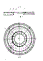
Fig. 2 is the front view of end plate assembly.
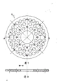
Fig. 3 is I-I cutaway view of Fig. 2.(7) be panel; (8) be backboard; (9) be spoke; (10) be atomizer block set installing hole.
Fig. 4 is a faceplate view.α represents skewed slot and passes through the angle of the radius of skewed slot starting point.(11) be skewed slot; (12) be annular groove.
Fig. 5 is the II-II partial sectional view of expression skewed slot (11) with panel (7) angle, and β represents the angle of skewed slot and plate face.
Fig. 6 is the III-III partial sectional view of expression annular groove (12) with panel (7) tilt angle gamma.
Fig. 7 is the front view of backboard (8).
Fig. 8 is IV-IV cutaway view of Fig. 7.
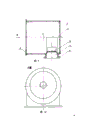
Fig. 9 is the cutaway view of shell (3) assembly, and (13) are the rectangle air admission hole, and (14) are the air guide sieve tray; (15) be atomizer block set installing hole on the shell; (16) be the air inlet bucket; E represents the eccentric throw of atomizer block set installing hole and outer casing centerline.
Figure 10 is that the A of shell (3) is to view (left view).
Figure 11 is the stereogram of burner inner liner embodiment one, and (17) are steel bar, and (18) are the air inlet compensate opening.
Figure 12 is the stereogram of burner inner liner embodiment two, and (19) are air admission hole.
Figure 13 is the stereogram of burner inner liner embodiment three, and (20) are for connecting annulus; (21) be air admission hole.
Embodiment
(1) roll out 5 different cylinders of diameter with 1.5 millimeters stainless steel substrates, the phase intussusception is bumped into the steel bar that thickness is corresponding annular space with being uniformly distributed along the circumference, and welds between per two with a gap, makes each connect into integral body, and its length is 250 millimeters. Corrosion resistant plate with 1.5 millimeters cuts into circular slab, mills out skewed slot according to accompanying drawing 4,5,6 at plectane, and car goes out annular groove, and has diameter greater than the hole of atomizer block set external diameter in the center. Backboard is used 5 millimeters common irons are made, and go out female atomizer block set installing hole at the center car, get out in uniform way sieve aperture on the plate face, and one does air inlet, and two are used as the welding spoke. Be a whole end plate that forms with six roots of sensation spoke with the weldering of panel and backboard. Shell is rolled into general steel plate, opens a rectangle air admission hole on it, and the inlet scoop of making of iron plate welds mutually with it. Burner inner liner and shell are by ring baffle and the atomizer block set is affixed just becomes burner for integral body. Load onto atomizer, supporting oil pressure is 15kg/cm2Oil pump, power is 1.5 kilowatts motor, blast is the blower fan of 400mm water column. Start the blower fan air inlet, oil pump feed sprays into burner inner liner through the atomizer atomizing simultaneously. Ejection continuous flame after the igniting. Through being used for smith's hearth preliminary examination, the burner cold conditions furnace igniting time of smoldering of the present utility model is 2~5 seconds, and quick heating, and the steel part of φ 30 is burnt to 900 ℃ of malleable temperature. The flame that burner sprays is pure, smokeless, bright in vain, even, burning is complete; Under the boundary of smoldering, coefficient of excess air can be low to moderate 1.05. Fuel-economizing 15%~30%, burner housing temperature can be low to moderate 60~150 ℃. Burner inner liner does not have the coking Carbon Deposit Phenomenon.
Claims (12)
1, a kind of used for industrial furnace fuel oil burner, by burner inner liner (1), end plate (2), shell (3), atomizer (4), atomizer block set (5), ring baffle compositions such as (6), burner inner liner (1) is formed by the cylinder phase intussusception that a plurality of diameters do not wait, annular space h (tube inside radius and little tube outer radius is poor greatly) is arranged between adjacent two cylinders, the drum diameter of burner inner liner increases flare from oil inlet end gradually to the flame end, annular space between burner inner liner (1) adjacent two cylinders that it is characterized in that improving also increases to the flame end gradually from oil inlet end, adjacent two cylinder intussusception length L are 20~25 millimeters, each tube inner surface is intussusception length L ' be 30~50 millimeters not, and the gross area of pore that end plate drives into or groove is 7~17% of each annular space gross area of burner inner liner.
2, burner according to claim 1, the burner inner liner (1) that it is characterized in that improving leaves phase intussusception with gap by the different cylinder of a plurality of diameters, ring studs with steel bar (17) on week in uniform way and by welding or riveted joint each cylinder is fixed as one, and has air inlet compensate opening (18) studding with the steel bar place.
3, burner according to claim 1, the burner inner liner (1) that it is characterized in that improving leaves intussusception with gap by a plurality of cylinders, the complete all crimpings of outer sleeve and with riveted joint of the inner core of adjacent intussuscepted or welding, each cylinder is fixed as one, arranging staggered air admission hole (19) near having one to two on the outer sleeve at crimping place.
4, burner according to claim 1, the burner inner liner that it is characterized in that improving leaves intussusception with gap by a plurality of cylinders, the connection annulus (20) that has a thickness to equal annular space is bumped between adjacent two and welds, the affixed one-tenth of each cylinder is whole, connecting ring aligns with outer sleeve, has two row's staggered air admission holes (21) near the urceolus that connects annulus.
5, according to claim 2,3,4 described burners, it is characterized in that end plate (2) for having the sandwich plate of atomizer block set installing hole (10) on it, it is welded with spoke (9) by backboard (8) and panel (7).Panel diameter, thickness are all less than backboard, backboard is welded on the burner inner liner, and annular space h ' is arranged between panel excircle and barrel, has the air inlet sieve aperture on the backboard, having many air inlet skewed slots (11), have 1~3 annular groove (12) on the panel by the periphery near the installing hole place.
6, burner according to claim 5 is characterized in that skewed slot and radius angle α by the skewed slot starting point are 20 °~40 °, and skewed slot and panel angle of inclination beta are 20 °~40 °.
7, burner according to claim 6 is characterized in that annular groove and panel have the tilt angle gamma that makes gas directive circumference, and its value is 30 °~90 °, and near the center annular groove, the inclination angle is more little, and outermost layer annular groove inclination angle is 90 °.
8,, it is characterized in that the central axis of burner inner liner and the central axis of cylindrical outer casing have one to make the gap of air inlet one side shell and burner inner liner greater than the eccentric distance e to side clearance according to claim 1,6,7 described burners.
9, burner according to claim 8 is characterized in that having on the cylindrical outer casing rectangle air admission hole (13), and joins with a rectangle air inlet bucket (16), is welded with the ring baffle (6) that the aperture equals burner inner liner outlet external diameter in the outlet of shell.
10, burner according to claim 9 is characterized in that oil nozzle block set installing hole and the outer casing centerline on the shell has an eccentric distance e away from air admission hole.
11, according to claim 1,10 described burners, it is characterized in that the general stainless steel of burner inner liner, shell is with common iron or pig iron manufacturing.
12, according to claim 1,2 described burners, it is characterized in that the atomizer block set is the cylindrical drum that the middle part has shoulder, one end car has external screw thread, the endoporus of shoulder part has annular groove (24), and has on shoulder for the screw of the light oil funnel (22) that the usefulness of igniting is installed and the screw of installation igniter plug (23).
Priority Applications (1)
| Application Number | Priority Date | Filing Date | Title |
|---|---|---|---|
| CN 85200213 CN85200213U (en) | 1985-04-01 | 1985-04-01 | Oil burner for industrial furnace |
Applications Claiming Priority (1)
| Application Number | Priority Date | Filing Date | Title |
|---|---|---|---|
| CN 85200213 CN85200213U (en) | 1985-04-01 | 1985-04-01 | Oil burner for industrial furnace |
Publications (1)
| Publication Number | Publication Date |
|---|---|
| CN85200213U true CN85200213U (en) | 1985-09-10 |
Family
ID=4796609
Family Applications (1)
| Application Number | Title | Priority Date | Filing Date |
|---|---|---|---|
| CN 85200213 Expired - Lifetime CN85200213U (en) | 1985-04-01 | 1985-04-01 | Oil burner for industrial furnace |
Country Status (1)
| Country | Link |
|---|---|
| CN (1) | CN85200213U (en) |
Cited By (3)
| Publication number | Priority date | Publication date | Assignee | Title |
|---|---|---|---|---|
| CN104024734A (en) * | 2012-08-07 | 2014-09-03 | 日野自动车株式会社 | Burner for exhaust gas purification devices |
| US9746175B2 (en) | 2012-08-07 | 2017-08-29 | Hino Motors, Ltd. | Burner |
| US9765662B2 (en) | 2012-08-13 | 2017-09-19 | Hine Motors, Ltd. | Burner |
-
1985
- 1985-04-01 CN CN 85200213 patent/CN85200213U/en not_active Expired - Lifetime
Cited By (3)
| Publication number | Priority date | Publication date | Assignee | Title |
|---|---|---|---|---|
| CN104024734A (en) * | 2012-08-07 | 2014-09-03 | 日野自动车株式会社 | Burner for exhaust gas purification devices |
| US9746175B2 (en) | 2012-08-07 | 2017-08-29 | Hino Motors, Ltd. | Burner |
| US9765662B2 (en) | 2012-08-13 | 2017-09-19 | Hine Motors, Ltd. | Burner |
Similar Documents
| Publication | Publication Date | Title |
|---|---|---|
| CN108894893A (en) | Rocket punching press combined engine Film cooling Rocket ejector motor power room | |
| CN101446413A (en) | Combined type multi-injector burner | |
| CN206018619U (en) | A kind of multi fuel multiple-layer stacked honeycomb fashion burner apparatus | |
| CN108266727B (en) | Ultra-low NO of internal circulation of flue gas x Exhaust gas burner | |
| CN201203108Y (en) | Swingable Pulverized Coal Burner with Micro-oil Thermal Enhanced Spout | |
| CN101178175A (en) | Lean oil heat intensified firing actuating apparatus of pulverized coal boiler | |
| CN102424910B (en) | Combustion nozzle for whole hydrogen bell-type annealing furnace, and waste hydrogen introduction and combustion method adopting the same | |
| CN109539561A (en) | A kind of fuel oil type full-automatic air heater | |
| CN85200213U (en) | Oil burner for industrial furnace | |
| CN108895446B (en) | Odd number circulation ignition high-efficiency energy-saving ultralow NO X Gas burner | |
| CN108443874B (en) | Combustor and combustion head thereof | |
| CN212481292U (en) | Split type hot-blast type low-nitrogen gas burner | |
| CN2137574Y (en) | Quick-baking device for ladle | |
| CN109575997A (en) | A kind of high-effective gas burner and its application method with fine coal premix | |
| CN85200338U (en) | Inverted cased pipe residual burner | |
| CN88203589U (en) | Multifunctional adjustable shunting oil (gas) burner | |
| CN2800078Y (en) | Vortex combined burner with flammable powder as fuel | |
| CN2145913Y (en) | oil fuel combustion flame tube | |
| CN212565764U (en) | Double-preheating split type burner | |
| CN2527867Y (en) | Oil-less direct ignition burner for coal powder-fired boiler | |
| CN222186942U (en) | Low-calorific-value gas air duct burner | |
| CN101782239A (en) | Oil-saving ignition method for fault coal and pulverized coal burner applying method | |
| CN85200214U (en) | Diesel oil burner for industrial furnace | |
| CN204554815U (en) | A kind of blast furnace gas self preheating burner | |
| CN105737149B (en) | Coal gas of high temperature burner special |
Legal Events
| Date | Code | Title | Description |
|---|---|---|---|
| C06 | Publication | ||
| PB01 | Publication | ||
| C14 | Grant of patent or utility model | ||
| GR01 | Patent grant | ||
| C15 | Extension of patent right duration from 15 to 20 years for appl. with date before 31.12.1992 and still valid on 11.12.2001 (patent law change 1993) | ||
| RN01 | Renewal of patent term | ||
| C53 | Correction of patent for invention or patent application | ||
| COR | Change of bibliographic data |
Free format text: CORRECT: PATENTEE; FROM: YAN MENGQIU TO: YANSHI BURNER FACTORY |
|
| CP03 | Change of name, title or address |
Address after: 414000 Hunan, Yueyang province wins South Road screw port Patentee after: Yanshi Burner Factory Address before: No. 20, lane, King's house, north gate, Hunan, Changsha Patentee before: Yan Mengqiu |
|
| C17 | Cessation of patent right | ||
| CX01 | Expiry of patent term |