CN85201517U - Drill-tap holder being able to safely change - Google Patents
Drill-tap holder being able to safely change Download PDFInfo
- Publication number
- CN85201517U CN85201517U CN 85201517 CN85201517U CN85201517U CN 85201517 U CN85201517 U CN 85201517U CN 85201517 CN85201517 CN 85201517 CN 85201517 U CN85201517 U CN 85201517U CN 85201517 U CN85201517 U CN 85201517U
- Authority
- CN
- China
- Prior art keywords
- inserting handle
- sleeve
- spring
- holder
- face key
- Prior art date
- Legal status (The legal status is an assumption and is not a legal conclusion. Google has not performed a legal analysis and makes no representation as to the accuracy of the status listed.)
- Granted
Links
- 238000010079 rubber tapping Methods 0.000 claims abstract description 17
- 229910000831 Steel Inorganic materials 0.000 claims description 16
- 239000010959 steel Substances 0.000 claims description 16
- 238000013507 mapping Methods 0.000 claims description 3
- 238000007789 sealing Methods 0.000 claims description 3
- 238000005553 drilling Methods 0.000 abstract description 6
- 238000004458 analytical method Methods 0.000 description 3
- 230000005540 biological transmission Effects 0.000 description 2
- 238000006243 chemical reaction Methods 0.000 description 2
- 230000000694 effects Effects 0.000 description 2
- 238000000926 separation method Methods 0.000 description 2
- 206010038743 Restlessness Diseases 0.000 description 1
- 238000004519 manufacturing process Methods 0.000 description 1
- 238000000034 method Methods 0.000 description 1
- 238000003825 pressing Methods 0.000 description 1
- 230000003068 static effect Effects 0.000 description 1
- 238000003756 stirring Methods 0.000 description 1
Images


Landscapes
- Gripping On Spindles (AREA)
Abstract
The utility model relates to the safe fast changing tapping holder of a machine tool, and solves the drawback that the present drilling tapping holder breaks the tap because the changing mechanism is forgotten to be shifted. The drilling tapping holder changes the shifting of the changing mechanism of the prior art into the end surface key clutch changing mechanism. The length of the taper shank drill head or the drill holder inserting handle is shorter than the length of the tap inserting handle. When the taper shank drill head or the drill holder inserting handle are respectively inserted into a holder, the drill holder inserting handle does not leave the clutch, but the tap inserting handle can push the clutch aside, and thus the automatic changing of the drilling and the tapping is realized. The utility model realizes the safe and fast changing, and simultaneous has simple structure. The carry-over moment is greater than the carry-over moment of the original structure.
Description
A kind of safe quick change boring tap holder that relates to machine tool accessories, already used safe quick change changes the drilling and tapping chuck, chuck as Minghang Tool General Factory, Shanghai's production, it has one and pulls out key and a ratchet mechanism, during boring, be used for pulling out key and pull out to bore position, socket for taper shank is given sleeve and drill bit by ratchet with transmission of power.During tapping, will pull out key and pull out to the tapping position, socket for taper shank is given sleeve and screw tap by friction plate with transmission of power.When load surpassed setting, friction plate can skid automatically, played the effect of protection screw tap.But because in this product; boring, tapping conversion need to pull out key with manual operation; in use; regular meeting forgets to pull out or mistake is pulled out key during the operator; its result or when tapping, fracture screw tap; or skidding takes place when boring; though thereby safety by name, quick change, boring, tap holder; in fact still certain unsafe factor lies dormant; the positioning sleeve of this product adopts exposed spring structure; profile is not too attractive in appearance, and Chang Fashengyin dismounting back assembling is inaccurate and cause the accident of damaging the drilling and tapping chuck.
Purpose of the present invention is exactly at the existing shortcoming of above-mentioned chuck, propose a kind of through having improved, novel safe quick change tapping boring combination chuck, can eliminate the workman fully and forget to pull out or miss the unsafe factor that pulls out key and cause the accident, realize real safety, quick change at the boring of this kind of use, tap holder.
Boring of the present invention, tapping mapping device are by the straight end-face key clutch, and screw tap inserting handle, drill chuck inserting handle or Mohs drill bit inserting handle constitute.Drill bit inserting handle or Mohs drill bit inserting handle, distance from the center line of handle circular groove on one's body to drill bit inserting handle end less than the screw tap inserting handle on from the center line of circular groove the distance to the end of screw tap inserting handle.When boring, after locking ball snaps in the circular groove on drill chuck inserting handle or the Mohs drill bit inserting handle, there is certain distance its end from the lower surface of straight end-face key clutch, push up not open the straight end-face key clutch, so socket for taper shank connects sleeve And by the straight end-face key clutch and transmits bigger power.During tapping; after locking ball snaps in the circular groove on the screw tap inserting handle; its end contacts And with the lower surface of straight end-face key clutch straight end-face key is backed down; cut off power and passed to the circuit of screw tap inserting handle, so power can only come transferring power to give the screw tap inserting handle through the friction plate in the chuck, when the tapping resistance overrate through end face clutch; friction plate just skids, thereby has protected screw tap, workpiece and lathe.
The present invention has also done improvement to the positioner of drill bit inserting handle and screw tap inserting handle.
On the wall of sleeve proximal end portion, have a through hole, placement positioning steel ball in the hole, be with a positioning sleeve on its outer surface, this positioning sleeve is the torus that annular groove is arranged in, the groove of this positioning sleeve and the outer surface of sleeve constitute the annular chamber of a sealing, lay a spring in the chamber, one end of the spring outer face interior with locating grooving contacts, the other end of spring promptly contacts with bottom face in the locating slot away from an end of sleeve ends, entad curved 90 ° of the steel wire heads of this end spring, penetrate location hole of the spring in sleeve wall, positioning sleeve can be done limited moving along axis, when free state, the internal face of positioning sleeve contacts with steel ball, makes steel ball can not be more outwards move and play the role of positioning.
Advantage of the present invention is tangible, owing to cancelled and pulled out key, adopted the straight end-face key clutch configuration, when the drilling and tapping conversion, must change screw tap inserting handle and drill chuck inserting handle, will make combination of straight end-face key clutch or separation automatically, needn't manually stir key, can avoid artificial mistake to pull out and the screw tap that fractures.This constitutional detail is few and simple, easily manufactured, and carry-over moment is also greater than the original structure in the prior art.The built-in spring structure of positioning sleeve, good looking appearance and have certain security performance, being ignorant of this chuck structure person can not dismantle, and has avoided unrest to tear open and cause the accident.
Description of drawings:
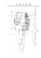
Fig. 1 is the front view of safe quick change boring tap holder of the present invention, and the part has been done to cut open
Look.
Fig. 2 be the Mohs drill bit inserting handle used of safe quick change boring tap holder of the present invention just
View, part have been done to analyse and observe.
Fig. 3 is facing of the drill chuck inserting handle used of safe quick change boring tap holder of the present invention
Figure, the part has been done to analyse and observe.
Fig. 4 is the front view of the screw tap inserting handle used of safe quick change boring tap holder of the present invention,
The part has been done to analyse and observe.
Be described in detail a most preferred embodiment of the present invention below in conjunction with accompanying drawing.
As shown in Figure 1, parts (1) are socket for taper shank, it is made of taper shank (7) and the collet head (10) that is hollow form, be shaped on a homalocephalus (20) with certain-length in the end of taper shank (7), be shaped on certain-length external screw thread (21) in collet head (10) end, be shaped on internal spline (14) within it on the wall, have the keyway (25) that is symmetrical in sleeve axis within it on bottom surface (23), the degree of depth and the width of keyway (25), length all should be slightly larger than the height of straight end-face key (16), width and length, have in keyway (25) bottom one with collet head (10) coaxial line, the aperture is slightly larger than the external diameter of spring (18), is slightly less than the width of keyway (25) and has the hole (27) of certain-length.Parts (4) are sleeve, on the outer wall of sleeve (4), be shaped on external splines (26), on the bottom surface (38) of sleeve (4), have keyway (28), its degree of depth is less than the width and the length of straight end-face key (16), be symmetrical in the keyway (28) of axis on both sides, the side of keyway both sides becomes the fan type, its angle is 55 °, the square opening (29) that certain-length is arranged in the center of sleeve section bottom, there is the taper hole (30) of a placement steel ball (6) at its close end place, and the diameter at the nearly inwall of taper hole place is less than the diameter of steel ball (6).Parts (2) are nut, be shaped on the internal thread of certain-length within it on the wall, this internal thread matches with external screw thread (21) on the socket for taper shank (1), be carved with in order to regulate the scale of torque size at the edge of its outer surface, one circular groove is arranged on the internal face of nut (2) one ends, circular groove on this circular groove and outside fix circle (9) outside wall surface constitutes the spherical raceway of an encirclement steel ball (8), the raceway slightly larger in diameter is in the diameter of steel ball (8), and nut (2) is that the method with heat expansion is assembled to steel ball (8) and goes above.Parts (3) are positioning sleeves, this positioning sleeve is the torus that annular groove is arranged in, it is enclosed within the head of sleeve (4), the internal diameter of two ends face is slightly larger than the external diameter of sleeve (4), the outer surface that can move groove in this positioning sleeve and sleeve outside sleeve constitutes the annular chamber of a sealing, lays spring (5) in the chamber.One end of spring (5) contacts with an end (33) of location grooving, the other end contacts with side (32), the steel wire head of this spring entad bends 90 °, penetrate the location hole of the spring that aperture on sleeve (4) wall is slightly larger than steel wire diameter, its position should make the internal face (31) of positioning sleeve can prop up steel ball (6).Alignment pin (17) is used for retainer spring (18), and itself and straight end-face key (16) are the tight fit relation.Parts (12) are the static friction sheet, and it is a circular ring plate, are being distributed with the external splines that matches with internal spline (24) on collet head (10) inwall on its excircle.Internal diameter is greater than the external diameter of sleeve (4).Movable friction plate (13) also is a circular ring plate.Make the internal spline that the external splines (26) on same sleeve (4) periphery matches on the inner periphery of movable friction plate (13), its outside diameter is less than the top diameter of the internal spline on the socket for taper shank head (10)
Shown in Figure 3 as Fig. 1 Fig. 2, the center line (36) of the circular groove (34) on the drill chuck inserting handle (19) (or Mohs drill bit inserting handle (35)) to the distance of the end (37) of drill chuck inserting handle (19) (or Mohs drill bit inserting handle (35)) should be less than the center line of hole (30) distance to the bottom surface (39) of keyway (28).The distance of (42) should be slightly larger than the distance of the center line in hole (30) to the bottom surface (38) of sleeve (4) to the center line (41) that screw tap inserting handle (22) is gone up circular groove (40) to the end.Sleeve (4) bottom surface (38) contacts with socket for taper shank inner bottom surface (23), in the annular space of socket for taper shank (1) and sleeve (4), socket for taper shank inner bottom surface (23), interior centring ring (15), friction plate (12), (13), dish spring (11) outside fix circle (9) are arranged in order contact.Wherein, decide friction plate (12) and be fixed on the socket for taper shank (1), movable friction plate (13) is fixed on the sleeve (4), and friction plate (12), the adjacent a slice of (13) a slice are placed at interval.By the power of adjusting nut (2) with adjusting pressing friction sheet, thus the size of the moment of friction that adjusting is transmitted.Spring (18) is arranged in the hole (27), and the one end contacts with at the bottom of the hole, and the other end contacts with the side (43) of straight end-face key (16) in being arranged at keyway (25), (28).The keyway (28) of the keyway (25) on the endoporus bottom surface of socket for taper shank (1), sleeve (4) end face, straight end-face key (16), spring (18) and alignment pin (17) have been formed the straight end-face key clutch.When chuck is used to hole, because of drill chuck inserting handle (19) or Mohs drill bit inserting handle (35) top less than straight end-face key (16), under the effect of spring (18), straight end-face key is stuck in keyway (25), (28) between, the power of lathe is just passed to straight end-face key (16) by socket for taper shank (1), pass to keyway (28) again, drive sleeve (4) and pass to drill bit again, when tapping, screw tap inserting handle (22) upwards pushes up straight end-face key (16) from keyway (28), this moment the straight end-face key clutch separation, lathe power just can only be passed to sleeve (4) by friction plate, has passed to screw tap again.
Claims (4)
1, a kind of safe quick change boring tap holder that relates to machine tool accessories, it comprises socket for taper shank (1), sleeve (4), nut (2), friction plate (12), (13), drill chuck inserting handle (19), Mohs drill bit inserting handle (35), screw tap inserting handle (22), inserting handle detent mechanism and threading drill bit mapping device
The invention is characterized in that described tapping boring mapping device is by the straight end-face key clutch, screw tap inserting handle (22), drill chuck inserting handle (19) or Mohs drill bit inserting handle (35) constitute, the distance of (37) is less than the center line of hole (30) distance to the bottom surface (39) of keyway (28) to the end from the center line (36) of circular groove (34) for drill chuck inserting handle or Mohs drill bit inserting handle, and the distance of (42) is slightly larger than the distance of the center line (41) of hole (30) to the bottom surface (38) of sleeve (4) to the center line (41) that screw tap inserting handle (22) is gone up arc groove (40) to the end.
2, safe quick change tap holder as claimed in claim 1, it is characterized in that described straight end-face key clutch is by the keyway (25) on socket for taper shank (1) the endoporus bottom surface, the keyway (28) of sleeve (4) end face, be stuck in the straight end-face key (16) in keyway (28) and (25), (16) And are positioned at the spring (18) on the straight end-face key (16) by alignment pin (17) and are formed with the friction tight alignment pin of straight end-face key (17) to withstand straight end-face key.
3, safe quick change boring as claimed in claim 1 or 2, tap holder, it is characterized in that described inserting handle detent mechanism is by spring (5), positioning sleeve (3), sleeve (4) constitutes, positioning sleeve (3) is in one the annular groove torus to be arranged, it is enclosed within the head of sleeve (4), the internal diameter of two ends face is slightly larger than the external diameter of sleeve (4), the groove of this positioning sleeve and the outer surface of sleeve constitute the annular chamber of a sealing, lay spring (5) in the chamber, one end of spring (5) contacts with the side (33) of location grooving, the other end contacts with side (32), the steel wire head of this end spring entad bends 90 °, penetrates spring (5) locating hole that on sleeve (4) wall aperture is slightly larger than steel wire diameter.
4, safe quick change boring as claimed in claim 1 or 2.Tap holder, it is characterized in that on the inwall of described nut (2) one ends, a circular groove being arranged, circular groove on this circular groove and outside fix circle (9) outside wall surface constitutes the raceway of an encirclement steel ball (8), its slightly larger in diameter is equipped with a circle ball (8) in the diameter of steel ball (8) in the raceway.
Priority Applications (1)
| Application Number | Priority Date | Filing Date | Title |
|---|---|---|---|
| CN 85201517 CN85201517U (en) | 1985-05-09 | 1985-05-09 | Drill-tap holder being able to safely change |
Applications Claiming Priority (1)
| Application Number | Priority Date | Filing Date | Title |
|---|---|---|---|
| CN 85201517 CN85201517U (en) | 1985-05-09 | 1985-05-09 | Drill-tap holder being able to safely change |
Publications (1)
| Publication Number | Publication Date |
|---|---|
| CN85201517U true CN85201517U (en) | 1986-07-30 |
Family
ID=4797564
Family Applications (1)
| Application Number | Title | Priority Date | Filing Date |
|---|---|---|---|
| CN 85201517 Granted CN85201517U (en) | 1985-05-09 | 1985-05-09 | Drill-tap holder being able to safely change |
Country Status (1)
| Country | Link |
|---|---|
| CN (1) | CN85201517U (en) |
-
1985
- 1985-05-09 CN CN 85201517 patent/CN85201517U/en active Granted
Similar Documents
| Publication | Publication Date | Title |
|---|---|---|
| US2522217A (en) | Composite bit device for screw drivers and the like | |
| US5649791A (en) | Apparatus and method for boring a hole in a broken bolt | |
| US7331738B2 (en) | Drill adapter for a power screwdriver | |
| US4296656A (en) | Driver bit attachment | |
| JPH04211722A (en) | Releasable locking mechanism | |
| BR102014025491A2 (en) | drilling apparatus and method | |
| US5101698A (en) | Screw head depth limiter | |
| GB2329208A (en) | Indexing percussive drilling bit | |
| JPS61188041A (en) | Main and sub tool shanks for machine tool | |
| US4612998A (en) | Retracting positive feed drill with idle mode | |
| ES257577U (en) | Drilling unit used to manufacture undercut holes. | |
| US5746552A (en) | Adjustable drill bushing | |
| US2990189A (en) | Socket connecting means for a rotary impact tool | |
| JP2572061B2 (en) | Drilling device for undercutting blind holes | |
| CN85201517U (en) | Drill-tap holder being able to safely change | |
| JP3115514B2 (en) | Chuck holder mounting device | |
| AU650110B2 (en) | Drilling apparatus for producing drilled holes with undercuts | |
| EP0662363B1 (en) | Chucking apparatus | |
| US4284285A (en) | Self-adjusting rotary chuck | |
| US4540319A (en) | Drilling device for removing a spot-welded portion | |
| US4984844A (en) | Safety key for toolroom lathe chuck | |
| US3829230A (en) | Tapping attachment adapted for numerical control | |
| JP2520546B2 (en) | Core drill | |
| CA2181102A1 (en) | Universal tool holding device for use with a power-driven, rotatable spindle machine | |
| EP0083860A2 (en) | A drive attachment for a power drill or like tool |
Legal Events
| Date | Code | Title | Description |
|---|---|---|---|
| C06 | Publication | ||
| PB01 | Publication | ||
| C14 | Grant of patent or utility model | ||
| GR01 | Patent grant | ||
| C15 | Extension of patent right duration from 15 to 20 years for appl. with date before 31.12.1992 and still valid on 11.12.2001 (patent law change 1993) | ||
| RN01 | Renewal of patent term | ||
| C17 | Cessation of patent right |