Method and apparatus for coating and curing containers
Currently, some soft drinks (e.g., soda pop) are typically contained in a plastic container called a PET container. In addition, other plastic containers are also being used or are being developed for packaging beer, salad dressings and other food products, as well as for packaging cosmetics, pharmaceuticals and other materials. The plastic containers have a short shelf life, and after a short time the soda loses its dissolved carbon dioxide, and other products lose their freshness, making them no longer available to consumers. It is now possible to apply the barrier coating to the outside surface of the PET container, which reduces the gas permeability of the plastic and thus keeps the beverage in its aerated condition for a longer period of time, extending the shelf life of the package. Other types of barrier coatings are used or are being developed for other types of plastic containers, again to extend the shelf life of such packages.
The present invention relates to a method and apparatus for coating and curing plastic containers, and also includes transporting plastic containers and moving them through the coating and curing apparatus in a rapid and efficient manner to ensure proper coating and proper curing of the containers, so that the coated and cured containers take on all of the benefits of extended shelf life afforded by the barrier coating on the outer surface.
The method and apparatus for coating and curing containers according to the invention preferably form part of a complete plastic container manufacturing line comprising equipment for forming, washing, coating, curing, printing or labelling and filling the containers with the packaged product. These equipment are connected by container conveyors, single file lines and carriers to achieve the high speed operations necessary for economical and high-performance production.
In the case of the present invention, it is preferred to feed the containers to the coating and maturation apparatus using a container transfer system as disclosed in co-pending patent application No. 647297, filed on 9/4/1984. Such transfer systems generally comprise a conveyor for transferring uncoated plastic containers in a substantially horizontal position to a transfer machine equipped with a conveyor belt with a grid and moving in time with a set of carriers. A suitable carrier is disclosed in co-pending patent application No. 657244 filed on 3.10.1984 entitled "rotating and retractable container gripper and conveyor therefor". The carrier is connected to the neck or mouth of each container and carries them through the coating and curing system, and then transports the coated and cured containers to a conveyor for transport. The carrier effectively seals the mouth of each container so that the barrier coating is limited to coating the outer walls of the containers. The carriers are carried by their conveyors to the coating booth where they position the containers in the proper position within the coating booth and rotate the containers to ensure that all of the coating is on the containers and evenly distributed thereon, which in turn provides the proper rotational motion so that the coating does not hang or drip and remains evenly distributed. After the coating is applied, the containers are carried by a carrier into a curing oven and passed in the oven in a serpentine reciprocating up and down to complete the curing process.
In a further aspect of the invention, the coated container is passed through a curing oven with the barrier coating on its outer surface subjected to a combination of radiation curing and convection curing. The carrier carries the containers in a serpentine path that reciprocates up and down through the furnace. Each vertical channel forms an independent chamber for curing the selected radiation over the entire coating surface of the container. In addition, hot air is supplied to each vertical channel for convection ripening of the containers. The curing oven may be equipped with one or more vertical channels depending on the desired throughput and residence time in the oven required for barrier coating.
In a preferred embodiment, the lower portion of each vertical channel is provided with a radiation source for radiation curing. Each vertical channel has a flow of recirculating air which is heated by a radiation source to a preselected temperature to convectively cook the container in the upper portion of the channel. A control system is provided to regulate the flow rate and quantity of maturation air to ensure proper maturation.
The curing oven may include one or more sections having different curing conditions, such as temperature and humidity, to provide a curing regime specifically tailored to the type of container and coating desired.
Each section may be equipped with a humidification system to meet the humidity necessary for proper curing of a particular coating.
The use of the oven of the present invention with both radiation curing and convection curing allows the barrier coating on the outer surface of the container to be simultaneously cured and cured. Furthermore, the curing of the coating is from the inside outwards, so that "skinning" can be avoided, a phenomenon which occurs when the outer surface first solidifies and cures, thus preventing further curing of the substrate. This skinning results in a "mud-cracking" phenomenon when the bottom layer emerges. Containers that have not been normally matured are unusable.
It is an object of the present invention to provide a method and apparatus for coating and curing containers, particularly plastic containers, which includes the steps of carrying the container and exposing substantially all of its exterior surface, applying a barrier coating to the exterior surface of the container, and then curing the coating so that it is available for filling with a consumer product.
It is a further object of the present invention to hold, rotate, and move each container through the coating and curing process.
It is a further object of the present invention to clamp each container at its open end so that the entire outer surface can be coated, while the container neck and interior is shielded from the coating and the coating can be cured.
It is a further object of the present invention to provide a carrier system to receive, hold, rotate, and move containers in a substantially horizontal position along a serpentine path through an application chamber and a curing chamber.
It is a further object of the present invention to provide a means for rotating the containers as they are carried through the application and maturation chambers.
It is a further object of the present invention to provide a method and apparatus for rotating a container at high speeds while it is being sprayed in a coating booth to ensure even distribution of the coating and then substantially reducing its rotational speed to maintain and control the thickness of the coating so that it does not drip or hang down.
It is a further object to provide a system as aforesaid which can select the speed of the line according to the required throughput, for example from twenty-five feet to one hundred fifty feet per minute.
It is another object of the present invention to cure the barrier coating on the container from the inside out.
It is another object of the present invention to provide a curing means for the coating of the container with radiant heat and convective air.
It is another object of the present invention to provide recirculating convective air heated to a preselected temperature by a radiation source.
Another object is to provide a multi-stage curing oven that varies the curing conditions for different containers and different coatings requirements.
Another object of the present invention is to provide radiant heat projectors installed at the lower portion of each channel of a curing oven, which are distributed in such a manner that the radiation irradiates the entire surface of the container.
Another object is to provide a humidification system for special coatings that need to reach high temperatures before the evaporation curing process is started.
It is a further object of the present invention to provide a furnace designed in a modular unit that is convenient to manufacture, transport, and assemble within a container processing plant.
Other and further objects will be apparent to those skilled in the art upon reading this specification or will become apparent when the invention is put into practice.
For the purpose of illustration, a preferred embodiment of the invention has been chosen and described in connection with the accompanying drawings. These figures are:
FIG. 1 is a schematic view of the method and apparatus of the present invention, including a container loading zone, a coating zone, a maturation zone, and a container unloading zone, all connected by a conveyor system shown in dotted lines.
Fig. 2 is a fragmentary plan view of a container transfer system including an infeed conveyor, a time-controlled screw conveyor, a transfer machine, and a container holding device conveyor, which system may be used in conjunction with the present invention.
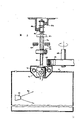
Fig. 3 is a side view showing the container as it is moving through a coating booth, and also showing the mechanism for rotating the container.
FIG. 4 is a plan sectional view of a container holding device carrying a container through a coating chamber.
Fig. 5 corresponds to fig. 4 and shows the relative position of the container holding device without the container.
FIG. 6 is a front view of a aging oven assembled by a plurality of units according to the present invention.
Fig. 7 is a cross-sectional side view showing the internal arrangement of one curing channel and the recirculation channel of convective air.
Fig. 8 is an internal plan view of the combination unit of fig. 7, which shows the distribution of the plate-type radiant heat projectors according to the shape of the matured containers.
FIG. 9 is a plan view of the combination unit of FIG. 6, which shows the distribution of plate-type radiant heat projectors in the channels of the adjacent aging furnaces.
Figure 1 schematically illustrates the invention and includes an endless conveyor 10 (shown in dotted lines) which loads containers from a loading station 12, transports them to a release agent application chamber 14, and then to a curing chamber 16 where the coating is cured. The containers are thereafter conveyed to a discharge station 18 from which they are carried by a conveyor to the next process step, where they are filled with food consumables such as soda, or food products such as ketchup, salad dressing, etc. The containers are transported in a horizontal manner on an endless conveyor belt and in the coating and curing chambers through a roundabout path, the process of which will be described in more detail below.
A container transfer system suitable for use with the present invention is disclosed in the already mentioned patent application No. 647297. As shown in fig. 2, it includes a feed conveyor 20 which conveys containers sequentially through a guide chute 24 and a timing screw conveyor 26 to a transfer conveyor 28. The transfer machine includes an inlet conveyor 30 for positioning each incoming container within the grid 32 and a cellular container conveyor 34 which supports and positions the containers from an upright position to a horizontally disposed position guided by container neck guides 36. The shape and arrangement of the lattice of such a cellular conveyor is suitable for the container shape shown in fig. 2. Of course, the lattice form of the transfer machine can be modified as desired for different container shapes, including cylindrical containers as described in co-pending patent application No. 647297.
The action of the container carrier 10 is coordinated in time relation with the transfer machine 28 and includes a container carrier 38 for engaging and gripping the open ends of the containers and carrying them into and through the coating and curing chambers while maintaining them substantially horizontal. Each container carrier moves along path a, parallel to the container moving on the transfer machine along path B, in a time and space relationship coordinated therewith. In addition, the container carriers are aligned with each container so that each carrier can telescope over and grip the neck of a container as long as it extends through the space between the two parallel lanes. After the carrier has gripped the containers tightly, the transfer machine and the tracks of the carrier can be separated, and the carrier carries the containers along for subsequent coating and curing processes.
Details of the container carriers are disclosed in co-pending patent application No. 647297, so that certain knowledge is sufficient for the present application. Each carrier is mounted on an endless conveyor 10 and comprises an inner sleeve 40 and an outer sleeve 42 which is rotatably movable relative to the inner sleeve 40 by means of a rotatable joint 44 and which is provided at its end with a collet 46 whose open end is connectable to each container. The inner and outer sleeves are axially slidable on their central rod 48. A cam follower 50 on the inner sleeve cooperates with a cam 52 to move the sleeve axially.
During loading of the container into the carrier 38, the cam follower 50 slides over the cam surface 54 of the cam 52, thereby pushing the carrier axially out against the force of its internal spring 56 (see fig. 4). Since the actions of the collet 46 and the container are in coordinated registration in time, the collet sleeves and grips the container as shown on the left side of fig. 2. The carrier 38A (fig. 2) not connected to the container is pushed back at the cam gap 58 (fig. 2) by the spring force of its internal spring 56 and follows a different path than the carrier with the container during the subsequent coating and curing process.
Figures 4 and 5 show the position and operation of the gripping means with the container on the cam surface 54 in the active stroke, respectively. In fig. 4, container 22 is brought into application booth 14 by container holding apparatus 38 and barrier coating 60 is applied thereto by nozzle 62. The position of the container within the application chamber is determined by the cam surface 54 against the cam follower 50. A belt pulley 66 mounted on one side of the carrier and driven by a shaft 68 carries a drive belt 64. The belt contacts the wheel 70 and rotates the outer sleeve 42 and the container within the coating chamber. The rotation of the container is to ensure that the container receives the sprayed coating material uniformly and to prevent the coating material from hanging or dripping before curing.
It can be seen that since the container is held in place by the neck, the entire outer surface of the container is sprayed with the coating. In addition, the neck itself and the interior of the container are shielded since these areas do not require a coating.
A pre-chamber 72 houses a pipe 74 which sprays a spray of water into the application chamber to maintain the desired humidity in the chamber and prevent paint from entering the pre-chamber. In fig. 4 and 5 the container carriers are supported in a horizontal position for vertical movement through the coating booth in a cantilevered fashion by rails 78 and 80 mounted on a support 82.
The container holding device 38 in fig. 5 does not take a container from the transfer machine and is therefore interposed. With the cam follower 50 out of contact with the cam, the carrier is fully retracted, its end 46 moves within the forward chamber, and it does not rotate.
Referring now to fig. 1 and 3: the container carrier belt 10 passes in a vertically circuitous manner through the application chamber 14 and the maturation chamber 16 via gears distributed at different positions. The conveyor with the containers moves vertically from top to bottom into the coating chamber and the carriers contact the drive belt 64 to rotate the outer sleeve on each carrier and the containers 22 held at the outermost ends of the device. The containers are rotated at a high speed of 600 to 1000 revolutions per minute, preferably at a speed of about 800 revolutions per minute as they enter and pass through the spray zone. Rotation of the container causes the coating to be evenly distributed over its face. The container then continues to rotate at a lower rotational speed, thereby ensuring that the coating continues to be evenly distributed on the container without dripping or hanging down.
The drive belt 64 shown in fig. 3 is trained over suitable pulleys and is driven by a motor and reduction gear 90.
When the carrier strip enters the curing (coating) chamber, the rotatable joints on the carrier contact the drive belt, causing each container to rotate at a high speed, for example 800 rpm, and receive the coating. The rotation ensures uniformity of the coating on the container. After emerging from the spray area, the container carrier with its rotatable joint comes into contact with a friction guide 92 extending from point a to point B outside the coating chamber. After point B their rotatable joints are in contact with another drive belt 94 which is trained over a pulley 96 and driven by a motor 98 and belt 100, which causes the containers to continue to rotate to maintain their coating uniformity. The container rotation speed required for this purpose is from 40 to 100 rpm. After exiting the coating booth, the container is rotated by a third drive belt 104 between points C and D in its travel. The containers are then rotated by a drive belt 106 at a speed of 40 to 100 rpm as they move in the curing oven in an up and down circuitous stroke.
As shown in fig. 1 and 6 to 9, the curing oven 16 is arranged in a general manner: it has several vertical units 110, each of which forms a modular assembly of the aging oven. Typically, each curing oven has a left side unit 112 and a right side unit 114, which form the entrance and exit of the oven, respectively, as well as the first and last curing channels of the oven, and several similarly formed intermediate units 116. The concept of using a combined unit simplifies design, manufacturing, final assembly, operation, maintenance and overhaul work, and also provides operational flexibility for manufacturers using different containers. Preferably, the curing oven includes several treatment zones, each having its own dedicated atmosphere, temperature and humidity and treatment conditions to accommodate a given container and coating composition, each zone being individually adjustable to provide the desired varying conditions of the curing process for such containers.
A preferred embodiment of the curing oven is shown in FIG. 6 and comprises several individual modular units, including a right side unit 114, a middle unit 116 and a left side unit 112, which are connected at a junction 118. The left side unit provides a channel 120 down from the furnace entrance 121 and a channel 122 up. Each intermediate unit has upward and downward channels 126 and 128, while the right unit has a downward channel 124 and an upward channel 130 leading to an exit 132 of the furnace.
Each modular unit 110 is a closed, upright box-like structure having a bottom panel 134 and a top panel 136 and front, rear and side walls 138. The front wall of each unit is formed with an elongated aperture 140 to allow the container carriers 38 and containers 22 to enter the curing chamber in each unit. The elongated hole 140 continuously extends from one cell to the other. Which defines a sinusoidal or serpentine path of container movement. A door 142 with pivots 141 and latches 144 is mounted to the rear wall to provide access to the interior of each vertical channel.
One aspect of the present invention is to provide a curing process for radiation and convection heating of coated containers. The radiation required for the treatment depends on the composition of the coating and can be, for example, radiant energy in the form of ultraviolet and infrared. Furthermore, when using convection ripening, the working fluid used (preferably air) is heated by a radiation source.
In a preferred embodiment of the invention, infrared radiant energy and convective air are used to cure the barrier coating on the PET containers as they pass through each vertical channel in the oven. Preferably, the lower half of each channel is infrared and the upper half is convective. Thus, the moving container is alternately subjected to convection curing and infrared curing from the entrance to the exit of the oven.
Thus, the interior of each combined unit is provided with a radiant energy source 146 which projects curing radiation toward a coating 148 on the container. As shown in fig. 7, 8 and 9, the radiant energy source preferably consists of a plate-type infrared projector 150 assembled on a suitable support 152 inside the furnace, the position of which is adjustable. The infrared projector is disposed substantially along the full height of the lower half 153 of the tunnel within the oven and is adapted to project its radiation onto the passing containers. As shown in FIG. 8, the plate-type projectors 150 are arranged to specifically accommodate a given container profile, and they are arranged on an arc that follows the profile of a half-section from the container bottom 154 to the centerline side of the neck 156. Of course, as each container rotates, its entire outer surface may be irradiated with infrared radiation, and thus the distribution pattern of the infrared radiation source provides the most economical ripening conditions. In addition, such an arrangement may be used to selectively project radiation at optimum radiation intensity depending on the degree of curing required at different locations on the outer surface of the vessel. For example, the infrared projector closest to the neck of the container may be adjusted in distance and direction to be directed in an optimal manner towards the neck, where the coating is generally considered to be more difficult to cure.
The upper half 158 of each channel is in circulation with circulating air to provide a convective curing process of the coating. As best seen in fig. 7, convection air is fed from a duct 160 supported by a frame 162 from the rear wall 164 of each oven zone. A blower or fan 166 is provided in the circulating air path and blows air through a main air path 168 from the lower portion of each path so that it can be heated by the radiation source. A suitable control system, such as a combination of silicon controlled rectifiers and thermocouples (not shown), is used to maintain each plate-type radiation projector at a temperature or radiation intensity that will heat the circulating air to the desired temperature for curing. The silicon controlled rectifier is set to a certain temperature value, which adjusts the power of the plate type radiation projector according to the temperature detected by the thermocouple to maintain the desired temperature. Convection air flows upwardly in each passage, which cures the containers entering the passage, and then from the exhaust duct 170 into a circulating duct for continuous delivery into the curing chamber for recycling. Baffles 172 are provided in the inlet and outlet ducts of the circulating air to control the flow and velocity of the convective air. It is known that certain barrier coatings are sensitive to the relative air flow rate through the container. This sensitivity is contemplated in the present invention by adjusting these baffles as the vessel passes through the maturation zone so that the circulating air is adjusted to various desired flow rates.
Certain coatings require a relatively high relative humidity in order to raise the temperature of the coating to a relatively high level before an effective evaporative curing process can begin. To this end, a series of steam or water mist spray nozzles 174 may be provided to maintain the humidity within each air circulation chamber at a predetermined level, or in other selected sections as required by the curing process. The high humidity can inhibit evaporation of the coating before it reaches its normal curing temperature.
The curing oven is preferably divided into sections having different temperatures and humidities according to different stages of the curing process. One or more vertical partitions 176 may be installed inside the furnace to divide it into several sub-chambers. Each section is provided with a separate circulating air system so that they can have different temperatures, humidities and flow rates.
In operation, the containers are carried by each gripping device on the carrier belt through a serpentine path formed by each channel in the curing oven. As the containers enter the curing oven, they are rotated by the carrier at a sufficiently high rotational speed to maintain uniform distribution of the coating on the containers and to continually expose the outer surface of each container to the infrared curing section of the infrared section in each channel. The vessel first enters from the upper convection ripening zone and is alternately subjected to convection and radiation ripening. Upon leaving the lower part of two adjacent channels, the containers rotating at 40 to 100 rpm enter a convection ripening zone, where they are subjected to a ripening treatment with convection air. The convection air is continuously circulated through the circulation duct and is maintained at a high temperature according to the heating intensity set for the infrared ray projector.
After passing through the curing oven, the cured containers are transferred to an output machine and then to the next processing steps for processing the containers, such as labeling, filling, etc.
It will be apparent to those skilled in the art that various modifications can be made in the method and apparatus of the present invention without departing from the scope and spirit of the invention.
Error meter