CN86106930A - Device for releasing wheel motor vehicle - Google Patents

Device for releasing wheel motor vehicle Download PDF

Info

Publication number
CN86106930A
CN86106930A CN86106930.7A CN86106930A CN86106930A CN 86106930 A CN86106930 A CN 86106930A CN 86106930 A CN86106930 A CN 86106930A CN 86106930 A CN86106930 A CN 86106930A
Authority
CN
China
Prior art keywords
pin
wheel
carrier
vehicle
ground
Prior art date
Legal status (The legal status is an assumption and is not a legal conclusion. Google has not performed a legal analysis and makes no representation as to the accuracy of the status listed.)
Withdrawn
Application number
CN86106930.7A
Other languages
Chinese (zh)
Other versions
CN1004797B (en
Inventor
博胡米尔·菲亚拉
让·茹里切克
日里·托米切克
沃尔夫冈·韦德利克
Current Assignee (The listed assignees may be inaccurate. Google has not performed a legal analysis and makes no representation or warranty as to the accuracy of the list.)
TATRA KOPRIVNICE CO
Original Assignee
TATRA KOPRIVNICE CO
Priority date (The priority date is an assumption and is not a legal conclusion. Google has not performed a legal analysis and makes no representation as to the accuracy of the date listed.)
Filing date
Publication date
Priority claimed from CS857558A external-priority patent/CS254457B1/en
Priority claimed from CS861259A external-priority patent/CS254843B1/en
Application filed by TATRA KOPRIVNICE CO filed Critical TATRA KOPRIVNICE CO
Publication of CN86106930A publication Critical patent/CN86106930A/en
Publication of CN1004797B publication Critical patent/CN1004797B/en
Expired legal-status Critical Current

Links

Images

Classifications

    • BPERFORMING OPERATIONS; TRANSPORTING
    • B60VEHICLES IN GENERAL
    • B60BVEHICLE WHEELS; CASTORS; AXLES FOR WHEELS OR CASTORS; INCREASING WHEEL ADHESION
    • B60B15/00Wheels or wheel attachments designed for increasing traction
    • B60B15/26Auxiliary wheels or rings with traction-increasing surface attachable to the main wheel body
    • BPERFORMING OPERATIONS; TRANSPORTING
    • B60VEHICLES IN GENERAL
    • B60BVEHICLE WHEELS; CASTORS; AXLES FOR WHEELS OR CASTORS; INCREASING WHEEL ADHESION
    • B60B15/00Wheels or wheel attachments designed for increasing traction
    • B60B15/18Wheels with ground-engaging plate-like shoes
    • BPERFORMING OPERATIONS; TRANSPORTING
    • B60VEHICLES IN GENERAL
    • B60CVEHICLE TYRES; TYRE INFLATION; TYRE CHANGING; CONNECTING VALVES TO INFLATABLE ELASTIC BODIES IN GENERAL; DEVICES OR ARRANGEMENTS RELATED TO TYRES
    • B60C27/00Non-skid devices temporarily attachable to resilient tyres or resiliently-tyred wheels
    • B60C27/20Non-skid devices temporarily attachable to resilient tyres or resiliently-tyred wheels having ground-engaging plate-like elements
    • BPERFORMING OPERATIONS; TRANSPORTING
    • B66HOISTING; LIFTING; HAULING
    • B66FHOISTING, LIFTING, HAULING OR PUSHING, NOT OTHERWISE PROVIDED FOR, e.g. DEVICES WHICH APPLY A LIFTING OR PUSHING FORCE DIRECTLY TO THE SURFACE OF A LOAD
    • B66F3/00Devices, e.g. jacks, adapted for uninterrupted lifting of loads
    • B66F3/005Devices, e.g. jacks, adapted for uninterrupted lifting of loads with rocking arm or sector

Landscapes

  • Engineering & Computer Science (AREA)
  • Mechanical Engineering (AREA)
  • Life Sciences & Earth Sciences (AREA)
  • Geology (AREA)
  • Structural Engineering (AREA)
  • Handcart (AREA)
  • Vehicle Body Suspensions (AREA)
  • Vehicle Cleaning, Maintenance, Repair, Refitting, And Outriggers (AREA)
  • Motorcycle And Bicycle Frame (AREA)

Abstract

一种把轮载汽车从低承载力地面解脱出来的装置,可避免车轮因沉陷而打滑。该器械有一个支撑件,其上装有支撑在地面上的支撑表面。支撑件通过承载器安装在驱动轮辐板的外侧上。该承载器有两根臂,第一根臂上设放一销,支撑件可绕其旋转;第二臂则利用该驱动轴上的紧固螺丝,刚性固定到驱动轮的辐板上。支撑表面与驱动轮轴有一个距离,使支撑表面的位置超出该驱动轮的滚动半径之外。A device that frees a wheeled vehicle from ground with low bearing capacity, preventing the wheels from slipping due to subsidence. The apparatus has a support with a support surface resting on the ground. The support is mounted on the outer side of the drive spoke plate by means of a carrier. The carrier has two arms, the first arm is provided with a pin around which the support can rotate; the second arm is rigidly fixed to the web of the drive wheel by means of a fastening screw on the drive shaft. The support surface is located at a distance from the drive wheel axis such that the support surface is positioned beyond the rolling radius of the drive wheel.

Description

Device for releasing wheel motor vehicle
The relevant a kind of apparatus that the wheel load automobile is freed from low bearing capacity ground of the present invention.
When automobile travelled on low bearing capacity ground, wheel generation depression was imbedded in the ground and is skidded.Extremely frequent situation is to move on, and must deviate from vehicle in ground.Usually use capstan winch, end tab with method such as bleed a tire, utilize the power of vehicle itself to free.Yet a solid object must be arranged, or another automobile tether in the above, but on the low ground of bearing capacity, such as the desert, frozen soil or other similarly can not find on the ground.Also can use the anchor tether, but anchor must there be the enough quality with respect to vehicle, and must be provided in it in the vehicle.All these and capstan winch make the weight of vehicle increase too many together.It generally is impossible operating with anchor on low bearing capacity ground.When using end tab,, just must remove wheel fwd soil in order to shift plate onto the wheel bottom.From ground-surface characteristics, this obviously is very difficult, needs many times, is not only to bother but also tiring therefore.Limitation has bled a tire.Only be suitable for from efficient and be absorbed in not dark vehicle.
Disclose according to No. the 64060th, Czech patents, a kind of apparatus that vehicle is freed from low bearing capacity ground is arranged.This apparatus has the carrier of a wheel form, and carrier is contained on the spoke plate screw as an auxiliary device, during installation with an attaching parts.Paddle board is installed in bolt on the supporting member of carrier, and number can arbitrarily increase and decrease on demand.Can paddle board be tilted with diverse ways, and turn to respect to wheel web, paddle board can have different shapes because of the ground characteristics.But, when using vehicle, must firmly be installed in carrier on the wheel, because of paddle board can only be installed on the carrier when the depression of wheel part.Be suitable for installing the wheel web of paddle board, or, just increased the vehicle weight of damping spring top in order carrier to be installed firmly on wheel.Paddle board can not reduce to limit to the ground specific pressure of low bearing capacity that this apparatus pulls away efficient, therefore can not be adapted to the low bearing capacity ground of all types.
Target of the present invention is to simplify the pull-off device, improves to break away from efficient, reduces driving personnel's difficulty.
The apparatus that the present invention proposes has a carrier, is made up of an installing component and a load bearing component, and the low ground-surface device of bearing capacity of contact is installed on the load bearing component.Theme of the present invention is that a stay bearing plate is arranged, and rotatably is installed on the load bearing component of carrier.At least a carrier can also be arranged in addition on the stay bearing plate.A bearing is arranged rotatably, be installed on the load bearing component of carrier, bearing rigidity on stay bearing plate is installed, and another is installed on the stay bearing plate slidably bearing, can on another carrier load bearing component, rotate, a roller perhaps is installed on another carrier load bearing component.The installing component of carrier is formed by a flange, and it is the arm of a band pin that perforate and flange bonded assembly load bearing component are arranged on the flange.In this device, can use ball pin and split journal bearing, or use cylindrical pin.
Device of the present invention can be fixed on automotive wheel, includes a carrier and is made up of an installing component and a load bearing component, and stay bearing plate relies on a bearing installation to rotate on carrier.Carrier bar is installed on the stay bearing plate and swings by one first installing component, has one second installing component to be installed on the vehicle and swings.
Stay bearing plate can be by swing arm and vehicle stationary, can guarantee that so just stay bearing plate keeps its level attitude, and guarantee its full surface support.The stuck on the ground possibility of stay bearing plate can be avoided like this, when apparatus only is used for axle drive shaft of vehicle, reliable functioning can be guaranteed.
Easy operating when apparatus of the present invention can make on wheel Assembly ﹠Disassembly reduces personnel's difficulty.Improving vehicle relies on himself strength and deviates from ground-surface ability.On low bearing capacity ground, vehicle acts on specific pressure and carrying capacity on the ground, can reach the level of continuously tracked vehicle.
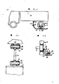
The example of apparatus of the present invention as shown in drawings.Fig. 1 represents to be arranged in the apparatus on the axle drive shaft wheel of diaxon vehicle, Fig. 2 represents to be installed in the apparatus on two axle drive shaft wheels of six-wheel vehicle, another tab sequencial of Fig. 3 presentation graphs 2, Fig. 4 represents to be installed in the stay bearing plate on the cylindrical pin, Fig. 5 is the stay bearing plate that is installed on the ball pin, Fig. 6 is the action of split journal bearing, and Fig. 7 has the mode of installing in the guide rail of bearing on stay bearing plate of ball pin, and Fig. 8 is the sketch of the apparatus do not installed on vehicle.Fig. 9,10,11 other examples of expression, wherein Fig. 9 represents to be installed in the view of the apparatus on the wheel of an axle drive shaft of diaxon vehicle, and Figure 10 be its lateral plan, and Figure 11 is the oscillating type installation of a carrier bar on the vehicle stay bearing plate.
A carrier 4 is arranged in the apparatus of the present invention, form by an installing component and a load bearing component.The installing component form is a flange 41.The load bearing component that is attached thereto, form are the arm 42 that pin 43 is arranged.Flange 41 is provided with hole 44, is used on wheel screw 9 fixing.A stay bearing plate 6 by being rigidly fixed in a bearing 5 on the stay bearing plate 6, rotatably is installed on the pin 43.
When this apparatus is installed in when using on the axle drive shaft 3, carrier 4 utilizes nut 10, and is eccentric fixing on wheel screw 9, and screw 9 was the spoke plate 1 fixing usefulness on axle drive shaft 3 of buying car in installments originally, and wheel screw 9 and carrier 4 are arranged in the outside of two wheel 2 disc 1.Stay bearing plate 6 relies on bearing 5 to be connected with the pin 43 of carrier 4.The axial location of bearing 5 and stay bearing plate 6 utilizes spring cotter 23 fixing on pin 43.Pin 43 is cylindrical.The horizontal axis distance of pin 43 horizontal axis and axle drive shaft 3 is very big, makes stay bearing plate 6 when extreme lower position, approximately and take turns 2 periphery on sustained height.When having rigid ground to replace in the low bearing capacity ground, pin 43 can suitably be selected one than the position near axle drive shaft 3 axis, in case stay bearing plate is being gone up clashing and breaking rigidly.If stay bearing plate 6 be arranged in the wheel periphery below, just automobile is more promptly freed.
When apparatus is used for two axle drive shafts 3,3 ' when going up, two axle drive shafts 3,3 ' two wheels, 2,2 ' common support plate 6, apparatus have in addition a carrier 4 '.Second carrier 4 ' be fixed on, second axle drive shaft 3 ' wheel 2 ' disc 1 ' on, bearing 11 rotatably, be installed in second carrier 4 ' pin 43 ' on.Slide in the slide rail 8 that bearing 11 can form on stay bearing plate 6.For eliminate wheel 2,2 ' vertical and horizontal rotate, adopted ball pin 43 '.Wheel 2,2 ' pendular suspension and pin 43,43 ' the pin 43,43 that causes of position, different angle ' axial distance change, can on stay bearing plate 6, be slidingly installed by bearing 11 and be eliminated.In order to guarantee to simplify erection work, be used to place ball pin 43,43 ' bearing 5,11 separated into two parts, promptly bottom 12 and 13, two parts of cap, 12,13 usefulness connecting pins 14 connect, and locate with spring cotter 15.
Can also carrier 4 ' pin 43 ' on roller 7 is installed, roller 7 contacts with stay bearing plate 6.Used be cylindrical pin 43 '.So the rolling of roller 7, can eliminate pin 43,43 ' axial distance change and wheel 2,2 ' laterally and vertically rotate.
If the part of vehicle is absorbed in low bearing capacity ground, carrier 4 is installed on the screw 9 of one or a few axle drive shaft 3, its dress is to carry out on the top of disc 1.The bearing 5 of band stay bearing plate 6 is placed on the pin 43 of carrier 4.Built on stilts during wheel 2 rotations supports on the ground up to the stay bearing plate that is arranged in wheel 2 sides.Stay bearing plate 6 lifts vehicle, moves onboard, is pressed onto on the ground up to the main portion pressure of wheel 2.If at this moment vehicle still can not rely on wheel 2 to advance, just continue rotation, repeat above-mentioned circulation, can rely on wheel 2 to advance up to vehicle.Then stay bearing plate 6 is shed.If depression also may continue, can be with carrier 4 to continue to go slowly.
If apparatus only is used on the axle drive shaft 3, pin 43 is cylindrical.Assurance has the guiding that is parallel to wheel 2 planes to supporting 6.In order to guarantee that stay bearing plate 6 can support on the ground smooth-goingly, bearing 5 should be arranged in the front of the center of gravity of stay bearing plate 6 by working direction.
When apparatus being used in many axle drive shafts 3,3 ' when going up, must carrier 4,4 ', by roughly the same angular distance be installed in wheel 2,2 ' disc 1,1 ' on.
Fig. 9,10,11 apparatus have a carrier 4, are formed by an installing component and a load bearing component.The installing component form is a flange 41, and load bearing component is formed by an arm 42 and a pin 43.For flange being installed on the wheel screw 9 flange porose 44.A stay bearing plate 6 is installed on the pin 43 by bearing 5, and bearing 5 is rigidly connected with stay bearing plate 6.A bearing 17 is rigidly connected to an end of stay bearing plate 6.The first pontes of a carrier bar 21 is installed on the bearing 17 with cylindrical pin 18, can swing.Second connecting bridge of carrier bar 21 is installed on the vehicle and swings.
When a vehicle part is absorbed in ground, carrier 4 and stay bearing plate 6, be placed on disc 1 outside of the two-wheeled 2 of axle drive shaft 3, be installed on the wheel screw 9 with nut 10.Second connecting bridge of carrier bar 21 is with bearing 17 on the vehicle 22 of pin 18 ' be installed in ' go up swing.The axial location of bearing 5 of band stay bearing plate 6 is determined by the spring cotter on the pin 43 23, carrier bar 21 and pin 18,18 ' axial location, by bearing 17,17 ' add spring cotter 24,24 ' determined.
If vehicle has left ground, wheel 2 continues rotation, up to the stay bearing plate 6 that is installed in wheel 2 sides, reaches and supports ground-surface position.Supported plate 6 liftings of vehicle are advanced in the above, can be pressed in its most of pressure on the ground up to wheel 2.This activity is carried out repeatedly, can advance with wheel 2 up to vehicle.Stay bearing plate 6 usefulness carrier bars 21 keep its level attitudes, therefore can prevent stuck on the ground or are absorbed in the ground.

Claims (5)

1、一种把轮载汽车从低承载力地面上解脱出的器械中,有一个支撑件,其上装有支撑在地面上的支撑表面,有装置用于将支撑件安装在驱动轴的驱动轮的辐板上,其特征在于借助于一根销把支撑件安装在驱动轴的驱动轮辐板的外侧上可以旋转,支撑表面与驱动轮轴有一个距离,使支撑表面的位置超出该驱动轮的滚动半径之外。1. A device for releasing a wheeled vehicle from a low-load-bearing ground, comprising a support member having a support surface mounted thereon for supporting the ground, and means for mounting the support member on a spoke of a drive wheel of a drive shaft, wherein the support member is rotatably mounted on the outer side of the spoke of the drive wheel of the drive shaft by means of a pin, and wherein the support surface is spaced apart from the drive wheel shaft so as to be positioned outside the rolling radius of the drive wheel. 2、根据权利要求第1项中之把轮载汽车从低承载力地面上脱出的器械,其特征为支撑件在另一个销上摆动并滑动,该另一个销刚性固定在另一驱动轴的另一驱动轮的辐板外侧。2. The device for removing a wheeled vehicle from a low-load-bearing ground according to claim 1, wherein the support member swings and slides on another pin which is rigidly fixed to the outer side of the web of the other driving wheel of the other driving shaft. 3、根据权利要求第1及2项中之把轮载汽车从低承载力地面上脱出的器械,其特征为支撑件通过一个承载器固定在驱动轮的辐板上,该承载器有两根臂,第一臂上设放该销,第二臂利用该驱动轴的紧固螺丝,刚性固定在驱动轮的该辐板上,支撑件通过另一有两根臂的承载器,固定在该另一个驱动轴的该另一个驱动轮辐板上,该另一个承载器的第一臂上设有该另一个销,第二臂用该另一个驱动轮的紧固螺丝,刚性固定在该另一个驱动轴的该另一车轮辐板上,其特征该另销安装在支撑件上,在车辆的纵向轴线上滑动。3. The device for removing a wheeled vehicle from a low-load-bearing ground according to claims 1 and 2, characterized in that the support member is fixed to the spoke of the driving wheel by a carrier, the carrier having two arms, the pin being provided on the first arm, and the second arm being rigidly fixed to the spoke of the driving wheel by means of the fastening screw of the driving shaft, the support member is fixed to the spoke of the other driving wheel of the other driving shaft by means of another carrier having two arms, the first arm of the other carrier being provided with the other pin, and the second arm being rigidly fixed to the spoke of the other wheel of the other driving shaft by means of the fastening screw of the other driving wheel, characterized in that the other pin is mounted on the support member and slides on the longitudinal axis of the vehicle. 4、根据权利要求第1项中之把轮载汽车从低承载力地面上脱出的器械,其特征为支撑件用一根有两根臂的杆和车辆连接,第一臂设有第一销安装在支撑件上旋转,第二臂设有第二销,在车辆上以可旋转的方式安装在该驱动轮的外侧。4. The device for removing a wheeled vehicle from a low-load-bearing surface according to claim 1, wherein the support member is connected to the vehicle by a rod having two arms, the first arm being provided with a first pin and being rotatably mounted on the support member, and the second arm being provided with a second pin and being rotatably mounted on the vehicle on the outer side of the driving wheel. 5、根据权利要求第1及4项中之把轮载汽车从承载力低的地面上脱出的器械,其特征为该第二销安装在车架上旋转。5. The device for removing a wheeled vehicle from a low-load-bearing ground according to claims 1 and 4, wherein the second pin is rotatably mounted on the vehicle frame.
CN86106930.7A 1985-10-22 1986-10-21 Low-load ground running device for wheel-mounted automobile Expired CN1004797B (en)

Applications Claiming Priority (4)

Application Number Priority Date Filing Date Title
CS857558A CS254457B1 (en) 1985-10-22 1985-10-22 A device for recovering a wheeled motor vehicle from poorly carrying terrain
CSPV7558-85 1985-10-22
CS861259A CS254843B1 (en) 1986-02-24 1986-02-24 Equipment for wheel motor vehicle breakdown from little bearing terrain
CSPV1259-86 1986-02-24

Publications (2)

Publication Number Publication Date
CN86106930A true CN86106930A (en) 1987-06-03
CN1004797B CN1004797B (en) 1989-07-19

Family

ID=25745407

Family Applications (1)

Application Number Title Priority Date Filing Date
CN86106930.7A Expired CN1004797B (en) 1985-10-22 1986-10-21 Low-load ground running device for wheel-mounted automobile

Country Status (4)

Country Link
CN (1) CN1004797B (en)
DE (1) DE3635769A1 (en)
FR (1) FR2592847B1 (en)
GB (1) GB2182006B (en)

Cited By (8)

* Cited by examiner, † Cited by third party
Publication number Priority date Publication date Assignee Title
CN105800498A (en) * 2016-05-30 2016-07-27 吴超 Hydraulic cross sliding rail rescue aid
CN105800507A (en) * 2016-05-30 2016-07-27 吴超 Rescue method of equipment for hand-operated cross slide rail rescue
CN105800499A (en) * 2016-05-30 2016-07-27 吴超 Rescue method of hand-operated cross slide rail rescue equipment
CN105800506A (en) * 2016-05-30 2016-07-27 吴超 Rescue method of a hand-operated cross slide rail rescue device
CN105923570A (en) * 2016-05-30 2016-09-07 吴超 A hand-cranked cross slide rail rescue device
CN105947929A (en) * 2016-05-30 2016-09-21 吴超 A hydraulic cross slide rail rescue equipment
WO2020177239A1 (en) * 2019-03-01 2020-09-10 庄勒 Existing power self-rescuing and traveling device and method for vehicle in soft and sinkable road conditions
CN112976966A (en) * 2021-03-19 2021-06-18 杭州威泊电子商务有限公司 Automobile tire falls off and sinks auxiliary device

Families Citing this family (2)

* Cited by examiner, † Cited by third party
Publication number Priority date Publication date Assignee Title
JP5584549B2 (en) * 2010-08-05 2014-09-03 株式会社Ihiエアロスペース vehicle
CN108099484B (en) * 2017-11-10 2019-12-10 国家电网公司 Electric power inspection vehicle for severe road conditions

Family Cites Families (9)

* Cited by examiner, † Cited by third party
Publication number Priority date Publication date Assignee Title
CH114341A (en) * 1925-06-17 1926-07-16 Gottlieb Tanner Wheel lifters for vehicles.
US2056116A (en) * 1935-02-20 1936-09-29 Gerald J Nash Automobile jack
US2146175A (en) * 1938-02-14 1939-02-07 Carl D Dillingham Traction wheel
US2411803A (en) * 1945-06-28 1946-11-26 Loretta Parrott Vehicle jack
US2503111A (en) * 1949-03-30 1950-04-04 Higgins Inc Amphibious vehicle
FR1052308A (en) * 1952-03-11 1954-01-22 Improvements to motor vehicles
US2777527A (en) * 1953-03-27 1957-01-15 Reginald Brian Omant Traction device for motor vehicles
DD35115A1 (en) * 1961-10-24 1965-01-25 Disk drive for construction machinery, excavators, conveyors, agricultural machinery and the like
FR1596674A (en) * 1968-11-15 1970-06-22

Cited By (11)

* Cited by examiner, † Cited by third party
Publication number Priority date Publication date Assignee Title
CN105800498A (en) * 2016-05-30 2016-07-27 吴超 Hydraulic cross sliding rail rescue aid
CN105800507A (en) * 2016-05-30 2016-07-27 吴超 Rescue method of equipment for hand-operated cross slide rail rescue
CN105800499A (en) * 2016-05-30 2016-07-27 吴超 Rescue method of hand-operated cross slide rail rescue equipment
CN105800506A (en) * 2016-05-30 2016-07-27 吴超 Rescue method of a hand-operated cross slide rail rescue device
CN105923570A (en) * 2016-05-30 2016-09-07 吴超 A hand-cranked cross slide rail rescue device
CN105947929A (en) * 2016-05-30 2016-09-21 吴超 A hydraulic cross slide rail rescue equipment
CN105947929B (en) * 2016-05-30 2018-01-16 衢州市易凡设计有限公司 A hydraulic cross slide rail rescue equipment
CN107879285A (en) * 2016-05-30 2018-04-06 衢州市易凡设计有限公司 A kind of method of suing and labouring of the deliverance apparatus of hand-rail type cross slide rail self-locking
WO2020177239A1 (en) * 2019-03-01 2020-09-10 庄勒 Existing power self-rescuing and traveling device and method for vehicle in soft and sinkable road conditions
CN112976966A (en) * 2021-03-19 2021-06-18 杭州威泊电子商务有限公司 Automobile tire falls off and sinks auxiliary device
CN112976966B (en) * 2021-03-19 2023-01-20 山东省三利轮胎制造有限公司 Automobile tire falls off and sinks auxiliary device

Also Published As

Publication number Publication date
FR2592847A1 (en) 1987-07-17
DE3635769A1 (en) 1987-04-23
GB2182006B (en) 1988-12-14
CN1004797B (en) 1989-07-19
DE3635769C2 (en) 1990-07-05
FR2592847B1 (en) 1992-08-07
GB2182006A (en) 1987-05-07
GB8625081D0 (en) 1986-11-26

Similar Documents

Publication Publication Date Title
CN86106930A (en) Device for releasing wheel motor vehicle
CN106945467B (en) Vehicle walking driving direction navigation mechanism
EP0245220B1 (en) A suspension for motored and unmotored wheels of vehicles
JP2003517969A (en) Steering knuckle
KR890001990B1 (en) Bogie
KR100381342B1 (en) Bottom contact type third rail shoe gear for light rail transit
CN101327887A (en) Drive for vertical lifts
JPS6127801Y2 (en)
US20200331525A1 (en) Roll induced four wheel steering vehicle
CN207028744U (en) For running gear hitch and there is its walking robot
US3042133A (en) Independent wheel suspension
JPH09207768A (en) Truck support structure for single rail carrying machine
CN213386326U (en) Traveling mechanism of rail transport machine
SU1712229A1 (en) Semitrailer
CN115257850B (en) De-icing shoe units, bogies and rolling stock
JP3754203B2 (en) Track traveling device
KR100264605B1 (en) Stabilizer Bar Link Assembly
CN106978923B (en) Vertical parking garage
JPH0535168Y2 (en)
CN223644762U (en) Multifunctional railway vehicle
JP3600677B2 (en) Body moving device and body moving device for track work vehicle
CN223999522U (en) Transport vechicle convenient to turn
JP4942648B2 (en) Automotive wheel support equipment
CN214648670U (en) AGV dolly
CN2688347Y (en) Travelling wheel of mechanical ride

Legal Events

Date Code Title Description
C06 Publication
PB01 Publication
C10 Entry into substantive examination
SE01 Entry into force of request for substantive examination
C13 Decision
GR02 Examined patent application
C14 Grant of patent or utility model
GR01 Patent grant
C19 Lapse of patent right due to non-payment of the annual fee
CF01 Termination of patent right due to non-payment of annual fee