DE102006053473B4 - Arrangement of a position sensor on a shaft of a drivable cylinder in a processing machine - Google Patents
Arrangement of a position sensor on a shaft of a drivable cylinder in a processing machine Download PDFInfo
- Publication number
- DE102006053473B4 DE102006053473B4 DE200610053473 DE102006053473A DE102006053473B4 DE 102006053473 B4 DE102006053473 B4 DE 102006053473B4 DE 200610053473 DE200610053473 DE 200610053473 DE 102006053473 A DE102006053473 A DE 102006053473A DE 102006053473 B4 DE102006053473 B4 DE 102006053473B4
- Authority
- DE
- Germany
- Prior art keywords
- cylinder
- shaft
- transmission element
- arrangement according
- position sensor
- Prior art date
- Legal status (The legal status is an assumption and is not a legal conclusion. Google has not performed a legal analysis and makes no representation as to the accuracy of the status listed.)
- Active
Links
- 238000007639 printing Methods 0.000 claims abstract description 7
- 230000005540 biological transmission Effects 0.000 claims description 23
- 238000007645 offset printing Methods 0.000 description 9
- 230000001360 synchronised effect Effects 0.000 description 3
- 238000012937 correction Methods 0.000 description 2
- 238000001514 detection method Methods 0.000 description 2
- 238000011161 development Methods 0.000 description 2
- 230000018109 developmental process Effects 0.000 description 2
- 239000000463 material Substances 0.000 description 2
- 239000011248 coating agent Substances 0.000 description 1
- 238000000576 coating method Methods 0.000 description 1
- 230000008878 coupling Effects 0.000 description 1
- 238000010168 coupling process Methods 0.000 description 1
- 238000005859 coupling reaction Methods 0.000 description 1
- 230000001419 dependent effect Effects 0.000 description 1
- 238000005516 engineering process Methods 0.000 description 1
- 239000004744 fabric Substances 0.000 description 1
- 238000010422 painting Methods 0.000 description 1
- 238000005096 rolling process Methods 0.000 description 1
- 239000000758 substrate Substances 0.000 description 1
Classifications
-
- G—PHYSICS
- G01—MEASURING; TESTING
- G01B—MEASURING LENGTH, THICKNESS OR SIMILAR LINEAR DIMENSIONS; MEASURING ANGLES; MEASURING AREAS; MEASURING IRREGULARITIES OF SURFACES OR CONTOURS
- G01B21/00—Measuring arrangements or details thereof, where the measuring technique is not covered by the other groups of this subclass, unspecified or not relevant
- G01B21/22—Measuring arrangements or details thereof, where the measuring technique is not covered by the other groups of this subclass, unspecified or not relevant for measuring angles or tapers; for testing the alignment of axes
-
- B—PERFORMING OPERATIONS; TRANSPORTING
- B41—PRINTING; LINING MACHINES; TYPEWRITERS; STAMPS
- B41F—PRINTING MACHINES OR PRESSES
- B41F13/00—Common details of rotary presses or machines
- B41F13/004—Electric or hydraulic features of drives
- B41F13/0045—Electric driving devices
-
- B—PERFORMING OPERATIONS; TRANSPORTING
- B41—PRINTING; LINING MACHINES; TYPEWRITERS; STAMPS
- B41F—PRINTING MACHINES OR PRESSES
- B41F33/00—Indicating, counting, warning, control or safety devices
- B41F33/04—Tripping devices or stop-motions
- B41F33/14—Automatic control of tripping devices by feelers, photoelectric devices, pneumatic devices, or other detectors
Landscapes
- Engineering & Computer Science (AREA)
- Mechanical Engineering (AREA)
- Physics & Mathematics (AREA)
- General Physics & Mathematics (AREA)
- Inking, Control Or Cleaning Of Printing Machines (AREA)
Abstract
Druckmaschine mit einem auf einer Welle eines antreibbaren Zylinders (2) angeordneten Lagegeber (7), der mit einer Drehmomentstütze (13, 14), welche am Seitengestell (15) und am Gebergehäuse (24) des Lagegebers (7) angeordnet ist, gekoppelt ist, wobei innerhalb des Gebergehäuses (24) ein verdrehfester Stator angeordnet ist innerhalb dessen ein als Hohlwelle ausgebildeter Rotor auf der Zylinderwelle fixiert ist,
dadurch gekennzeichnet,
dass der Zylinder (2) eine lageveränderbare Zylinderachse (11) aufweist,
dass die Drehmomentstütze (13, 14) an einer auf dem Zylinder (2) angeordneten Lagerung (18, 19) fixiert ist und das Gebergehäuse (24) des Lagegebers (7) mit der Lagerung (18, 19) verbunden ist.Printing machine with a on a shaft of a drivable cylinder (2) arranged position sensor (7) which is coupled to a torque arm (13, 14) which on the side frame (15) and the encoder housing (24) of the position sensor (7) is arranged wherein within the transmitter housing (24) a torsion-resistant stator is arranged within which a rotor designed as a hollow shaft is fixed on the cylinder shaft,
characterized,
the cylinder (2) has a position-adjustable cylinder axis (11),
the torque support (13, 14) is fixed to a bearing (18, 19) arranged on the cylinder (2) and the transmitter housing (24) of the position sensor (7) is connected to the bearing (18, 19).
Description
Die Erfindung betrifft eine Anordnung eines Lagegebers auf einer Welle eines antreibbaren Zylinders in einer Verarbeitungsmaschine nach dem Oberbegriff von Anspruch 1. Die Anordnung eignet sich insbesondere für eine Offsetdruckmaschine mit oder ohne Lackwerken bzw. eine Lackiermaschine bei denen ein Zylinder mit einem Einzelantrieb antreibbar ist.The The invention relates to an arrangement of a position sensor on a shaft of a drivable cylinder in a processing machine The preamble of claim 1. The arrangement is particularly suitable for one Offset printing machine with or without coating units or a painting machine at where a cylinder with a single drive is driven.
Ein
Lagegeber dieser Art ist aus
Weiterhin
ist aus
Aus
Gemäß
Der Erfindung liegt die Aufgabe zu Grunde, eine Druckmaschine der eingangs beschriebenen Art derart weiterzubilden, dass auf den Lagegeber störende Einflüsse zumindest spürbar reduziert werden und die Signalerfassung des Lagegebers mit höherer Genauigkeit erfolgt.Of the Invention is based on the object, a printing machine of the beginning further develop such a way that on the position encoder disturbing influences at least noticeable be reduced and the signal detection of the position encoder with higher accuracy he follows.
Gelöst wird die Aufgabe durch die Ausbildungsmerkmale von Anspruch 1. Weiterbildungen ergeben sich aus den abhängigen Ansprüchen.Is solved the task by the training features of claim 1. Further developments arise from the dependent ones Claims.
Ein erster Vorteil ist darin begründet, dass bei einem Zylinder mit veränderbarer Achsposition, beispielsweise einem Gummituchzylinder eines Offsetdruckwerkes, der zugeordnete Platten-/Formzylinder (Zylinder mit fester Achsposition) im Offsetdruckwerk mit einem Direktantrieb (Einzelantrieb) lagegeregelt antreibbar ist, indem ein verbesserter synchroner Winkellauf, insbesondere bei einem Platten-/Formzylinder mit einem Einzelantrieb, zwischen beiden Zylinder erzielbar ist.One the first advantage is that that with a cylinder with changeable Axial position, for example a blanket cylinder of an offset printing unit, the assigned plate / forme cylinder (cylinder with fixed axis position) in the offset printing unit with a direct drive (single drive) position-controlled is drivable by an improved synchronous angle run, in particular in a plate / form cylinder with a single drive, between the two cylinders is achievable.
Als zweiter Vorteil ist aufzuführen, dass der Sollwert für die Platten-/Formzylinderposition vom zugehörigen Gummituchzylinder (im Offsetdruckwerk) mit Hilfe je eines Lagegebers, insbesondere eines Drehwinkelgebers, abgenommen wird. Die Signale werden einer vorzugsweise zentralen Steuerung zugeführt, welche den jeweiligen Einzelantrieb des Platten-/Formzylinders dementsprechend ansteuert, so dass unabhängig von der Zylinderposition stets ein synchroner Winkellauf zwischen einem Zylinder mit fester Achsposition und einem Zylinder mit veränderbarer Achsposition gewährleistet ist.When second advantage is to list that the setpoint for the plate / form cylinder position from the associated Blanket cylinder (in offset printing unit) with the aid of one position sensor each, in particular a rotary encoder, is removed. The signals are fed to a preferably central controller, which the respective individual drive of the plate / forme cylinder accordingly controls, so that independent from the cylinder position always a synchronous angle between a cylinder with fixed axle position and a cylinder with changeable Axial position guaranteed is.
Ein dritter Vorteil ist darin begründet, dass störende, auf den Lagegeber wirkende Einflüsse, beispielsweise Schwingungen oder Taumelbewegungen, spürbar reduziert bzw. eliminiert werden. Die Signalerfassung des Lagegebers ist mit höherer Genauigkeit realisierbar.One the third advantage is that that disturbing, on the positioner acting influences, for example Vibrations or tumbling movements, noticeably reduced or eliminated become. The signal detection of the position sensor is with higher accuracy realizable.
Die Erfindung soll an einem Ausführungsbeispiel näher erläutert werden. Dabei zeigen schematisch:The Invention is intended to an embodiment be explained in more detail. Here are shown schematically:
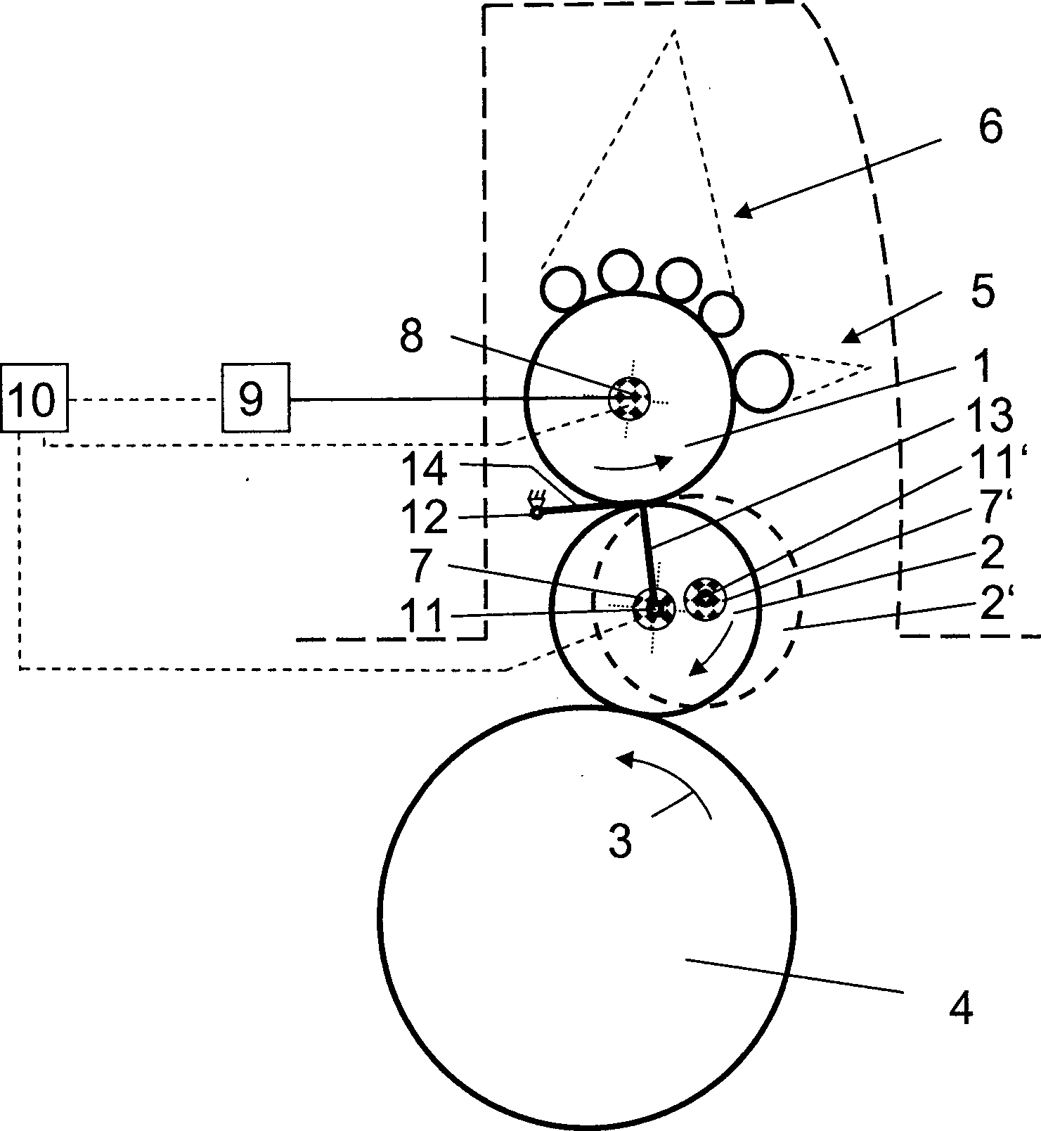
Gemäß
Der
Platten-/Formzylinder
Der
zweite Lagegeber
Auf
der lageveränderbaren
Zylinderachse
In
der vorliegenden Ausbildung ist der erste Lagegeber
Der
erste Lagegeber
Bevorzugt
ist das zweite Getriebeelement
Zwischen
dem ersten Lagegeber
Die
Drehmomentstütze
- 11
- Zylinder (Platten-/Formzylinder)cylinder (Plate / form cylinder)
- 22
- Zylinder (Gummituchzylinder)cylinder (Blanket cylinder)
- 33
- Förderrichtungconveying direction
- 44
- Druckzylinderpressure cylinder
- 55
- Feuchtwerkdampening
- 66
- Farbwerkinking
- 77
- erster Lagegeberfirst position encoder
- 88th
- zweiter Lagegebersecond position encoder
- 99
- Einzelantriebindividual drive
- 1010
- Maschinensteuerungmachine control
- 1111
- lageveränderbare Zylinderachserepositionable cylinder axis
- 1212
- gestellfestes Drehgelenkframe fixed swivel
- 1313
- Drehmomentstütze (erstes Getriebeelement)Torque arm (first Transmission member)
- 1414
- Drehmomentstütze (zweites Getriebeelement)Torque arm (second Transmission member)
- 1515
- Seitengestellside frame
- 1616
- Antriebsraddrive wheel
- 1717
- Berührzonecontact zone
- 1818
- Radiallagerradial bearings
- 1919
- Lagerbockbearing block
- 2020
- Halterungbracket
- 2121
- Zapfenspigot
- 2222
- Drehgelenkswivel
- 2323
- Eintriebinput drive
- 2424
- Gebergehäuseencoder housing
Claims (7)
Priority Applications (1)
| Application Number | Priority Date | Filing Date | Title |
|---|---|---|---|
| DE200610053473 DE102006053473B4 (en) | 2006-11-14 | 2006-11-14 | Arrangement of a position sensor on a shaft of a drivable cylinder in a processing machine |
Applications Claiming Priority (1)
| Application Number | Priority Date | Filing Date | Title |
|---|---|---|---|
| DE200610053473 DE102006053473B4 (en) | 2006-11-14 | 2006-11-14 | Arrangement of a position sensor on a shaft of a drivable cylinder in a processing machine |
Publications (2)
| Publication Number | Publication Date |
|---|---|
| DE102006053473A1 DE102006053473A1 (en) | 2008-05-15 |
| DE102006053473B4 true DE102006053473B4 (en) | 2009-12-10 |
Family
ID=39277671
Family Applications (1)
| Application Number | Title | Priority Date | Filing Date |
|---|---|---|---|
| DE200610053473 Active DE102006053473B4 (en) | 2006-11-14 | 2006-11-14 | Arrangement of a position sensor on a shaft of a drivable cylinder in a processing machine |
Country Status (1)
| Country | Link |
|---|---|
| DE (1) | DE102006053473B4 (en) |
Families Citing this family (1)
| Publication number | Priority date | Publication date | Assignee | Title |
|---|---|---|---|---|
| DE102022102028A1 (en) | 2022-01-28 | 2023-08-03 | Koenig & Bauer Ag | Processing unit and method for operating a processing unit of a processing machine |
Citations (4)
| Publication number | Priority date | Publication date | Assignee | Title |
|---|---|---|---|---|
| DE8535561U1 (en) * | 1985-12-18 | 1992-06-04 | Heidelberger Druckmaschinen Ag, 6900 Heidelberg | Tachogenerator |
| EP0812683A1 (en) * | 1996-06-11 | 1997-12-17 | MAN Roland Druckmaschinen AG | Drive for a printing press |
| DE19904471A1 (en) * | 1999-02-04 | 2000-08-10 | Heidenhain Gmbh Dr Johannes | Shaft encoder clamping device for connection with rotor of shaft encoder to measure relative orientation of tool during machining of work piece |
| EP1593510A2 (en) * | 2004-05-05 | 2005-11-09 | MAN Roland Druckmaschinen AG | Position indicator for a direct driven cylinder in a processing machine |
-
2006
- 2006-11-14 DE DE200610053473 patent/DE102006053473B4/en active Active
Patent Citations (4)
| Publication number | Priority date | Publication date | Assignee | Title |
|---|---|---|---|---|
| DE8535561U1 (en) * | 1985-12-18 | 1992-06-04 | Heidelberger Druckmaschinen Ag, 6900 Heidelberg | Tachogenerator |
| EP0812683A1 (en) * | 1996-06-11 | 1997-12-17 | MAN Roland Druckmaschinen AG | Drive for a printing press |
| DE19904471A1 (en) * | 1999-02-04 | 2000-08-10 | Heidenhain Gmbh Dr Johannes | Shaft encoder clamping device for connection with rotor of shaft encoder to measure relative orientation of tool during machining of work piece |
| EP1593510A2 (en) * | 2004-05-05 | 2005-11-09 | MAN Roland Druckmaschinen AG | Position indicator for a direct driven cylinder in a processing machine |
Also Published As
| Publication number | Publication date |
|---|---|
| DE102006053473A1 (en) | 2008-05-15 |
Similar Documents
| Publication | Publication Date | Title |
|---|---|---|
| EP0813959B1 (en) | Driven cylinder | |
| WO2001087605A1 (en) | Driving member for rotating component integral with a printing machine and method for separating said driving member | |
| DE102006053473B4 (en) | Arrangement of a position sensor on a shaft of a drivable cylinder in a processing machine | |
| EP1431034B1 (en) | Position adjusting device for rotary body with direct drive | |
| EP1872944B9 (en) | Method and device for powering printing plate cylinders | |
| DE102005018528B4 (en) | Position transmitter for a direct drive of a cylinder in a processing machine | |
| EP1742795B1 (en) | Direct drive for a cylinder of a converting machine | |
| DE102005018677A1 (en) | Drive for a printing machine or lacquering machine comprises a common geared traction mechanism having a freely rotating drive wheel arranged on each plate cylinder and/or printing cylinder | |
| EP2067619B1 (en) | Method and drive for driving a sheet material processing machine | |
| EP2114681B1 (en) | Printing unit of a rotary printing press and a method for washing a dampening unit of a printing unit | |
| DE102012207123A1 (en) | Sheet-fed offset rotary printing machine, has elastic coupling element arranged between stator and machine frame and for allowing radial deflection of amount of position change of plate cylinder that is supported in machine frame | |
| EP1439060B1 (en) | Register adjusting device for sheet transfert drum of a sheet-fed press | |
| DE102005029969A1 (en) | Arrangement of angle e.g. for rotation drives, has two drives for revolution of two wheels with revolution in first mode of operation have given relative angle of rotation | |
| EP1923213B1 (en) | Printing unit of a printing press with two double printing groups arranged over each other | |
| EP1433600B1 (en) | Register adjusting device for sheet transfert drum of a sheet-fed press | |
| DE102022102028A1 (en) | Processing unit and method for operating a processing unit of a processing machine | |
| DE4139326C2 (en) | Device for setting the circumferential register on rotary printing presses | |
| EP1964676A2 (en) | Assembly of a rotation angle measuring device for a powered cylinder in a processing machine and method for measuring rotation angles | |
| EP1433601B1 (en) | Register adjusting device for sheet transfert drum of a sheet-fed press | |
| DE102017204515B4 (en) | Method for operating a sheet-processing machine | |
| DE10260759A1 (en) | Sheet-fed printing press has format change unit with non-rotating spindle with outer teeth at a fixed distance from the drum | |
| DE102015118911A1 (en) | Drive for sheet-fed rotary printing machines | |
| WO2009121717A1 (en) | Rotary printing press which processes printing material | |
| DE10106412A1 (en) | For the direct working of the printing surface of a form or cylinder at the printing press a mechanism disengages the drum drive shaft so that the press drives and transmissions are not used to reduce wear | |
| DE102005019512A1 (en) | Offset printing device for rotary printing press has at least one ink application roll drive with synchronous axial changing relative to adjacent ink rubbing rolls |
Legal Events
| Date | Code | Title | Description |
|---|---|---|---|
| OP8 | Request for examination as to paragraph 44 patent law | ||
| 8127 | New person/name/address of the applicant |
Owner name: MANROLAND AG, 63075 OFFENBACH, DE |
|
| 8364 | No opposition during term of opposition | ||
| R081 | Change of applicant/patentee |
Owner name: MANROLAND SHEETFED GMBH, DE Free format text: FORMER OWNER: MANROLAND AG, 63075 OFFENBACH, DE Effective date: 20120510 |