DE102011108564A1 - Single-stage distributor for an injection molding device - Google Patents
Single-stage distributor for an injection molding device Download PDFInfo
- Publication number
- DE102011108564A1 DE102011108564A1 DE102011108564A DE102011108564A DE102011108564A1 DE 102011108564 A1 DE102011108564 A1 DE 102011108564A1 DE 102011108564 A DE102011108564 A DE 102011108564A DE 102011108564 A DE102011108564 A DE 102011108564A DE 102011108564 A1 DE102011108564 A1 DE 102011108564A1
- Authority
- DE
- Germany
- Prior art keywords
- melt
- channels
- splitter
- downstream
- channel
- Prior art date
- Legal status (The legal status is an assumption and is not a legal conclusion. Google has not performed a legal analysis and makes no representation as to the accuracy of the status listed.)
- Ceased
Links
- 238000001746 injection moulding Methods 0.000 title claims abstract description 30
- 239000000155 melt Substances 0.000 claims abstract description 124
- 238000011144 upstream manufacturing Methods 0.000 claims abstract description 36
- 239000012530 fluid Substances 0.000 claims description 7
- 239000000463 material Substances 0.000 claims description 7
- 238000004891 communication Methods 0.000 claims description 5
- 229910001315 Tool steel Inorganic materials 0.000 claims description 4
- 206010041662 Splinter Diseases 0.000 description 16
- 230000004927 fusion Effects 0.000 description 13
- 239000000289 melt material Substances 0.000 description 9
- 238000009826 distribution Methods 0.000 description 8
- 238000004519 manufacturing process Methods 0.000 description 4
- 239000012634 fragment Substances 0.000 description 3
- 238000003754 machining Methods 0.000 description 2
- 238000000034 method Methods 0.000 description 2
- 239000012778 molding material Substances 0.000 description 2
- 239000007787 solid Substances 0.000 description 2
- RYGMFSIKBFXOCR-UHFFFAOYSA-N Copper Chemical compound [Cu] RYGMFSIKBFXOCR-UHFFFAOYSA-N 0.000 description 1
- 229910000881 Cu alloy Inorganic materials 0.000 description 1
- 229910000831 Steel Inorganic materials 0.000 description 1
- 230000001154 acute effect Effects 0.000 description 1
- 238000000149 argon plasma sintering Methods 0.000 description 1
- 230000000712 assembly Effects 0.000 description 1
- 238000000429 assembly Methods 0.000 description 1
- 230000015572 biosynthetic process Effects 0.000 description 1
- 238000005219 brazing Methods 0.000 description 1
- 238000004140 cleaning Methods 0.000 description 1
- 239000004020 conductor Substances 0.000 description 1
- 229910052802 copper Inorganic materials 0.000 description 1
- 239000010949 copper Substances 0.000 description 1
- 238000011161 development Methods 0.000 description 1
- 238000005755 formation reaction Methods 0.000 description 1
- 238000010438 heat treatment Methods 0.000 description 1
- 238000002347 injection Methods 0.000 description 1
- 239000007924 injection Substances 0.000 description 1
- 238000012423 maintenance Methods 0.000 description 1
- 238000002844 melting Methods 0.000 description 1
- 230000008018 melting Effects 0.000 description 1
- 239000002184 metal Substances 0.000 description 1
- 229910052751 metal Inorganic materials 0.000 description 1
- 238000012544 monitoring process Methods 0.000 description 1
- 230000037361 pathway Effects 0.000 description 1
- 229910000679 solder Inorganic materials 0.000 description 1
- 239000011343 solid material Substances 0.000 description 1
- 239000010959 steel Substances 0.000 description 1
- 238000012546 transfer Methods 0.000 description 1
- 238000003466 welding Methods 0.000 description 1
Images


Classifications
-
- B—PERFORMING OPERATIONS; TRANSPORTING
- B29—WORKING OF PLASTICS; WORKING OF SUBSTANCES IN A PLASTIC STATE IN GENERAL
- B29C—SHAPING OR JOINING OF PLASTICS; SHAPING OF MATERIAL IN A PLASTIC STATE, NOT OTHERWISE PROVIDED FOR; AFTER-TREATMENT OF THE SHAPED PRODUCTS, e.g. REPAIRING
- B29C45/00—Injection moulding, i.e. forcing the required volume of moulding material through a nozzle into a closed mould; Apparatus therefor
- B29C45/17—Component parts, details or accessories; Auxiliary operations
- B29C45/26—Moulds
- B29C45/27—Sprue channels ; Runner channels or runner nozzles
- B29C45/2725—Manifolds
-
- B—PERFORMING OPERATIONS; TRANSPORTING
- B29—WORKING OF PLASTICS; WORKING OF SUBSTANCES IN A PLASTIC STATE IN GENERAL
- B29C—SHAPING OR JOINING OF PLASTICS; SHAPING OF MATERIAL IN A PLASTIC STATE, NOT OTHERWISE PROVIDED FOR; AFTER-TREATMENT OF THE SHAPED PRODUCTS, e.g. REPAIRING
- B29C45/00—Injection moulding, i.e. forcing the required volume of moulding material through a nozzle into a closed mould; Apparatus therefor
- B29C45/17—Component parts, details or accessories; Auxiliary operations
- B29C45/26—Moulds
- B29C45/27—Sprue channels ; Runner channels or runner nozzles
- B29C45/2701—Details not specific to hot or cold runner channels
- B29C45/2703—Means for controlling the runner flow, e.g. runner switches, adjustable runners or gates
-
- B—PERFORMING OPERATIONS; TRANSPORTING
- B29—WORKING OF PLASTICS; WORKING OF SUBSTANCES IN A PLASTIC STATE IN GENERAL
- B29C—SHAPING OR JOINING OF PLASTICS; SHAPING OF MATERIAL IN A PLASTIC STATE, NOT OTHERWISE PROVIDED FOR; AFTER-TREATMENT OF THE SHAPED PRODUCTS, e.g. REPAIRING
- B29C45/00—Injection moulding, i.e. forcing the required volume of moulding material through a nozzle into a closed mould; Apparatus therefor
- B29C45/17—Component parts, details or accessories; Auxiliary operations
- B29C45/26—Moulds
- B29C45/27—Sprue channels ; Runner channels or runner nozzles
- B29C45/2725—Manifolds
- B29C2045/2733—Inserts, plugs, bushings
Landscapes
- Engineering & Computer Science (AREA)
- Manufacturing & Machinery (AREA)
- Mechanical Engineering (AREA)
- Moulds For Moulding Plastics Or The Like (AREA)
- Injection Moulding Of Plastics Or The Like (AREA)
Abstract
Es wird eine Spritzgießvorrichtung offenbart mit einem einstufigen Verteiler, der einen Schmelzesplitter verwendet. Der Verteiler definiert einen Einlass und eine Vielzahl von Auslässen mit mindestens einem stromaufwärtigen Schmelzekanal und einer Vielzahl von stromabwärtigen Schmelzekanälen, die zwischen dem Einlass und der Vielzahl von Auslässen angeordnet sind. Der stromaufwärtige Schmelzekanal verzweigt sich in die Vielzahl von stromabwärtigen Schmelzekanälen, wobei der stromaufwärtige Schmelzekanal und jeder der stromabwärtigen Schmelzekanäle sich in Längsrichtung in der gleichen Ebene erstrecken. Der Schmelzesplitter ist zumindest teilweise in dem stromaufwärtigen Schmelzekanal positioniert, wo der stromaufwärtige Schmelzekanal sich m überschneidet. Der Schmelzesplitter teilt einen von dem stromaufwärtigen Schmelzekanal erhaltenen Schmelzestrom in im Wesentlichen gleiche Volumina auf und führt dann jedes der im Wesentlichen gleichen Volumina in einen entsprechenden der Vielzahl von stromabwärtigen Schmelzekanälen.An injection molding apparatus is disclosed having a single stage manifold using a melt splitter. The manifold defines an inlet and a plurality of outlets having at least one upstream melt channel and a plurality of downstream melt channels disposed between the inlet and the plurality of outlets. The upstream melt channel branches into the plurality of downstream melt channels, with the upstream melt channel and each of the downstream melt channels extending longitudinally in the same plane. The melt splitter is at least partially positioned in the upstream melt channel where the upstream melt channel intersects m. The melt splitter divides a melt stream obtained from the upstream melt channel into substantially equal volumes and then leads each of the substantially equal volumes into a corresponding one of the plurality of downstream melt channels.
Description
GEBIET DER ERFINDUNGFIELD OF THE INVENTION
Die vorliegende Erfindung bezieht sich im Allgemeinen auf eine Spritzgießvorrichtung und im Besonderen auf einen Verteiler zum Führen einer Schmelzeströmung durch die Spritzgießvorrichtung.The present invention relates generally to an injection molding apparatus, and more particularly to a manifold for guiding melt flow through the injection molding apparatus.
HINTERGRUND DER ERFINDUNGBACKGROUND OF THE INVENTION
Die Verwendung von Verteilern in Spritzgießsystemen um eine Schmelzeströmung von einer Schmelzequelle an eine oder mehrere Düsen zu übertragen und so die Schmelze an einen oder mehrere Formhohlräume zu fördern ist gut bekannt. Weiterhin ist es gut bekannt, dass es in vielen Spritzgießanwendungen wichtig ist, dass das Layout des Verteilerschmelzekanals oder das Läufersystem, wie es in der Technik bekannt ist, so erstellt ist, dass jeder Hohlraum eine Strömung von Schmelze erhält, die die gleiche Temperatur und die gleiche Scherungsentwicklung aufweist. Solche Systeme kann man als ”balanciert” beschreiben. Das Ausbalancieren von Läufersystemen von Verteilern ist wichtig, um eine bessere Konsistenz oder Homogenität des Schmelzestroms zu erreichen, wenn er von einem einzelnen Schmelzestrom an dem Verteilereinlass zu einer Vielzahl von Verteilerauslässen, die einer Vielzahl von Formhohlräumen in einer Mehrfachhohlraum-Anwendung entsprechen, aufgeteilt wird. Das Resultat des Ausbalancierens des Schmelzestroms ist ein insgesamter Anstieg der Qualität und der Einheitlichkeit der spritzgegossenen Formteile, im Vergleich mit Teilen, die in Systemen ausgeformt wurden, die nicht in solcher Weise ausbalanciert sind.The use of manifolds in injection molding systems to transfer a melt stream from a melt source to one or more nozzles and thus convey the melt to one or more mold cavities is well known. Furthermore, it is well known that in many injection molding applications, it is important that the layout of the manifold melt channel or rotor system, as known in the art, be constructed so that each cavity receives a flow of melt having the same temperature and temperature has the same shear development. Such systems can be described as "balanced". Balancing runner systems of manifolds is important to achieve better consistency or homogeneity of the melt stream when it is split from a single melt stream at the manifold inlet to a plurality of manifold outlets corresponding to a plurality of mold cavities in a multi-cavity application. The result of balancing the melt stream is an overall increase in the quality and consistency of the injection molded parts as compared to parts formed in systems that are not so balanced.
Das herkömmliche Ausbalancieren des Schmelzestroms umfasst das Ausbilden des Verteilers mit geometrisch passenden Layouts der Läufer; d. h.: passende Durchmesser, gleiche Läuferlängen, Anzahl von Umlenkungen und Wechsel von Schmelzekanalstufen in jedem Schmelzeweg von dem Verteilereinlass zu einem entsprechenden Formhohlraum. Jedoch kann manchmal, trotz eines passenden Läuferlayouts, der Schmelzestrom von Hohlraum zu Hohlraum unterschiedlich sein, wegen der Scherung, die den Schmelzestrom aufheizt, wenn er entlang des Schmelzewegs durch die Läufer gedrückt wird. Im Besonderen, wenn der Schmelzestrom unter Druck durch eine Bohrung gedrückt wird, d. h. durch einen Läufer oder Verteilerschmelzekanal wie in einem Heißläuferverteiler gefertigt, wird der Schmelzestrom in dem Bereich angrenzend an die Bohrung oder der Schmelzekanalwand einer Scherung ausgesetzt mit einer entsprechenden lokalen Anhebung der Temperatur. Die Folge ist eine Temperaturdifferenz quer über die Bohrung oder den Schmelzekanal, wobei die Mitte des Schmelzestroms kälter ist als das Schmelzmaterial näher an der Bohrung oder der Schmelzekanalrand. Dieses Phänomen wiederholt sich an jeder Aufteilung und/oder Umlenkung des Schmelzestroms entlang des Schmelzewegs und kann zu einer Unausgewogenheit des mittels Scherung aufgeheizten Materials zwischen den Läufern und anschließend zwischen den Hohlräumen der Spritzgießvorrichtung führen.Conventional melt stream balancing involves forming the manifold with geometrically matching layouts of the runners; d. h.: Suitable diameters, same rotor lengths, number of deflections and change of Schmelzenkanalstufen in each melt path from the distributor inlet to a corresponding mold cavity. However, sometimes, despite a suitable rotor layout, the melt flow may vary from cavity to cavity because of the shear that heats the melt stream as it is pushed along the melt path by the runners. In particular, when the melt stream is forced under pressure through a bore, i. H. through a runner or manifold melted channel, as in a hot runner manifold, the melt stream is sheared in the region adjacent the bore or melt channel wall with a corresponding local increase in temperature. The result is a temperature differential across the bore or melt channel, with the center of the melt stream being colder than the melt material closer to the bore or melt channel edge. This phenomenon is repeated at each split and / or redirection of the melt stream along the melt path and may result in an imbalance of the material heated by shear between the runners and subsequently between the cavities of the injection molding apparatus.
Obwohl eine Vielfalt von Einrichtungen und Verfahren existieren oder vorgeschlagen wurden, die sich mit der Notwendigkeit des Ausbalancierens zwischen den an die Hohlräume eines Heißläufer-Spritzgießsystems gelieferten Schmelze umfassen, besteht weiterhin die Notwendigkeit, die Eigenschaften eines durch einen Heißläuferverteiler strömenden Schmelzestroms von formbarem Material auszubalancieren oder zu verbessern, so dass jeder Hohlraum eines Systems eine verhältnismäßig konsistente oder homogene Schmelze erhält, um dadurch in ihrer Teilekonsistenz verbesserte Teile herzustellen.Although a variety of devices and methods exist or have been proposed that involve the need to balance the melt delivered to the cavities of a hot runner injection molding system, there continues to be a need to balance the properties of a melt stream of moldable material flowing through a hot runner manifold so that each cavity of a system receives a relatively consistent or homogeneous melt to thereby produce improved parts in their part consistency.
KURZER ÜBERBLICK ÜBER DIE ERFINDUNGBRIEF SUMMARY OF THE INVENTION
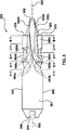
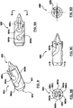
Ausführungsformen der Erfindung sind auf eine Spritzgießvorrichtung gerichtet, die einen einstufigen Verteiler mit einem Schmelzeabzweig umfassen. Der Verteiler erhält einen Schmelzestrom von formbarem Material von einer Schmelzequelle und führt den Schmelzestrom zu dessen Auslässen. Der Verteiler umfasst einen stromaufwärtigen Schmelzekanal, um den Schmelzestrom zu einer Vielzahl von stromabwärtigen Schmelzekanälen zu führen, wobei der stromaufwärtige Schmelzekanal und die Vielzahl von stromabwärtigen Schmelzekanälen in derselben Ebene angeordnet sind. Ein Schmelzesplitter ist derart in dem Verteiler angeordnet, um zumindest teilweise in dem stromaufwärtigen Schmelzekanal positioniert zu sein, und ist dort positioniert, wo der stromaufwärtige Schmelzekanal sich mit der Vielzahl von stromabwärtigen Schmelzekanälen schneidet. Der Schmelzesplitter weist eine Vielzahl von Strömungswegen auf, die den von dem stromaufwärtigen Schmelzekanal erhaltenen Schmelzestrom in eine Vielzahl im Wesentlichen gleicher Volumen teilt und jedes der im Wesentlichen gleichen Volumina des Schmelzestrom einem entsprechenden Kanal der Vielzahl von stromabwärtigen Schmelzekanälen zuführt.Embodiments of the invention are directed to an injection molding apparatus comprising a single stage manifold having a melt branch. The manifold receives a melt stream of moldable material from a melt source and directs the melt stream to its outlets. The manifold includes an upstream melt channel for directing the melt stream to a plurality of downstream melt channels, wherein the upstream melt channel and the plurality of downstream melt channels are disposed in the same plane. A melt splitter is disposed in the manifold so as to be at least partially positioned in the upstream melt channel and is positioned where the upstream melt channel intersects the plurality of downstream melt channels. The melt splitter has a plurality of flow paths dividing the melt stream obtained from the upstream melt channel into a plurality of substantially equal volumes and delivering each of the substantially equal volumes of melt stream to a corresponding one of the plurality of downstream melt channels.
In einer Ausführungsform umfasst der Schmelzesplitter eine Anzahl von Strömungswegen, die gleich der Anzahl von stromabwärtigen Schmelzekanälen ist, die von dem stromaufwärtigen Schmelzekanal abzweigen. Jeder der Strömungswege ist als eine muldenartige Vertiefung in einer äußeren Oberfläche eines Körperbereichs des Schmelzesplitters ausgebildet mit einem Wegeinlass und einem Wegauslass. Jeder der Wegeinlässe ist fluidmäßig mit dem stromaufwärtigen Schmelzekanal verbunden und jeder der Wegauslässe ist fluidmäßig mit einem der stromabwärtigen Schmelzekanäle verbunden. In einer anderen Ausführungsform kann der Verteiler zwei oder mehr weitere stromabwärtige Schmelzekanäle umfassen, die in der gleichen Ebene von jedem der stromabwärtigen Schmelzekanäle abzweigen mit einem Schmelzesplitter, der eine Anzahl von Strömungswegen aufweist, die gleich der Anzahl von weiter stromabwärtigen Schmelzekanälen ist, und der an dessen Überschneidung positioniert ist.In one embodiment, the melt splitter includes a number of flow paths equal to the number of downstream melt channels branching from the upstream melt channel. Each of the flow paths is formed as a trough-like recess in an outer surface of a body portion of the melt splitter with a path inlet and a path outlet. Each of the path inlets is fluidly connected to the upstream melt channel and each of the outlets is fluidly connected to one connected to the downstream melt channels. In another embodiment, the manifold may include two or more further downstream melt channels branching in the same plane from each of the downstream melt channels with a melt splitter having a number of flow paths equal to the number of further downstream melt channels and the other whose overlap is positioned.
KURZE BESCHREIBUNG DER ZEICHNUNGENBRIEF DESCRIPTION OF THE DRAWINGS
Die vorhergehenden und andere Merkmale und Vorteile der Erfindung werden offenkundig durch die folgende Beschreibung der Ausführungsformen hiervon, wie in den beigefügten Zeichnungen illustriert. Die beigefügten Zeichnungen, die hierin aufgenommen sind und einen Teil der Spezifikation bilden, dienen weiter dazu, um die Prinzipien der Erfindung zu erläutern und es einem in der entsprechenden Technik sachkundigen Fachmann zu ermöglichen, die Erfindung herzustellen und zu verwenden. Die Zeichnungen sind nicht maßstabsgetreu.The foregoing and other features and advantages of the invention will become apparent from the following description of the embodiments thereof, as illustrated in the accompanying drawings. The accompanying drawings, which are incorporated in and form a part of the specification, are further illustrative of the principles of the invention and will enable one skilled in the art to make and use the invention. The drawings are not to scale.
DETALLIERTE BESCHREIBUNG DER ERFINDUNGDETAILED DESCRIPTION OF THE INVENTION
Spezielle Ausführungsformen der vorliegenden Erfindung werden nunmehr beschrieben mit Bezug auf die Figuren, wobei ähnliche Bezugsnummern identische oder funktionale ähnliche Bauteile kennzeichnen. Die folgende detaillierte Beschreibung ist lediglich exemplarischer Natur und beabsichtigt nicht die Erfindung, den Einsatz und die Verwendung der Erfindung zu beschränken. Obwohl die Beschreibung der Erfindung im Rahmen eines Heißläufer-Spritzgießverteilers beschrieben ist, können Ausführungsformen davon auch in jedem Schmelzekanal entlang des Schmelzewegs von der Schmelzequelle zu dem Formhohlraum verwendet werden, wo es als geeignet erachtet wird. Weiterhin ist es nicht die Absicht an irgendeine angeführte oder explizite Theorie gebunden zu sein, die in dem vorstehenden technischen Gebiet, Hintergrund, kurzen Überblick oder die folgende detaillierte Beschreibung dargelegt ist. In der folgenden Beschreibung wird ”stromabwärts” verwendet in Bezug auf die Richtung der Strömung des Formmaterials von einem Einlass in das Spritzgießsystem zu einem Formhohlraum, und auch in Bezug auf die Anordnung der Bauteile und Merkmale davon durch die die Strömung des Formmaterials von einem Einlass des Spritzgießsystems zu einem Formhohlraum strömt, wobei ”stromaufwärts” verwendet wird in Bezug auf die entgegengesetzte Richtung.Specific embodiments of the present invention will now be described with reference to the figures, wherein like reference numerals designate identical or functionally similar components. The following detailed description is merely exemplary in nature and is not intended to limit the use and use of the invention. Although the description of the invention is described in terms of a hot runner injection molding manifold, embodiments thereof may also be used in any melt channel along the melt path from the melt source to the mold cavity, where deemed appropriate. Furthermore, there is no intention to be bound by any cited or explicit theory presented in the preceding technical field, background, brief summary or the following detailed description. In the following description, "downstream" is used with respect to the direction of flow of the molding material from an inlet into the injection molding system to a mold cavity, and also with respect to the arrangement of the components and features thereof by the flow of molding material from an inlet of the mold Injection molding system flows to a mold cavity, wherein "upstream" is used with respect to the opposite direction.
Im Gegensatz zu dem oben diskutierten Verteiler
Der Schmelzestrom im Hauptschmelzekanal
Die sekundären Schmelzekanäle
Ein Umlenkstopfen
Wie in dem Verteiler
In
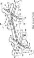
Ein einstufiger Verteiler
Ein Fachmann mit gewöhnlichen Fähigkeiten wird im Umfang der vorliegenden Erfindung alternative Ausführungsformen des Verteilers
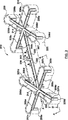
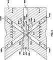
Ein Schmelzesplitter
In einer anderen in den
Rückbeziehend auf
Wie in
Die
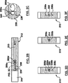
Wie am besten in den
Rückbeziehend auf
Der Schmelzesplitter
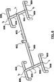
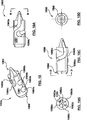
Ein Fachmann mit gewöhnlichen Fähigkeiten kann erkennen, dass ein Schmelzesplitter Strömungswege, Wegeinlässe und Wegauslässe aufweisen kann, die unterschiedlich in ihrer Anzahl und Geometrie sind, abhängig von der Anzahl, der Position und der Richtung der Strömung durch die von einem bestimmten Verteilerblock bereitgestellten sekundären Schmelzekanäle. Wenn zum Beispiel ein Hauptschmelzekanal sich in fünf oder mehr sekundäre Schmelzekanäle aufspaltet, dann können einem Schmelzesplitter in Übereinstimmung mit einer Ausführungsform der Erfindung zusätzliche Strömungswege hinzugefügt werden, um ein im Wesentlichen gleiches Volumen an Schmelzematerial zu jedem sekundären Schmelzekanal zu leiten. In gleicher Weise kann, wenn ein Hauptschmelzekanal sich in zwei oder drei sekundäre Schmelzekanäle aufspaltet, der Schmelzesplitter weniger Strömungswege aufweisen, um sich entsprechend mit den sekundären Schmelzekanälen abzustimmen. In einer in den
Daher werden in der vorliegenden Erfindung verschiedene alternative Ausführungsformen von Schmelzesplittern in Erwägung gezogen, mit der Maßgabe, dass die Schmelzesplitter Schmelzmaterial in im Wesentlichen gleiche Volumina aufspalten und das Schmelzematerial, wie gewünscht, in bestimmte stromabwärtige Schmelzekanäle leitet, basierend auf die besonderen Anordnungen eines Verteilers. Weiter kann ein Schmelzesplitter in Übereinstimmung mit einer Ausführungsform der Erfindung angepasst sein, dort positioniert zu werden, wo der Einlasskanal des Verteilers sich aufspaltet in zwei oder mehrere Hauptschmelzekanäle, die in der gleichen Ebene liegen wie der Einlasskanal.Thus, various alternative embodiments of melt chips are contemplated in the present invention, provided that the melt chips split melt material into substantially equal volumes and direct the melt material, as desired, into particular downstream melt channels based on the particular arrangements of a manifold. Further, a melt splitter, in accordance with an embodiment of the invention, may be adapted to be positioned where the inlet channel of the distributor splits into two or more main melt channels that lie in the same plane as the inlet channel.
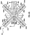
Eine einstufige Verteilerschmelzekanalanordnung in Übereinstimmung mit einer anderen Ausführungsform der Erfindung ist schematisch in
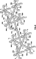
Eine einstufige Verteilerschmelzekanalanordnung in Übereinstimmung mit einer anderen Ausführungsform der Erfindung ist schematisch in
Eine einstufige Verteilerschmelzekanalanordnung in Übereinstimmung mit einer anderen Ausführungsform der Erfindung wird schematisch in
Während verschiedene Ausführungsformen der vorliegenden Erfindung oben beschrieben wurden, ist es selbstverständlich, dass sie lediglich als Beispiel und nicht als Beschränkung präsentiert wurden. Es ist für den Fachmann in der entsprechenden Technik offensichtlich, dass verschiedene Änderungen in der Form und im Detail gemacht werden können ohne sich von dem Umfang und Wesen der Erfindung zu entfernen. Es ist auch verständlich, dass jedes Merkmal jeder hierin diskutierten Ausführungsform und jeder hierin zitierten Bezugnahme verwendet werden kann in Kombination mit den Merkmalen jeder anderen Ausführungsform. Daher soll die Breite und der Umfang der vorliegenden Erfindung nicht durch irgendeine der oben beschriebenen exemplarischen Ausführungsformen beschränkt werden, sondern soll nur in Übereinstimmung mit den folgenden Ansprüchen und ihren Entsprechungen definiert werden. Alle hierin diskutierten Patente und Veröffentlichungen sind durch den Bezug hierin in ihrer Gesamtheit aufgenommen.While various embodiments of the present invention have been described above, it is to be understood that they have been presented by way of example only, and not limitation. It will be apparent to those skilled in the art that various changes in form and detail may be made without departing from the scope and spirit of the invention. It will also be understood that each feature of each embodiment discussed herein and any reference cited herein may be used in combination with the features of any other embodiment. Therefore, the breadth and scope of the present invention should not be limited by any of the above-described exemplary embodiments, but should be defined only in accordance with the following claims and their equivalents. All patents and publications discussed herein are incorporated by reference herein in their entirety.
Claims (16)
Applications Claiming Priority (2)
| Application Number | Priority Date | Filing Date | Title |
|---|---|---|---|
| US12/781,978 | 2010-05-18 | ||
| US12/781,978 US8241032B2 (en) | 2010-05-18 | 2010-05-18 | Single level manifold for an injection molding apparatus |
Publications (1)
| Publication Number | Publication Date |
|---|---|
| DE102011108564A1 true DE102011108564A1 (en) | 2011-11-24 |
Family
ID=44900655
Family Applications (1)
| Application Number | Title | Priority Date | Filing Date |
|---|---|---|---|
| DE102011108564A Ceased DE102011108564A1 (en) | 2010-05-18 | 2011-05-16 | Single-stage distributor for an injection molding device |
Country Status (3)
| Country | Link |
|---|---|
| US (1) | US8241032B2 (en) |
| CN (1) | CN102320104B (en) |
| DE (1) | DE102011108564A1 (en) |
Cited By (2)
| Publication number | Priority date | Publication date | Assignee | Title |
|---|---|---|---|---|
| WO2013037358A1 (en) * | 2011-09-16 | 2013-03-21 | Ksm Castings Group Gmbh | Three-plate die casting tool having a gating system, and gating system |
| WO2021073697A1 (en) * | 2019-10-15 | 2021-04-22 | Reifenhäuser GmbH & Co. KG Maschinenfabrik | Melt conveyor for an extrusion tool of an extrusion system, extrusion tool, extrusion system and method for operating an extrusion system of this type |
Families Citing this family (16)
| Publication number | Priority date | Publication date | Assignee | Title |
|---|---|---|---|---|
| WO2011081694A1 (en) * | 2009-12-31 | 2011-07-07 | Husky Injection Molding Systems Ltd. | Mold-runner system having independently controllable shooting-pot assemblies |
| CN103442874A (en) * | 2011-02-18 | 2013-12-11 | 赫斯基注塑系统有限公司 | Die tool system including a one-piece manifold assembly placing each inlet in fluid communication with multiple outlets |
| JP5874493B2 (en) * | 2012-03-29 | 2016-03-02 | セイコーエプソン株式会社 | Mold for metal powder injection molding |
| CN102700076A (en) * | 2012-06-14 | 2012-10-03 | 苏州腾行精密模具有限公司 | Die runner structure and rubber die with same |
| US9510646B2 (en) * | 2012-07-17 | 2016-12-06 | Nike, Inc. | Article of footwear having a flexible fluid-filled chamber |
| US8690563B2 (en) * | 2012-07-27 | 2014-04-08 | Mold-Masters (2007) Limited | Hot runner manifolds interconnected in a common plane |
| CN104169061B (en) * | 2012-09-27 | 2016-07-06 | 奥林巴斯株式会社 | Hot runner forming device and hot runner nozzle |
| US10076860B2 (en) * | 2013-09-29 | 2018-09-18 | Husky Injection Molding Systems Ltd. | Unitary monolithically formed injection-molding apparatuses |
| CN103640167A (en) * | 2013-11-11 | 2014-03-19 | 吴中区木渎蒯斌模具加工厂 | Blanking plug rear end cover injection mould |
| CN103737795A (en) * | 2013-11-30 | 2014-04-23 | 苏州市旭正模具厂 | American-system connector outer-lower housing molding plastic mold |
| CN103737796A (en) * | 2013-11-30 | 2014-04-23 | 苏州市旭正模具厂 | American-system connector inner-upper housing molding plastic mold |
| KR101822565B1 (en) * | 2016-02-26 | 2018-01-26 | 서울과학기술대학교 산학협력단 | Injection molded lens using hot runner |
| DE102017113885A1 (en) * | 2017-06-22 | 2018-12-27 | Günther Heisskanaltechnik Gmbh | Distributor device for an injection molding nozzle, injection molding nozzle with distributor device and injection molding tool with injection molding nozzle and distributor device |
| CN108407242B (en) * | 2018-05-11 | 2023-10-27 | 珠海格力精密模具有限公司 | Mould |
| DE102019106975A1 (en) * | 2019-03-19 | 2020-09-24 | EWIKON Heißkanalsysteme GmbH | Hot or cold runner device for an injection molding tool with an exchangeable deflection and distribution insert |
| JP7711454B2 (en) * | 2021-07-05 | 2025-07-23 | 住友電気工業株式会社 | Coating device and coating method |
Family Cites Families (41)
| Publication number | Priority date | Publication date | Assignee | Title |
|---|---|---|---|---|
| FR1330440A (en) | 1962-08-01 | 1963-06-21 | Honda Motor Co Ltd | Further training in injection molding machines for thermoplastics |
| CH452179A (en) | 1966-08-19 | 1968-05-31 | Segmueller Ag | Hot runner injection molding tool |
| US3470914A (en) | 1967-01-04 | 1969-10-07 | Du Pont | Flow inversion apparatus and process |
| DE2114465B2 (en) | 1971-03-25 | 1973-07-19 | Holstein & Kappert Maschmenfabnk Phomx GmbH, 4600 Dortmund | DEVICE FOR DISTRIBUTING PLASTIC MATERIALS |
| DE2338458A1 (en) | 1973-07-28 | 1975-02-06 | Karl Hehl | MULTIPLE NOZZLE OF ONE INJECTION MOLDING MACHINE |
| US3940224A (en) | 1974-01-16 | 1976-02-24 | Package Machinery Company | Constant velocity manifold for injection molding machine |
| JPS559849A (en) | 1978-07-06 | 1980-01-24 | Sharp Corp | Metallic (forming) mould |
| US4256140A (en) | 1979-12-06 | 1981-03-17 | The Continental Group, Inc. | Two-piece hot runner manifold |
| JPS6015113A (en) | 1983-07-08 | 1985-01-25 | ザ・ブロ−ドウエイ・カンパニ−ズ・インコ−ポレ−テツド | Manifold for injection molding machine |
| JPH0798344B2 (en) | 1986-10-24 | 1995-10-25 | 大日本印刷株式会社 | Hot Tranna |
| EP0293756A3 (en) | 1987-06-01 | 1989-12-06 | Husky Injection Molding Systems Ltd. | Method of processing molten plastic materials |
| JPH06262650A (en) | 1993-02-04 | 1994-09-20 | Sadao Shimizu | Production of manifold for injection molding machine having resin passage having smooth curve built therein |
| JP3189262B2 (en) | 1994-09-22 | 2001-07-16 | 三菱マテリアル株式会社 | Multi-cavity mold device |
| US5683731A (en) | 1995-12-11 | 1997-11-04 | Husky Injection Molding Systems Ltd. | Melt flow redistributor |
| US5762976A (en) | 1996-02-06 | 1998-06-09 | Brown; Paul Phillip | Hot runner manifold for thermally sensitive resins |
| WO1998038021A1 (en) | 1997-02-25 | 1998-09-03 | Jes Tougaard Gram | Procedure and machine for multi component moulding |
| EP1023152B1 (en) | 1997-10-14 | 2004-11-24 | The Penn State Research Foundation | Method and apparatus for balancing the filling of injection molds |
| US6235230B1 (en) | 1999-04-02 | 2001-05-22 | Acushnet Company | Ring gate for retractable pin injection molding |
| US6089468A (en) | 1999-11-08 | 2000-07-18 | Husky Injection Molding Systems Ltd. | Nozzle tip with weld line eliminator |
| US6572361B2 (en) | 1999-11-08 | 2003-06-03 | Husky Injection Molding Systems, Ltd. | Injection molding machine having a mixer insert |
| US6544028B2 (en) | 1999-11-08 | 2003-04-08 | Husky Injection Molding Systems, Ltd | Injection molding machine having a mixer insert |
| US6450798B1 (en) | 2000-02-04 | 2002-09-17 | Avaya Technology Corp. | Apparatus for multiple cavity injection molding |
| WO2002000414A1 (en) | 2000-06-28 | 2002-01-03 | Beaumont Runner Technologies, Inc. | Method and apparatus for balancing flowing conditions of laminar flowing materials |
| AU2003303887B2 (en) | 2003-02-04 | 2007-04-26 | Husky Injection Molding Systems Ltd. | Hot runner manifold system |
| US7320589B2 (en) | 2003-02-26 | 2008-01-22 | Mold-Masters (2007) Limited | Hot runner manifold plug for rheological balance in hot runner injection molding |
| WO2004103670A2 (en) | 2003-05-20 | 2004-12-02 | Kortec, Inc. | Apparatus and method for fluid distribution |
| TWI277501B (en) * | 2004-07-02 | 2007-04-01 | Plastic Engineering & Technica | Machined manifold and method of making same |
| DE102004043949B4 (en) | 2004-09-11 | 2008-05-29 | Incoe International, Inc. | Device for the selective distribution of a non-Newtonian liquid flowing through a channel, such as a plastic melt |
| CA2542374A1 (en) * | 2005-04-07 | 2006-10-07 | Mold-Masters Limited | Configurable manifold |
| EP1885541B1 (en) | 2005-05-17 | 2017-01-18 | BEAUMONT, John P. | Adjustable melt rotation positioning device and method |
| US7666335B2 (en) | 2006-05-08 | 2010-02-23 | Beaumont Technologies, Inc. | Controlling warpage through melt rotation technology |
| KR100754803B1 (en) | 2006-08-09 | 2007-09-03 | 삼성전기주식회사 | Injection molding uniform filling device |
| KR20080013540A (en) | 2006-08-09 | 2008-02-13 | 삼성전기주식회사 | Injection molding uniform filling device |
| KR100798373B1 (en) | 2006-08-21 | 2008-01-28 | 삼성전기주식회사 | Injection Molding Filling Device |
| DE202006018031U1 (en) | 2006-11-24 | 2008-04-03 | Günther Heisskanaltechnik Gmbh | Arrangement for closing channel sections in a hot or cold runner distributor |
| US20080296805A1 (en) | 2007-05-31 | 2008-12-04 | Husky Injection Molding Systems Ltd. | Hot Runner Melt Pre-Compression |
| US20090047373A1 (en) | 2007-08-16 | 2009-02-19 | Husky Injection Molding Systems Ltd. | Bridge Runner System |
| US20090047376A1 (en) | 2007-08-16 | 2009-02-19 | Husky Injection Molding Systems Ltd. | Melt Distribution Apparatus |
| EP2183090B1 (en) | 2007-08-24 | 2012-06-06 | Husky Injection Molding Systems Ltd. | An injection molding system comprising an apparatus for controlling melt flow in a melt distribution network |
| US20090136614A1 (en) | 2007-11-26 | 2009-05-28 | Husky Injection Molding Systems Ltd. | Hot Runner Manifold Plug |
| DE102009014113A1 (en) | 2009-03-24 | 2010-09-30 | Günther Heisskanaltechnik Gmbh | Rotary device for fluid mass in e.g. hot channel distributor of injection molding device, has stopper that is fixed within region of crossing points in one of channel sections, where turning element is formed at and/or in stopper |
-
2010
- 2010-05-18 US US12/781,978 patent/US8241032B2/en active Active
-
2011
- 2011-05-16 DE DE102011108564A patent/DE102011108564A1/en not_active Ceased
- 2011-05-18 CN CN201110177538.6A patent/CN102320104B/en active Active
Cited By (3)
| Publication number | Priority date | Publication date | Assignee | Title |
|---|---|---|---|---|
| WO2013037358A1 (en) * | 2011-09-16 | 2013-03-21 | Ksm Castings Group Gmbh | Three-plate die casting tool having a gating system, and gating system |
| US9434001B2 (en) | 2011-09-16 | 2016-09-06 | Ksm Castings Group Gmbh | Three-plate die casting tool having a gating system, and gating system |
| WO2021073697A1 (en) * | 2019-10-15 | 2021-04-22 | Reifenhäuser GmbH & Co. KG Maschinenfabrik | Melt conveyor for an extrusion tool of an extrusion system, extrusion tool, extrusion system and method for operating an extrusion system of this type |
Also Published As
| Publication number | Publication date |
|---|---|
| CN102320104B (en) | 2014-09-24 |
| US8241032B2 (en) | 2012-08-14 |
| CN102320104A (en) | 2012-01-18 |
| US20110287129A1 (en) | 2011-11-24 |
Similar Documents
| Publication | Publication Date | Title |
|---|---|---|
| DE102011108564A1 (en) | Single-stage distributor for an injection molding device | |
| DE602004008611T2 (en) | STATIC MIXER FOR A SPRAYING SYSTEM | |
| DE69827834T2 (en) | METHOD AND DEVICE FOR BALANCING THE FILLING OF SPRAY FORMS | |
| EP3215342B1 (en) | Co-injection nozzle comprising integrated back-flow barrier | |
| EP3191287B1 (en) | Method and injection-moulding nozzle for producing injection-moulded parts from plastic | |
| DE102004009320A1 (en) | Hot runner system for controlling cross-sectional asymmetric condition of laminar flowing material comprises flow rotator having bending path for orienting outlet relative to inlet to divide equally the condition between two downstreams | |
| DE102013201871A1 (en) | Vortex generator for rotor blade of wind turbine for influencing air flow on surface of rotor blade, has base plate with upper side and wing with side surfaces, where wing is arranged transverse to base plate at upper side | |
| EP3215343B1 (en) | Co-injection nozzle for an injection moulding device for producing multi-layered injection-moulded products | |
| DE1435552A1 (en) | Spinneret | |
| EP2032329B1 (en) | Mould cavity with decoupled cooling-channel routing | |
| EP2032330B1 (en) | Mould cavity with decoupled cooling-channel routing | |
| DE102007052597A1 (en) | Angle adapter and sprue system for a sprue adapter | |
| DE68913467T2 (en) | Spinneret for the production of membranes from an organic material with at least one longitudinal channel. | |
| DE2114465A1 (en) | Injection mould distributor blocks - with uniform feed | |
| DE102006004928A1 (en) | Improved neck back cooling | |
| DE69118336T2 (en) | Melt distributor block for several mold cavities | |
| DE102019127956A1 (en) | SIDE INJECTION NOZZLE AND INJECTION MOLDING TOOL | |
| DE202016004378U1 (en) | Hot runner system for side casting with a nozzle melt manifold divider | |
| DE10246701B4 (en) | Injection molding device and nozzle with a gap seal between nozzle components | |
| AT515727B1 (en) | gate nozzle | |
| DE102022103624A1 (en) | nozzle tip | |
| EP3523109B1 (en) | Injection moulding machine for manufacturing fibre-reinforced plastic parts | |
| DE102019127972A1 (en) | INJECTION MOLD WITH A SIDE INJECTION NOZZLE | |
| DE102013021752B3 (en) | Connectors, as well as tools and methods for its manufacture | |
| AT520389A2 (en) | Method for producing plastic injection-molded parts |
Legal Events
| Date | Code | Title | Description |
|---|---|---|---|
| R012 | Request for examination validly filed | ||
| R016 | Response to examination communication | ||
| R002 | Refusal decision in examination/registration proceedings | ||
| R003 | Refusal decision now final |