DE102012024904A1 - stacker - Google Patents
stacker Download PDFInfo
- Publication number
- DE102012024904A1 DE102012024904A1 DE102012024904A DE102012024904A DE102012024904A1 DE 102012024904 A1 DE102012024904 A1 DE 102012024904A1 DE 102012024904 A DE102012024904 A DE 102012024904A DE 102012024904 A DE102012024904 A DE 102012024904A DE 102012024904 A1 DE102012024904 A1 DE 102012024904A1
- Authority
- DE
- Germany
- Prior art keywords
- veneer
- gripper
- sheet
- stacking device
- feed direction
- Prior art date
- Legal status (The legal status is an assumption and is not a legal conclusion. Google has not performed a legal analysis and makes no representation as to the accuracy of the status listed.)
- Granted
Links
- 238000012806 monitoring device Methods 0.000 claims description 4
- 230000002996 emotional effect Effects 0.000 claims 1
- 239000003292 glue Substances 0.000 description 3
- 239000011120 plywood Substances 0.000 description 3
- 238000010276 construction Methods 0.000 description 2
- 230000007423 decrease Effects 0.000 description 2
- 230000001360 synchronised effect Effects 0.000 description 2
- BUHVIAUBTBOHAG-FOYDDCNASA-N (2r,3r,4s,5r)-2-[6-[[2-(3,5-dimethoxyphenyl)-2-(2-methylphenyl)ethyl]amino]purin-9-yl]-5-(hydroxymethyl)oxolane-3,4-diol Chemical compound COC1=CC(OC)=CC(C(CNC=2C=3N=CN(C=3N=CN=2)[C@H]2[C@@H]([C@H](O)[C@@H](CO)O2)O)C=2C(=CC=CC=2)C)=C1 BUHVIAUBTBOHAG-FOYDDCNASA-N 0.000 description 1
- 230000000903 blocking effect Effects 0.000 description 1
- 238000007664 blowing Methods 0.000 description 1
- 238000011109 contamination Methods 0.000 description 1
- 238000006073 displacement reaction Methods 0.000 description 1
- 230000000694 effects Effects 0.000 description 1
- 238000012544 monitoring process Methods 0.000 description 1
- 210000002445 nipple Anatomy 0.000 description 1
- 238000010186 staining Methods 0.000 description 1
- 238000011144 upstream manufacturing Methods 0.000 description 1
Images


Classifications
-
- B—PERFORMING OPERATIONS; TRANSPORTING
- B65—CONVEYING; PACKING; STORING; HANDLING THIN OR FILAMENTARY MATERIAL
- B65G—TRANSPORT OR STORAGE DEVICES, e.g. CONVEYORS FOR LOADING OR TIPPING, SHOP CONVEYOR SYSTEMS OR PNEUMATIC TUBE CONVEYORS
- B65G57/00—Stacking of articles
- B65G57/02—Stacking of articles by adding to the top of the stack
- B65G57/03—Stacking of articles by adding to the top of the stack from above
-
- B—PERFORMING OPERATIONS; TRANSPORTING
- B65—CONVEYING; PACKING; STORING; HANDLING THIN OR FILAMENTARY MATERIAL
- B65H—HANDLING THIN OR FILAMENTARY MATERIAL, e.g. SHEETS, WEBS, CABLES
- B65H9/00—Registering, e.g. orientating, articles; Devices therefor
- B65H9/10—Pusher and like movable registers; Pusher or gripper devices which move articles into registered position
- B65H9/103—Pusher and like movable registers; Pusher or gripper devices which move articles into registered position acting by friction or suction on the article for pushing or pulling it into registered position, e.g. against a stop
- B65H9/105—Pusher and like movable registers; Pusher or gripper devices which move articles into registered position acting by friction or suction on the article for pushing or pulling it into registered position, e.g. against a stop using suction means
-
- B—PERFORMING OPERATIONS; TRANSPORTING
- B65—CONVEYING; PACKING; STORING; HANDLING THIN OR FILAMENTARY MATERIAL
- B65H—HANDLING THIN OR FILAMENTARY MATERIAL, e.g. SHEETS, WEBS, CABLES
- B65H29/00—Delivering or advancing articles from machines; Advancing articles to or into piles
- B65H29/24—Delivering or advancing articles from machines; Advancing articles to or into piles by air blast or suction apparatus
- B65H29/241—Suction devices
-
- B—PERFORMING OPERATIONS; TRANSPORTING
- B65—CONVEYING; PACKING; STORING; HANDLING THIN OR FILAMENTARY MATERIAL
- B65H—HANDLING THIN OR FILAMENTARY MATERIAL, e.g. SHEETS, WEBS, CABLES
- B65H29/00—Delivering or advancing articles from machines; Advancing articles to or into piles
- B65H29/26—Delivering or advancing articles from machines; Advancing articles to or into piles by dropping the articles
- B65H29/34—Delivering or advancing articles from machines; Advancing articles to or into piles by dropping the articles from supports slid from under the articles
-
- B—PERFORMING OPERATIONS; TRANSPORTING
- B65—CONVEYING; PACKING; STORING; HANDLING THIN OR FILAMENTARY MATERIAL
- B65H—HANDLING THIN OR FILAMENTARY MATERIAL, e.g. SHEETS, WEBS, CABLES
- B65H31/00—Pile receivers
- B65H31/04—Pile receivers with movable end support arranged to recede as pile accumulates
- B65H31/08—Pile receivers with movable end support arranged to recede as pile accumulates the articles being piled one above another
- B65H31/10—Pile receivers with movable end support arranged to recede as pile accumulates the articles being piled one above another and applied at the top of the pile
-
- B—PERFORMING OPERATIONS; TRANSPORTING
- B65—CONVEYING; PACKING; STORING; HANDLING THIN OR FILAMENTARY MATERIAL
- B65H—HANDLING THIN OR FILAMENTARY MATERIAL, e.g. SHEETS, WEBS, CABLES
- B65H43/00—Use of control, checking, or safety devices, e.g. automatic devices comprising an element for sensing a variable
-
- B—PERFORMING OPERATIONS; TRANSPORTING
- B65—CONVEYING; PACKING; STORING; HANDLING THIN OR FILAMENTARY MATERIAL
- B65H—HANDLING THIN OR FILAMENTARY MATERIAL, e.g. SHEETS, WEBS, CABLES
- B65H2406/00—Means using fluid
- B65H2406/30—Suction means
- B65H2406/34—Suction grippers
- B65H2406/342—Suction grippers being reciprocated in a rectilinear path
-
- B—PERFORMING OPERATIONS; TRANSPORTING
- B65—CONVEYING; PACKING; STORING; HANDLING THIN OR FILAMENTARY MATERIAL
- B65H—HANDLING THIN OR FILAMENTARY MATERIAL, e.g. SHEETS, WEBS, CABLES
- B65H2406/00—Means using fluid
- B65H2406/30—Suction means
- B65H2406/34—Suction grippers
- B65H2406/343—Details of sucking member
-
- B—PERFORMING OPERATIONS; TRANSPORTING
- B65—CONVEYING; PACKING; STORING; HANDLING THIN OR FILAMENTARY MATERIAL
- B65H—HANDLING THIN OR FILAMENTARY MATERIAL, e.g. SHEETS, WEBS, CABLES
- B65H2406/00—Means using fluid
- B65H2406/30—Suction means
- B65H2406/36—Means for producing, distributing or controlling suction
- B65H2406/365—Means for producing, distributing or controlling suction selectively blowing or sucking
-
- B—PERFORMING OPERATIONS; TRANSPORTING
- B65—CONVEYING; PACKING; STORING; HANDLING THIN OR FILAMENTARY MATERIAL
- B65H—HANDLING THIN OR FILAMENTARY MATERIAL, e.g. SHEETS, WEBS, CABLES
- B65H2701/00—Handled material; Storage means
- B65H2701/10—Handled articles or webs
- B65H2701/19—Specific article or web
- B65H2701/1938—Veneer sheet
Landscapes
- Engineering & Computer Science (AREA)
- Mechanical Engineering (AREA)
- Discharge By Other Means (AREA)
- Veneer Processing And Manufacture Of Plywood (AREA)
- Pile Receivers (AREA)
Abstract
Eine im Wesentlichen horizontale Vorrichtung zum Stapeln von Furnierblättern (1, 2), die ein von einem Förderer (7) bewegtes Halteelement umfasst, das sich in Vorschubrichtung in einem Freigabebereich von unterhalb des zu stapelnden Furniers (2) wegbewegt, sowie gesteuerte Mittel zum Stoppen des zu stapelnden Furniers in einer korrigierten Position an einem Freigabepunkt. Bei den Mitteln zum Stoppen des zu stapelnden Furniers handelt es sich um einen Greifer (10), der das hintere Ende des Furniers (2) von unten ergreift und sich nach oben und unten, in Vorschubrichtung des Furniers und quer zu dieser Vorschubrichtung bewegt, wobei sich ein Angriffspunkt des Greifers am Furnier an der Hinterkante in Vorschubrichtung des Furniers befindet, in einem Abstand in Vorschubrichtung vom quer verlaufenden Verfahrweg des Greifers.A substantially horizontal apparatus for stacking veneer sheets (1, 2) comprising a holding member moved by a conveyor (7), which moves away in the advancing direction in a release area from below the veneer (2) to be stacked, and controlled means for stopping of the veneer to be stacked in a corrected position at a release point. The means for stopping the veneer to be stacked is a gripper (10) which grips the rear end of the veneer (2) from below and moves up and down, in the direction of advance of the veneer and transversely to this direction of advance, an attack point of the gripper is located on the veneer at the trailing edge in the feed direction of the veneer, at a distance in the feed direction from the transverse travel of the gripper.
Description
Gegenstand der vorliegenden Erfindung ist eine Stapelvorrichtung zum Stapeln von Sperrholzfurnieren.The subject of the present invention is a stacking device for stacking plywood veneers.
Mit der Vorrichtung können auf Maß geschnittene Furnierblätter zu einem Stapel aufeinander geschichtet werden, wobei sich die Furnierblätter genau positionieren lassen.With the device veneer cut veneer sheets can be stacked to form a stack, with the veneer sheets can be positioned accurately.
Derartige Positionier- und Stapelvorrichtungen werden beispielsweise zum Stapeln von beleimten Blättern verwendet, die zu Sperrholz verpresst werden. Der Stapelvorrichtung vorgeschaltet ist ein Überwachungsgerät zur Aufzeichnung von Lage und Ausrichtung eines zur Stapelvorrichtung mit Hilfe eines Förderers bewegten Blatts. Die vom Überwachungsgerät aufgezeichneten Informationen bezüglich Lage und Ausrichtung werden zur Steuerung der Elemente verwendet, mit denen das Blatt auf dem Stapel positioniert wird.Such positioning and stacking devices are used for example for stacking glued leaves, which are pressed into plywood. Upstream of the stacking device is a monitoring device for recording the position and orientation of a sheet moved to the stacking device by means of a conveyor. The position and orientation information recorded by the monitor is used to control the elements used to position the sheet on the stack.
Es ist bekannt, einen Horizontalförderer mit in Transportrichtung alternierenden Halte- und Freigabesektionen einzusetzen, um ein zu stapelndes Blatt zu bewegen und an einem Stapelpunkt freizugeben. Die Transportsektion ist im Wesentlichen entsprechend den Abmessungen des Blatts dimensioniert und stützt das Blatt von unten ab. Auf die Haltesektion folgt vor der nächsten Haltesektion ein Zwischenraum, durch den das Blatt von einer Haltesektion fallen kann, die sich unter Blockieren des Vorschubs des Blatts darunter wegbewegt. Eine derartige Stapelvorrichtung ist beispielsweise in der
Gegenstand der vorliegenden Erfindung ist es, eine Stapelvorrichtung für Furnierblätter zur Verfügung zu stellen, mit der Furnierblätter positioniert gestapelt werden können. Geräte zur Aufzeichnung von Lage und Ausrichtung des Furniers durch Überwachung desselben am Förderer vor dem Stapeln können verwendet werden, um die Positionierung festzulegen. Informationen für die Steuergeräte der Antriebe der Stapelvorrichtung liefern die Aufzeichnungsgeräte. Eine Positionierung ermöglicht eine wesentlich bessere Stapelgenauigkeit, als dies beim Stapeln an Anschlägen möglich ist.The object of the present invention is to provide a stacking device for veneer sheets, with which veneer sheets can be stacked in position. Equipment for recording the position and orientation of the veneer by monitoring it on the conveyor prior to stacking may be used to determine positioning. Information for the control units of the drives of the stacking device is provided by the recording devices. Positioning allows much better stacking accuracy than is possible with stacks on stoppers.
Die Grundkonstruktion der Vorrichtung ist bekannt, d. h. sie umfasst einen Förderer, der sich von unterhalb des Furniers an einem Freigabepunkt wegbewegt sowie Mittel zum Stoppen des zu stapelnden Furniers am Freigabepunkt zur Korrektur der Ausrichtung. Erfindungsgemäß handelt es sich bei den Mitteln zum Stoppen des Furniers um Greifer, die die Hinterkante des Furniers von unten ergreifen und nach oben/unten, in Vorschubrichtung des Furniers und quer zur Vorschubrichtung bewegt werden können, wobei sich der Angriffspunkt der Greifer am Furnier an der Hinterkante in Vorschubrichtung des Furniers befindet, in einem Abstand vom quer verlaufenden Verfahrweg der Greifer.The basic construction of the device is known, d. H. it comprises a conveyor which moves away from below the veneer at a release point and means for stopping the veneer to be stacked at the release point for correcting the alignment. According to the invention, the means for stopping the veneer are grippers which grasp the trailing edge of the veneer from below and can be moved up / down, in the direction of advance of the veneer and transversely to the direction of advance, the point of engagement of the grippers on the veneer on the veneer Trailing edge is in the feed direction of the veneer, at a distance from the transverse travel of the gripper.
Die Erfindung wird anhand der beigefügten Zeichnung näher beschrieben. Dabei zeigt:The invention will be described in more detail with reference to the accompanying drawings. Showing:
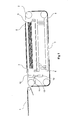
Die Vorrichtung besitzt Greifer
Die Greifer
In
Mit Hilfe dieser Maschinenbauteile kann ein auf dem Förderer
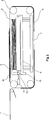
Die Greifer
Wenn das Furnierblatt den Stapelbereich erreicht, kann es auch seitlich zur Vorschubrichtung und/oder gedreht zur Vorschubrichtung verschoben werden, wobei diese Position korrigiert werden muss, um einen entsprechenden Stapel zu erzielen. Zu diesem Zweck können die Greifer
Um die Vorrichtung vollständig steuern zu können, muss sie mit einem Überwachungsgerät ausgerüstet sein, mit dem die Lage und Ausrichtung des Furniers
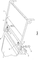
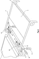
Einer der Greifer
Beim Aufeinanderschichten eines Furnierstapels ist es das Ziel, die Furnieroberflächen so auszuwählen, dass sie so wenig Risse und Astlöcher wie möglich aufweisen. Die Furnierblätter sind jedoch beleimt und der Leim kann über den Rand des Furnierblatts hervorstehen, was wiederum die Greifer (
Eine Verschmutzung der Greifer kann auch dadurch verhindert werden, dass man den Sauger der Greifer verschließt, beispielsweise mit Antrieben oder mit der Klappe
In obiger Beschreibung wurde die Erfindung unter Verwendung zweier Greifer
ZITATE ENTHALTEN IN DER BESCHREIBUNG QUOTES INCLUDE IN THE DESCRIPTION
Diese Liste der vom Anmelder aufgeführten Dokumente wurde automatisiert erzeugt und ist ausschließlich zur besseren Information des Lesers aufgenommen. Die Liste ist nicht Bestandteil der deutschen Patent- bzw. Gebrauchsmusteranmeldung. Das DPMA übernimmt keinerlei Haftung für etwaige Fehler oder Auslassungen.This list of the documents listed by the applicant has been generated automatically and is included solely for the better information of the reader. The list is not part of the German patent or utility model application. The DPMA assumes no liability for any errors or omissions.
Zitierte PatentliteraturCited patent literature
- US 3807553 [0004] US 3807553 [0004]
Claims (8)
Applications Claiming Priority (2)
| Application Number | Priority Date | Filing Date | Title |
|---|---|---|---|
| FI20116297A FI123711B (en) | 2011-12-21 | 2011-12-21 | Stacking |
| FI20116297 | 2011-12-21 |
Publications (2)
| Publication Number | Publication Date |
|---|---|
| DE102012024904A1 true DE102012024904A1 (en) | 2013-06-27 |
| DE102012024904B4 DE102012024904B4 (en) | 2021-01-21 |
Family
ID=48048771
Family Applications (1)
| Application Number | Title | Priority Date | Filing Date |
|---|---|---|---|
| DE102012024904.7A Active DE102012024904B4 (en) | 2011-12-21 | 2012-12-20 | Stacking device |
Country Status (6)
| Country | Link |
|---|---|
| US (1) | US8951003B2 (en) |
| CN (1) | CN103171923B (en) |
| CA (1) | CA2799030C (en) |
| DE (1) | DE102012024904B4 (en) |
| FI (1) | FI123711B (en) |
| IT (1) | ITMI20122189A1 (en) |
Families Citing this family (8)
| Publication number | Priority date | Publication date | Assignee | Title |
|---|---|---|---|---|
| FI123653B (en) * | 2010-11-23 | 2013-08-30 | Raute Oyj | Device for clipping veneer sheets |
| CN104860074B (en) * | 2014-02-26 | 2017-08-25 | 宝山钢铁股份有限公司 | A kind of control method of finishing printed line finished product stacking |
| TWM514403U (en) * | 2015-05-26 | 2015-12-21 | Foxlink Image Tech Co Ltd | The output mechanism |
| CN105712092B (en) * | 2016-04-28 | 2018-04-13 | 佛山科学技术学院 | A kind of Full-automatic section bar Palletizer and its palletizing method |
| EP3509856A4 (en) | 2016-09-09 | 2020-04-29 | Hewlett-Packard Development Company, L.P. | Sequential clamping |
| CN115091601B (en) * | 2022-07-11 | 2024-01-12 | 中国新型建材设计研究院有限公司 | Gypsum board plywood equipment and gypsum board production line |
| CN117816592B (en) * | 2024-01-08 | 2024-07-16 | 江苏鑫埭信息科技有限公司 | Electronic equipment sorting device based on Internet of things |
| CN118220844B (en) * | 2024-05-23 | 2024-09-24 | 靖江市永盛光电科技有限公司 | Full-automatic backlight film stacking machine |
Citations (1)
| Publication number | Priority date | Publication date | Assignee | Title |
|---|---|---|---|---|
| US3807553A (en) | 1972-03-13 | 1974-04-30 | Fmc Corp | Sheet material stacking apparatus |
Family Cites Families (24)
| Publication number | Priority date | Publication date | Assignee | Title |
|---|---|---|---|---|
| GB446886A (en) | 1934-12-29 | 1936-05-07 | Roland Offsetmaschf | Improvements in and relating to sheet registering devices |
| US3346128A (en) * | 1965-05-18 | 1967-10-10 | Owens Corning Fiberglass Corp | Apparatus for materials handling |
| US3845950A (en) * | 1968-11-22 | 1974-11-05 | B Kuzniak | Material handling apparatus |
| US3583562A (en) * | 1969-01-07 | 1971-06-08 | Coe Mfg Co The | Methods of and apparatus for stacking veneer sheets |
| US3567047A (en) * | 1969-01-22 | 1971-03-02 | Simpson Timber Co | Stacking apparatus for wood veneer and other sheet material |
| US3894638A (en) * | 1973-09-13 | 1975-07-15 | Buckler Ind Inc | Reciprocating stacker for generally laminar articles |
| US4055247A (en) * | 1976-10-22 | 1977-10-25 | The United States Of America As Represented By The United States Energy Research And Development Administration | Explosion containment device |
| CA1194511A (en) * | 1981-04-24 | 1985-10-01 | Friedhelm Mundus | Apparatus for stacking flat articles |
| US5123807A (en) * | 1988-03-12 | 1992-06-23 | Meinan Machinery Works, Inc. | System for stacking veneer sheets conveyed from two different directions |
| US5098079A (en) * | 1990-07-10 | 1992-03-24 | Ark, Inc. | Apparatus for stacking pieces of limp material |
| CN1086193A (en) * | 1992-07-11 | 1994-05-04 | 海德堡印刷机械股份公司 | The method and apparatus of stacking in the middle of the paper |
| DE4314760C2 (en) * | 1993-05-05 | 1995-11-16 | Ltg Lufttechnische Gmbh | Device for stacking sheets |
| DE4433912C2 (en) * | 1994-09-23 | 1996-07-11 | Ltg Lufttechnische Gmbh | Stacking device with upper panel guide |
| DE19549675B4 (en) * | 1995-07-07 | 2005-02-17 | Windmöller & Hölscher Kg | Method for separating stacked flat tube pieces |
| DE19814141C2 (en) | 1998-03-30 | 2003-08-14 | Ltg Holding Gmbh | Method and device for the precise feeding of sheet-like goods to a machining process |
| CH694504A5 (en) * | 1999-02-19 | 2005-02-28 | Elpatronic Ag | A method for cutting metal sheets to metal strips and cutting device for its implementation. |
| US6672585B2 (en) * | 2000-06-02 | 2004-01-06 | Fuji Photo Film Co., Ltd. | Apparatus for stacking sheet members, apparatus for measuring dimensions of sheet members, and apparatus for and method of marking sheet members |
| DE10345703A1 (en) * | 2002-10-25 | 2004-05-13 | Heidelberger Druckmaschinen Ag | Sheet processing machine, especially a rotary printer, has a gripper for transferring sheets from an output transport belt to sheet stacks, with the gripper movement speed adjusted along its path to optimize sheet stacking |
| US6860481B2 (en) * | 2002-11-14 | 2005-03-01 | Nikko Materials Usa, Inc. | Sheet stacking device |
| DE102005002507B4 (en) | 2004-02-05 | 2015-07-02 | Heidelberger Druckmaschinen Ag | Device for machine handling of sheets of substrate |
| JP2008133106A (en) * | 2006-11-29 | 2008-06-12 | Nisca Corp | Sheet stacking device and image forming system equipped therewith |
| US7887040B2 (en) * | 2009-01-09 | 2011-02-15 | J & L Group International, Llc | Sheet deceleration apparatus and method with kicker |
| DE102009000221A1 (en) * | 2009-01-14 | 2010-07-15 | Koenig & Bauer Aktiengesellschaft | Delivery device for sheet-fed offset rotary printing machine, has rotating sheet guiding element arranged along sheet conveying path and designed as rotating belt or cloth, where rear edge of sheet is guided by element |
| FI121873B (en) | 2009-09-09 | 2011-05-31 | Raute Oyj | Procedure for optimal parking of veneer sheets at the laying station |
-
2011
- 2011-12-21 FI FI20116297A patent/FI123711B/en active IP Right Grant
-
2012
- 2012-12-12 US US13/712,061 patent/US8951003B2/en active Active
- 2012-12-18 CA CA2799030A patent/CA2799030C/en active Active
- 2012-12-20 IT IT002189A patent/ITMI20122189A1/en unknown
- 2012-12-20 DE DE102012024904.7A patent/DE102012024904B4/en active Active
- 2012-12-21 CN CN201210599363.2A patent/CN103171923B/en active Active
Patent Citations (1)
| Publication number | Priority date | Publication date | Assignee | Title |
|---|---|---|---|---|
| US3807553A (en) | 1972-03-13 | 1974-04-30 | Fmc Corp | Sheet material stacking apparatus |
Also Published As
| Publication number | Publication date |
|---|---|
| CN103171923B (en) | 2016-12-28 |
| CN103171923A (en) | 2013-06-26 |
| ITMI20122189A1 (en) | 2013-06-22 |
| US8951003B2 (en) | 2015-02-10 |
| CA2799030A1 (en) | 2013-06-21 |
| FI123711B (en) | 2013-09-30 |
| CA2799030C (en) | 2019-04-23 |
| DE102012024904B4 (en) | 2021-01-21 |
| FI20116297L (en) | 2013-06-22 |
| US20130164111A1 (en) | 2013-06-27 |
Similar Documents
| Publication | Publication Date | Title |
|---|---|---|
| DE102012024904B4 (en) | Stacking device | |
| DE3321756A1 (en) | DEVICE FOR STACKING CUTS | |
| DE602005006006T2 (en) | HANDLING UNIT FOR PALLETIZING | |
| DE2130592C3 (en) | Machine for removing the topmost from a stack of glass panes | |
| WO2018166604A1 (en) | Centering device | |
| DE102009040792A1 (en) | Pallet stack manipulator for unstacking device for scheduling pallet stack with pallets nested with each other for unstacking, has centering device to center two pallets of pallet stack to each other | |
| EP1223137B1 (en) | Device for the superposing of sheets in a packet | |
| DE102015112625A1 (en) | Method for destacking veneer sheets | |
| EP2923975B1 (en) | Depalletising device and depalletising method for removing layers of packets from a stack of goods | |
| EP4257313A2 (en) | Panel-dividing system for dividing panel-shaped workpieces and method for the operation thereof | |
| DE19834927A1 (en) | Method for storing and removing piece goods in particular packets, cartons and containers, has suction element associated with the gripping and pulling element to allow handling of soft cartons | |
| DE102020207418A1 (en) | Device for handling printing plates on a printing machine | |
| DE4439913C2 (en) | Bag storage device | |
| DE29916095U1 (en) | Arrangement for conveying and stacking mostly flat and flexible objects, especially gloves | |
| DE10258896A1 (en) | Device for separation of sheets of paper from stack has separation sucker with consisting of housing with sheet guiding face facing uppermost sheet and blast air guiding surfaces extending in direction of rear side of stack | |
| DE102015122943A1 (en) | Method and device for laying veneer sheets | |
| DE2839757C2 (en) | System for covering panels with liner sheets | |
| DE4139887A1 (en) | Machine for stacking panes of glass - has swinging arm with frame fitted with suction pads | |
| DE10224374A1 (en) | Sheet alignment device for printing machine has suction rail that can additionally be moved in or opposite to sheet transport direction to achieve desired sheet position relative to leading edge | |
| DE102010000625A1 (en) | Method for handling i.e. transportation, of paper sheets into or by cutting machine, involves detecting layers of cutting goods in work station, and utilizing surface suction gripper as gripper, which sucks layers at side surfaces | |
| DE19515331C2 (en) | Sheet separator | |
| DE102018133455B4 (en) | Transport method and holding and conveying device | |
| DE397318C (en) | Automatic sheet feeder | |
| DE10057690A1 (en) | Method and device for automatically stacking, separating and allocating workpieces | |
| DE2323339C3 (en) | Device for gathering large sheets of the same size from more than two removal stations |
Legal Events
| Date | Code | Title | Description |
|---|---|---|---|
| R082 | Change of representative |
Representative=s name: PATENTANWAELTE WEICKMANN & WEICKMANN, DE Representative=s name: WEICKMANN & WEICKMANN PATENTANWAELTE - RECHTSA, DE Representative=s name: WEICKMANN & WEICKMANN PATENT- UND RECHTSANWAEL, DE |
|
| R012 | Request for examination validly filed | ||
| R016 | Response to examination communication | ||
| R018 | Grant decision by examination section/examining division | ||
| R020 | Patent grant now final |