DE102012024972A1 - Method for operating multi-camera system of i.e. passenger car, involves limiting parameter values on predetermined value range by adjusting common desired value, and performing image processing algorithm using electronic computing device - Google Patents

Method for operating multi-camera system of i.e. passenger car, involves limiting parameter values on predetermined value range by adjusting common desired value, and performing image processing algorithm using electronic computing device Download PDF

Info

Publication number
DE102012024972A1
DE102012024972A1 DE201210024972 DE102012024972A DE102012024972A1 DE 102012024972 A1 DE102012024972 A1 DE 102012024972A1 DE 201210024972 DE201210024972 DE 201210024972 DE 102012024972 A DE102012024972 A DE 102012024972A DE 102012024972 A1 DE102012024972 A1 DE 102012024972A1
Authority
DE
Germany
Prior art keywords
image
cameras
values
ymed
parameter values
Prior art date
Legal status (The legal status is an assumption and is not a legal conclusion. Google has not performed a legal analysis and makes no representation as to the accuracy of the status listed.)
Withdrawn
Application number
DE201210024972
Other languages
German (de)
Inventor
Patrick Eoghan Denny
Brian Michael Thomas Deegan
Current Assignee (The listed assignees may be inaccurate. Google has not performed a legal analysis and makes no representation or warranty as to the accuracy of the list.)
Connaught Electronics Ltd
Original Assignee
Connaught Electronics Ltd
Priority date (The priority date is an assumption and is not a legal conclusion. Google has not performed a legal analysis and makes no representation as to the accuracy of the date listed.)
Filing date
Publication date
Application filed by Connaught Electronics Ltd filed Critical Connaught Electronics Ltd
Priority to DE201210024972 priority Critical patent/DE102012024972A1/en
Publication of DE102012024972A1 publication Critical patent/DE102012024972A1/en
Withdrawn legal-status Critical Current

Links

Images

Classifications

    • HELECTRICITY
    • H04ELECTRIC COMMUNICATION TECHNIQUE
    • H04NPICTORIAL COMMUNICATION, e.g. TELEVISION
    • H04N23/00Cameras or camera modules comprising electronic image sensors; Control thereof
    • H04N23/70Circuitry for compensating brightness variation in the scene
    • H04N23/73Circuitry for compensating brightness variation in the scene by influencing the exposure time
    • HELECTRICITY
    • H04ELECTRIC COMMUNICATION TECHNIQUE
    • H04NPICTORIAL COMMUNICATION, e.g. TELEVISION
    • H04N23/00Cameras or camera modules comprising electronic image sensors; Control thereof
    • H04N23/90Arrangement of cameras or camera modules, e.g. multiple cameras in TV studios or sports stadiums

Landscapes

  • Engineering & Computer Science (AREA)
  • Multimedia (AREA)
  • Signal Processing (AREA)
  • Studio Devices (AREA)

Abstract

The method involves adjusting specific parameter values of an image parameter of image areas to a common desired value after generating an overall presentation by an electronic computing device (11). The respective parameter values of the image areas are matched by adjusting an operating parameter of respective cameras (3-6). The parameter values are limited on predetermined value range by adjusting the common desired value and performing an image processing algorithm using the electronic computing device.

Description

Die Erfindung betrifft ein Verfahren zum Betreiben eines Multikamerasystems eines Kraftfahrzeugs, bei welchem zumindest zwei Kameras des Multikamerasystems jeweils Bilder eines Umgebungsbereichs des Kraftfahrzeugs bereitstellen und aus jeweils einem Bildbereich der zumindest zwei Kameras eine Gesamtdarstellung mittels einer elektronischen Recheneinrichtung erzeugt wird. Beim Erzeugen der Gesamtdarstellung werden jeweilige Werte zumindest eines Bildparameters der Bildbereiche aneinander angeglichen und hierbei auf einen gemeinsamen Sollwert eingestellt. Die Erfindung betrifft außerdem ein Multikamerasystem zum Durchführen eines solchen Verfahrens sowie ein Kraftfahrzeug mit einem derartigen Multikamerasystem.The invention relates to a method for operating a multi-camera system of a motor vehicle, in which at least two cameras of the multi-camera system respectively provide images of a surrounding area of the motor vehicle and from an image area of the at least two cameras an overall representation is generated by means of an electronic computing device. When generating the overall representation, respective values of at least one image parameter of the image regions are matched to one another and in this case set to a common desired value. The invention also relates to a multi-camera system for carrying out such a method and to a motor vehicle having such a multi-camera system.

Kamerasysteme für Kraftfahrzeuge sind bereits aus dem Stand der Technik bekannt. In einem Kraftfahrzeug kann bekanntlich eine Vielzahl von Kameras eingesetzt werden, wobei es heutzutage mehr und mehr üblich wird, für ein Fahrerassistenzsystem eines Fahrzeugs eine Kameraanordnung mit wenigstens zwei Kameras zu verwenden, welche jeweils einen Umgebungsbereich des Kraftfahrzeugs erfassen. Es können beispielsweise vier Kameras eingesetzt werden, welche die gesamte Umgebung um das Kraftfahrzeug herum erfassen. Aus den Bildern aller Kameras kann dann eine Gesamtdarstellung bereitgestellt werden, nämlich insbesondere das sogenannte „Bird-Eye View”. Diese Gesamtdarstellung repräsentiert eine Draufsicht auf das Kraftfahrzeug sowie seine Umgebung aus einer Vogelperspektive und somit beispielsweise aus einem Referenzsichtpunkt direkt über dem Kraftfahrzeug. Die Bereitstellung einer solchen Gesamtdarstellung aus den Bildern mehrerer Kameras ist beispielsweise aus dem Dokument US 2011/0156887 bekannt.Camera systems for motor vehicles are already known from the prior art. In a motor vehicle, a plurality of cameras are known to be used, and it is becoming more and more common nowadays to use a camera arrangement with at least two cameras for a driver assistance system of a vehicle, each of which detects a surrounding area of the motor vehicle. For example, four cameras can be used which detect the entire environment around the motor vehicle. From the images of all cameras can then be provided an overall presentation, namely in particular the so-called "bird-eye view". This overall representation represents a plan view of the motor vehicle and its surroundings from a bird's eye view and thus for example from a reference viewpoint directly above the motor vehicle. The provision of such an overall representation from the images of several cameras is for example from the document US 2011/0156887 known.

Beim Erzeugen einer Gesamtdarstellung aus den Bildern einer Vielzahl von Kameras, wie beispielsweise beim Erzeugen des genannten „Bird-Eye View”, müssen die jeweiligen Werte zumindest eines Parameters der Bilder aneinander angeglichen werden. Insbesondere sollen die jeweiligen Helligkeitswerte der Bilder unterschiedlicher Kameras aneinander angeglichen werden, wie auch die Weißabgleichswerte. Eine solche Vorgehensweise ist beispielsweise aus dem Dokument EP 2 012 271 A2 bekannt. Hier werden die Helligkeitswerte der jeweiligen Bilder auf einen gemeinsamen Sollwert eingestellt.When generating an overall representation from the images of a plurality of cameras, such as when creating said "bird-eye view", the respective values of at least one parameter of the images must be aligned with each other. In particular, the respective brightness values of the images of different cameras should be matched to each other, as well as the white balance values. Such an approach is for example from the document EP 2 012 271 A2 known. Here, the brightness values of the respective images are set to a common setpoint.

Würden die Helligkeitswerte nicht aneinander angeglichen und würde somit jede Kamera die Belichtungszeit und den Verstärkungsfaktor des Bildsensors jeweils alleine für sich, abhängig von der jeweils abgebildeten Umgebung und somit ohne Rücksicht auf die anderen Kameras einstellen, so könnte es bei ungünstigen Umgebungsbedingungen vorkommen, dass die Helligkeitswerte der Bilder sehr unterschiedlich sind. In diesem Falle wäre die Helligkeit der Gesamtdarstellung uneinheitlich und würde über die unterschiedlichen Bildbereiche variieren. Gerade aus diesem Grund ist ein Abgleich der Helligkeitswerte der unterschiedlichen Bilder beim Erzeugen der Gesamtdarstellung erforderlich.If the brightness values were not adjusted to one another and thus each camera set the exposure time and the amplification factor of the image sensor alone, depending on the respective imaged environment and thus without regard to the other cameras, it could occur in unfavorable environmental conditions that the brightness values the pictures are very different. In this case, the brightness of the overall presentation would be uneven and would vary over the different image areas. For this reason in particular, it is necessary to match the brightness values of the different images when generating the overall representation.

Die Veränderung der jeweiligen Parameterwerte der unterschiedlichen Bilder und das Anpassen der Parameterwerte der Bilder aneinander stellt im Stand der Technik eine besondere Herausforderung dar. In dem bereits genannten Dokument EP 2 012 271 A2 wird dabei vorgeschlagen, den Abgleich der Parameterwerte mittels der elektronischen Recheneinrichtung durchzuführen. Dies bedeutet, dass die Anpassung der Helligkeitswerte der jeweiligen Bilder unterschiedlicher Kameras ausschließlich rechentechnisch mittels Bildverarbeitung erfolgt. Eine solche Vorgehensweise ist jedoch mit dem Nachteil verbunden, dass bei größeren Differenzen zwischen den Helligkeitswerten der Bilder und somit bei unterschiedlichen Helligkeitsgraden der Umgebungsbereiche des Kraftfahrzeugs der Rechenaufwand beim Anpassen der Helligkeitswerte relativ groß ist und außerdem auch Bildinformationen verloren gehen können.The change in the respective parameter values of the different images and the adaptation of the parameter values of the images to each other represents a special challenge in the prior art. In the already mentioned document EP 2 012 271 A2 It is proposed to carry out the adjustment of the parameter values by means of the electronic computing device. This means that the adaptation of the brightness values of the respective images of different cameras takes place exclusively by computer technology by means of image processing. However, such a procedure has the disadvantage that, in the case of larger differences between the brightness values of the images and thus with different degrees of brightness of the surrounding areas of the motor vehicle, the computational effort when adjusting the brightness values is relatively large and, in addition, image information may be lost.

Es ist Aufgabe der Erfindung, eine gegenüber dem Stand der Technik verbesserte Lösung für das Angleichen der Parameterwerte der jeweiligen Bildbereiche der zumindest zwei Kameras aneinander vorzuschlagen.It is an object of the invention to propose a solution, which is improved over the prior art, for matching the parameter values of the respective image areas of the at least two cameras to one another.

Diese Aufgabe wird erfindungsgemäß durch ein Verfahren, durch ein Multikamerasystem sowie durch ein Kraftfahrzeug mit den Merkmalen gemäß den jeweiligen unabhängigen Patentansprüchen gelöst. Vorteilhafte Ausführungen der Erfindung sind Gegenstand der abhängigen Patentansprüche, der Beschreibung und der Figuren.This object is achieved by a method by a multi-camera system and by a motor vehicle with the features according to the respective independent claims. Advantageous embodiments of the invention are the subject of the dependent claims, the description and the figures.

Ein erfindungsgemäßes Verfahren dient zum Betreiben eines Multikamerasystems eines Kraftfahrzeugs. Zumindest zwei Kameras stellen Bilder jeweils eines Umgebungsbereichs des Kraftfahrzeugs bereit. Aus jeweils einem Bildbereich der unterschiedlichen Bilder wird eine Gesamtdarstellung bzw. ein Gesamtbild mittels einer elektronischen Recheneinrichtung erzeugt. Beim Erzeugen der Gesamtdarstellung werden die jeweiligen Werte zumindest eines (gleichen) Bildparameters der Bildbereiche (z. B. Helligkeit und/oder Weißabgleich) der zumindest zwei Kameras aneinander angeglichen und hierbei wird der Bildparameter bei allen Bildbereichen auf einen gemeinsamen Sollwert eingestellt. Das Angleichen der jeweiligen Parameterwerte der Bildbereiche sieht folgendermaßen aus: Zunächst ist vorgesehen, dass durch Einstellen zumindest eines Betriebsparameters der jeweiligen Kamera die Parameterwerte auf einen vorgegebenen Wertebereich um den Sollwert beschränkt werden. Anschließend werden die Parameterwerte der Bildbereiche mittels eines Bildverarbeitungsalgorithmus durch die zentrale Recheneinrichtung auf den Sollwert eingestellt.An inventive method is used to operate a multi-camera system of a motor vehicle. At least two cameras provide images of an environmental region of the motor vehicle. From an image area of the different images, an overall representation or an overall image is generated by means of an electronic computing device. When generating the overall representation, the respective values of at least one (same) image parameter of the image regions (eg, brightness and / or White balance) of the at least two cameras are matched to one another and in this case the image parameter is set to a common desired value in all image areas. The adjustment of the respective parameter values of the image areas is as follows: First, it is provided that by setting at least one operating parameter of the respective camera, the parameter values are limited to a predetermined value range around the target value. Subsequently, the parameter values of the image areas are adjusted to the desired value by means of an image processing algorithm by the central computing device.

Demnach wird erfindungsgemäß ein Hybridansatz vorgeschlagen: Einerseits erfolgt das Anpassen der jeweiligen Parameterwerte durch Ansteuerung der Kameras und somit auf dem Kameraniveau intern in den Kameras; andererseits erfolgt eine Feinjustierung der Parameterwerte rechentechnisch mittels der zentralen elektronischen Recheneinrichtung, welche die Gesamtdarstellung berechnet. Zunächst werden die Parameterwerte nämlich auf der Seite der Kameras auf Zwischenwerte eingestellt, welche innerhalb eines vorgegebenen Wertebereichs um den Sollwert liegen. Die Feinjustierung wird dann auf der Ebene der elektronischen Recheneinrichtung mittels eines Bildverarbeitungsalgorithmus durchgeführt. Im Vergleich zu einer vollständigen Anpassung der Parameterwerte auf der Bildverarbeitungsebene hat das erfindungsgemäße Verfahren den Vorteil, dass der Rechenaufwand beim Durchführen des Bildverarbeitungsalgorithmus reduziert ist. Gegenüber der vollständigen Anpassung der Parameterwerte auf der Kameraebene wiederum hat das erfindungsgemäße Verfahren den Vorteil, dass der Aufwand der zentralen Ansteuerung der Kameras deutlich reduziert ist und die Regelung der Parameterwerte auf den gewünschten Sollwert deutlich schneller erfolgen kann. Die Kameras können die jeweiligen Parameterwerte nämlich relativ rasch auf den vorgegebenen Wertebereich um den Sollwert beschränken, während die anschließende Feinjustierung in der elektronischen Recheneinrichtung alleine durchgeführt wird. Die Anzahl der Iterationen bei der Anpassung der Parameterwerte auf der Kameraebene ist somit reduziert, und auch der Rechenaufwand in der elektronischen Recheneinrichtung ist minimal.Accordingly, a hybrid approach is proposed according to the invention: On the one hand, the adaptation of the respective parameter values takes place by driving the cameras and thus at the camera level internally in the cameras; On the other hand, a fine adjustment of the parameter values is carried out by computation by means of the central electronic computing device, which calculates the overall representation. First of all, the parameter values are set on the side of the cameras to intermediate values which are within a predetermined value range around the setpoint. The fine adjustment is then performed on the level of the electronic computing device by means of an image processing algorithm. In comparison with a complete adaptation of the parameter values on the image processing level, the method according to the invention has the advantage that the computational outlay when carrying out the image processing algorithm is reduced. In contrast to the complete adaptation of the parameter values on the camera level, the method according to the invention has the advantage that the expense of the central control of the cameras is significantly reduced and the regulation of the parameter values to the desired desired value can be done much faster. Namely, the cameras can relatively quickly restrict the respective parameter values to the predetermined value range around the target value, while the subsequent fine adjustment is performed in the electronic computing device alone. The number of iterations in the adaptation of the parameter values on the camera level is thus reduced, and also the computational effort in the electronic computing device is minimal.

Optional können die Parameterwerte in mehr als einem Schritt mit dem Ziel des Konvergierens auf den eingeschränkten Bereich verändert werden, d. h. in zwei oder drei Schritten. Zu diesem Zweck können zwei oder mehrere unterschiedliche Wertebereiche definiert werden, und die Parameterwerte können zunächst auf einen ersten größeren Wertebereich und dann auf einen zweiten kleineren Wertebereich um den Sollwert begrenzt werden.Optionally, the parameter values may be changed in more than one step with the goal of converging to the restricted area, i. H. in two or three steps. For this purpose, two or more different value ranges can be defined, and the parameter values can first be limited to a first larger range of values and then to a second smaller value range around the setpoint.

Vorzugsweise wird der Sollwert für die Parameterwerte der Bildbereiche im Betrieb des Multikamerasystems und somit „online” eingestellt. Somit können die Parameterwerte – wie beispielsweise die Helligkeitswerte der Bildbereiche – abhängig von den jeweils aktuellen Lichtverhältnissen in der Umgebung eingestellt werden. Durch diese Vorgehensweise kann stets eine Gesamtdarstellung mit einer sehr guten Bildqualität erzeugt werden.Preferably, the setpoint value for the parameter values of the image areas during operation of the multi-camera system and thus "online" is set. Thus, the parameter values - such as the brightness values of the image areas - can be adjusted depending on the current lighting conditions in the environment. Through this procedure, an overall presentation can always be generated with a very good image quality.

Insbesondere ist dabei vorgesehen, dass der Sollwert auf einen Medianwert der Parameterwerte der Bildbereiche eingestellt wird, welche vor dem Angleichen erfasst werden. Bevor die Parameterwerte somit aneinander angeglichen werden, wird ein Medianwert der aktuellen Ist-Parameterwerte erfasst und als Sollwert verwendet. Wird als Bildparameter der Bildbereiche beispielsweise eine Helligkeit definiert, so werden die Helligkeitswerte der Bildbereiche auf einen Helligkeitsmedianwert eingestellt, sodass insgesamt eine gut wahrnehmbare Gesamtdarstellung mit einer mittleren Helligkeit erzeugt wird.In particular, it is provided that the desired value is set to a median value of the parameter values of the image regions which are acquired before the adjustment. Before the parameter values are thus matched to one another, a median value of the current actual parameter values is acquired and used as setpoint. If, for example, a brightness is defined as the image parameter of the image areas, then the brightness values of the image areas are set to a brightness median value, so that overall an easily perceivable overall representation with a medium brightness is generated.

Gemäß einer anderen Ausführungsform kann der Sollwert auf den vor dem Angleichen erfassten Parameterwert des Bildbereichs einer der zumindest zwei Kameras eingestellt werden. Somit wird eine der Kameras als Referenzkamera betrieben, während die Parameterwerte der Bildbereiche anderer Kameras an den Parameterwert der Referenzkamera angeglichen werden. Diese Ausführungsform erweist sich insbesondere dann als besonders vorteilhaft, wenn die aktuellen Bilder der Referenzkamera separat von der Gesamtdarstellung gleichzeitig auf einem Display angezeigt werden sollen. Hier kann der zumindest eine Bildparameter dieser Bilder speziell für diese Ansicht angepasst werden, und die Parameterwerte der anderen Kameras können an den Parameterwert der Referenzkamera angepasst werden.According to another embodiment, the desired value can be set to the parameter value of the image area of one of the at least two cameras acquired before the matching. Thus, one of the cameras is operated as a reference camera, while the parameter values of the image areas of other cameras are matched to the parameter value of the reference camera. This embodiment proves to be especially advantageous if the current images of the reference camera are to be displayed on a display separately from the overall display at the same time. Here, the at least one image parameter of these images can be adapted specifically for this view, and the parameter values of the other cameras can be adapted to the parameter value of the reference camera.

Die beiden oben genannten Ausführungsformen bezüglich der Einstellung des Sollwerts können auch miteinander kombiniert werden. Für ein vorbestimmtes Zeitintervall oder aber in einem ersten Betriebsmodus kann der Sollwert auf den Medianwert der Parameterwerte eingestellt werden. Für ein anderes Zeitintervall oder aber in einem zweiten Betriebsmodus des Kamerasystems kann der Sollwert auf den aktuellen Parameterwert einer der zumindest zwei Kameras eingestellt werden. Der erste Betriebsmodus wird insbesondere dann aktiviert, wenn auf einem Display ausschließlich die Gesamtdarstellung angezeigt wird. Demgegenüber wird der zweite Betriebsmodus insbesondere dann aktiviert, wenn neben der Gesamtdarstellung zusätzlich auch die aktuellen Bilder derjenigen Kamera angezeigt werden, deren Parameterwert als Sollwert für das Angleichen der Parameterwerte verwendet wird.The two above-mentioned embodiments with regard to the setting of the desired value can also be combined with one another. For a predetermined time interval or in a first operating mode, the setpoint can be set to the median value of the parameter values. For another time interval or in a second operating mode of the camera system, the desired value can be set to the current parameter value of one of the at least two cameras. The first operating mode is activated in particular when only the overall display is displayed. In contrast, the second operating mode is activated in particular if, in addition to the overall presentation in addition the current images of the camera whose parameter value is used as a setpoint for adjusting the parameter values are also displayed.

Bezüglich des zumindest einen Bildparameters der Bildbereiche können verschiedenste Ausführungsformen vorgesehen sein:
Zum einen kann als Bildparameter die Helligkeit der Bildbereiche definiert werden. Die Parameterwerte sind dann die Helligkeitswerte der Bildbereiche, insbesondere die jeweiligen Medianwerte der Helligkeit der Bildbereiche. Als Helligkeitswerte werden vorzugsweise Y-Werte der Bilder in dem YUV-Farbraum verstanden. Durch Angleichen der Helligkeitswerte der Bildbereiche aneinander – insbesondere durch Angleichen der jeweiligen Medianwerte der Helligkeit – kann eine Gesamtdarstellung bereitgestellt werden, welche eine einheitliche Helligkeit und somit keine Helligkeitssprünge aufweist. Die Gesamtdarstellung kann somit mit einer guten Qualität auf einem Display angezeigt werden.
With regard to the at least one image parameter of the image areas, a wide variety of embodiments can be provided:
On the one hand, the brightness of the image areas can be defined as the image parameter. The parameter values are then the brightness values of the image areas, in particular the respective median values of the brightness of the image areas. Brightness values are preferably understood to be Y values of the images in the YUV color space. By matching the brightness values of the image regions to one another-in particular by matching the respective median values of the brightness-an overall representation can be provided which has a uniform brightness and thus no brightness jumps. The overall presentation can thus be displayed with a good quality on a display.

Das Angleichen der Helligkeitswerte der Bildbereiche umfasst bevorzugt, dass zunächst durch Verändern der jeweiligen Belichtungszeit und/oder des jeweiligen Verstärkungsfaktors eines Bildsensors der Kameras die Helligkeitswerte der Bildbereiche auf den vorgegebenen Wertebereich um den Sollwert beschränkt werden. Zum Beschränken der Helligkeitswerte der Bildbereiche auf den vorgegebenen Wertebereich um den Sollwert wird somit die jeweilige Belichtungszeit und/oder der jeweilige Verstärkungsfaktor als Betriebsparameter der Kameras gesteuert, und zwar auf der Kameraebene. Die Belichtungszeit und der Verstärkungsfaktor des jeweiligen Bildsensors stellen dabei Betriebsparameter der Kameras dar. Durch Verändern dieser Betriebsparameter kann die Helligkeit der Bilder wirkungsvoll eingestellt werden.The matching of the brightness values of the image regions preferably comprises initially limiting the brightness values of the image regions to the predetermined value range by the desired value by altering the respective exposure time and / or the respective amplification factor of an image sensor of the cameras. In order to limit the brightness values of the image areas to the predetermined value range around the desired value, the respective exposure time and / or the respective amplification factor are thus controlled as operating parameters of the cameras, specifically at the camera level. The exposure time and the amplification factor of the respective image sensor represent operating parameters of the cameras. By changing these operating parameters, the brightness of the images can be effectively adjusted.

Zum anderen kann als Bildparameter auch ein Weißabgleich der Bildbereiche definiert werden. Auch die jeweiligen Weißabgleichswerte der Bildbereiche unterschiedlicher Kameras können somit aneinander angeglichen werden, sodass bei allen Bildbereichen die gleichen Weißabgleichswerte eingestellt sind. Somit wird die Qualität der Gesamtdarstellung weiterhin erhöht.On the other hand, a white balance of the image areas can be defined as the image parameter. The respective white balance values of the image areas of different cameras can thus also be matched to one another, so that the same white balance values are set for all image areas. Thus, the quality of the overall presentation is further increased.

Zum Beschränken der Weißabgleichswerte der Bildbereiche auf den vorgegebenen Wertebereich um den Sollwert ist vorzugsweise vorgesehen, dass ein interner Weißabgleich innerhalb der Kameras mittels jeweils einer internen Steuereinheit der Kameras durchgeführt wird. Dieser interne Weißabgleich kann beispielsweise mittels des jeweiligen Bildsensors (Imager) durchgeführt werden.For limiting the white balance values of the image areas to the predetermined value range around the setpoint, it is preferably provided that an internal white balance is performed within the cameras by means of an internal control unit of the cameras. This internal white balance can be performed, for example, by means of the respective image sensor (imager).

Es kann auch vorgesehen sein, dass im Fall, dass einer der vor dem Angleichen erfassten Parameterwerte der Bildbereiche einen vorbestimmten Grenzwert überschreitet, das Angleichen der jeweiligen Parameterwerte der Bildbereiche unterbleibt. Insbesondere dann, wenn der Helligkeitswert eines der Bildbereiche einen vorgegebenen Grenzwert überschreitet, deutet dies auf sehr helle Lichtverhältnisse in der Umgebung hin, und das Angleichen der Helligkeitswert wäre hier mit einem relativ großen Aufwand verbunden. In einem solchen Grenzfall kann auf das Angleichen der Parameterwerte verzichtet werden.It can also be provided that in the event that one of the parameter values of the image areas acquired before the adjustment exceeds a predetermined limit value, the matching of the respective parameter values of the image areas is omitted. In particular, when the brightness value of one of the image areas exceeds a predetermined limit value, this indicates very bright lighting conditions in the surroundings, and the adjustment of the brightness value would be associated with a relatively large outlay here. In such a limiting case, the adjustment of the parameter values can be dispensed with.

Als Gesamtdarstellung wird vorzugsweise eine Draufsichtdarstellung erzeugt, welche eine Draufsicht auf das Kraftfahrzeug und seine Umgebung zeigt. Zur Erzeugung einer solchen Gesamtdarstellung werden die Bilder aller Kameras zu einem gemeinsamen Bild verarbeitet und zusammengefasst, welches eine Draufsichtdarstellung auf das Kraftfahrzeug und die Umgebung um das Fahrzeug herum zeigt. Das Bild des Kraftfahrzeugs kann dabei in der Recheneinrichtung vorgespeichert sein. Zur Erzeugung einer derartigen Gesamtdarstellung wird aus den jeweiligen Bildern der Kameras jeweils vorzugsweise ein Bildbereich ausgeschnitten, welcher den jeweiligen Umgebungsbereich bis zu einer bestimmten Entfernung vom Kraftfahrzeug abbildet, nämlich beispielsweise bis zu einer Entfernung von 2 oder 3 oder 4 Metern vom Kraftfahrzeug.As an overall illustration, preferably a plan view is produced which shows a plan view of the motor vehicle and its surroundings. To produce such an overall representation, the images of all cameras are processed and combined into a common image, which shows a top view of the motor vehicle and the surroundings around the vehicle. The image of the motor vehicle can be pre-stored in the computing device. In order to produce such an overall representation, an image area is preferably cut out of the respective images of the cameras, which images the respective surrounding area up to a certain distance from the motor vehicle, namely, for example, up to a distance of 2 or 3 or 4 meters from the motor vehicle.

Die Erfindung betrifft außerdem ein Multikamerasystem, welches zum Durchführen eines erfindungsgemäßen Verfahrens ausgebildet ist. Des Weiteren betrifft die Erfindung ein Kraftfahrzeug mit einem erfindungsgemäßen Multikamerasystem. Die mit Bezug auf das erfindungsgemäße Verfahren vorgestellten bevorzugten Ausführungsformen und deren Vorteile gelten entsprechend für das erfindungsgemäße System sowie für das erfindungsgemäße Kraftfahrzeug.The invention also relates to a multi-camera system which is designed to carry out a method according to the invention. Furthermore, the invention relates to a motor vehicle with a multi-camera system according to the invention. The preferred embodiments presented with reference to the method according to the invention and their advantages apply correspondingly to the system according to the invention and to the motor vehicle according to the invention.

Weitere Merkmale der Erfindung ergeben sich aus den Ansprüchen, den Figuren und der Figurenbeschreibung. Alle vorstehend in der Beschreibung genannten Merkmale und Merkmalskombinationen sowie die nachfolgend in der Figurenbeschreibung genannten und/oder in den Figuren alleine gezeigten Merkmale und Merkmalskombinationen sind nicht nur in der jeweils angegebenen Kombination, sondern auch in anderen Kombinationen oder aber in Alleinstellung verwendbar.Further features of the invention will become apparent from the claims, the figures and the description of the figures. All the features and feature combinations mentioned above in the description as well as the features and feature combinations mentioned below in the description of the figures and / or shown alone in the figures can be used not only in the respectively indicated combination but also in other combinations or alone.

Die Erfindung wird nun anhand eines bevorzugten Ausführungsbeispiels sowie unter Bezugnahme auf die beigefügten Zeichnungen näher erläutert. Es zeigen: The invention will now be described with reference to a preferred embodiment and with reference to the accompanying drawings. Show it:

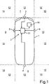
1 in schematischer Darstellung ein Kraftfahrzeug mit einem Multikamerasystem gemäß einer Ausführungsform der Erfindung; 1 a schematic representation of a motor vehicle with a multi-camera system according to an embodiment of the invention;

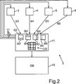
2 in schematischer Darstellung ein Blockschaltbild eines Multikamerasystems gemäß einer Ausführungsform der Erfindung; 2 a schematic diagram of a block diagram of a multi-camera system according to an embodiment of the invention;

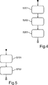
3 bis 6 Flussdiagramme eines Verfahrens gemäß einer Ausführungsform der Erfindung. 3 to 6 Flowcharts of a method according to an embodiment of the invention.

Ein in 1 dargestelltes Kraftfahrzeug 1 ist beispielsweise ein Personenkraftwagen. Das Kraftfahrzeug 1 hat ein Kamerasystem 2 mit beispielsweise vier Kameras 3, 4, 5, 6, welche an dem Kraftfahrzeug 1 derart verteilt angeordnet sind, dass die Kameras 3, 4, 5, 6 insgesamt die Umgebung um das Kraftfahrzeug 1 herum erfassen. Es wird somit die komplette Umgebung des Kraftfahrzeugs 1 und daher ein 360°-Bild erfasst. Die Kamera 3 ist dabei eine Frontkamera, welche im vorderen Bereich des Kraftfahrzeugs 1, beispielsweise hinter der Windschutzscheibe, angeordnet ist. Die Kamera 3 erfasst somit einen Umgebungsbereich 7 vor dem Kraftfahrzeug 1. Die zweite Kamera 4 ist eine Rückwärtskamera, welche im Heckbereich des Kraftfahrzeugs 1 angebracht ist, beispielsweise an einer Heckklappe oder hinter der Heckscheibe oder an einem hinteren Stoßfänger. Sie erfasst einen Umgebungsbereich 8 hinter dem Kraftfahrzeug 1. Die seitlichen Kameras 5, 6 können beispielsweise in die jeweiligen Außenspiegel integriert sein. Die dritte Kamera 5 erfasst dabei den Umgebungsbereich 9 links des Kraftfahrzeugs 1, während die vierte Kamera 6 einen Umgebungsbereich 10 auf der rechten Seite des Kraftfahrzeugs 1 erfasst.An in 1 illustrated motor vehicle 1 is for example a passenger car. The car 1 has a camera system 2 with for example four cameras 3 . 4 . 5 . 6 which on the motor vehicle 1 arranged so distributed that the cameras 3 . 4 . 5 . 6 Overall, the environment around the motor vehicle 1 capture around. It thus becomes the complete environment of the motor vehicle 1 and therefore captures a 360 ° image. The camera 3 is a front camera, which in the front of the vehicle 1 , For example, behind the windshield, is arranged. The camera 3 thus captures a surrounding area 7 in front of the motor vehicle 1 , The second camera 4 is a backward camera, which in the rear of the vehicle 1 is attached, for example, on a tailgate or behind the rear window or on a rear bumper. It captures a surrounding area 8th behind the motor vehicle 1 , The side cameras 5 . 6 For example, they can be integrated in the respective exterior mirrors. The third camera 5 captures the surrounding area 9 left of the motor vehicle 1 while the fourth camera 6 a surrounding area 10 on the right side of the motor vehicle 1 detected.

Die Anzahl sowie die Anordnung der Kameras 3, 4, 5, 6 sind in 1 lediglich beispielhaft dargestellt und können je nach Ausführungsform variieren.The number and arrangement of the cameras 3 . 4 . 5 . 6 are in 1 merely exemplified and may vary depending on the embodiment.

Die Kameras 3, 4, 5, 6 weisen einen relativ breiten Öffnungswinkel auf, der beispielsweise in einem Wertebereich von 160° bis 200° liegen kann. Die Kameras 3, 4, 5, 6 können beispielsweise sogenannte Fischaugenkameras sein. Sie können CCD-Kameras oder CMOS-Kameras sein.The cameras 3 . 4 . 5 . 6 have a relatively wide opening angle, which may for example be in a range of 160 ° to 200 °. The cameras 3 . 4 . 5 . 6 may be, for example, so-called fish eye cameras. They can be CCD cameras or CMOS cameras.

Die Kameras 3, 4, 5, 6 sind Video-Kameras, welche jeweils eine Vielzahl von Einzelbildern pro Sekunde bereitstellen können. Die Bilder werden dann an eine zentrale Rechen- und Steuereinrichtung 11 übermittelt, welche die Bilder aller Kameras 3, 4, 5, 6 verarbeitet. Die Aufnahme der Bilder durch alle Kameras 3, 4, 5, 6 erfolgt vorzugsweise zeitsynchron.The cameras 3 . 4 . 5 . 6 are video cameras, each of which can provide a variety of frames per second. The images are then sent to a central computer and control device 11 which transmits the images of all cameras 3 . 4 . 5 . 6 processed. The recording of pictures by all cameras 3 . 4 . 5 . 6 is preferably time-synchronized.

Die Kamera 3 erfasst also den Umgebungsbereich 7 vor dem Kraftfahrzeug 1. Die Kamera 3 hat somit einen Erfassungsbereich bzw. ein Sichtfeld 12, welcher bzw. welches den Umgebungsbereich 7 vor dem Kraftfahrzeug 1 abdeckt. Entsprechend weist auch die zweite Kamera 4 ein Sichtfeld 13 auf, welches den Umgebungsbereich 8 hinter dem Kraftfahrzeug 1 abdeckt. Entsprechende Sichtfelder der Kameras 5, 6 sind in 1 mit 14 bzw. 15 bezeichnet. Wie aus 1 hervorgeht, können sich die Sichtfelder der Kameras 3, 4, 5, 6 paarweise und bereichsweise gegenseitig überlappen. Und zwar können sich die Sichtfelder 12 und 14 der Kameras 3, 5, die Sichtfelder 12 und 15 der Kameras 3, 6, wie auch die Sichtfelder 13 und 14 der Kameras 4, 5 sowie die Sichtfelder 13 und 15 der Kameras 4, 6 gegenseitig überlappen.The camera 3 captures the surrounding area 7 in front of the motor vehicle 1 , The camera 3 thus has a detection area or a field of view 12 , which or which the surrounding area 7 in front of the motor vehicle 1 covers. Accordingly, also the second camera 4 a field of vision 13 on which the surrounding area 8th behind the motor vehicle 1 covers. Corresponding fields of view of the cameras 5 . 6 are in 1 With 14 respectively. 15 designated. How out 1 As can be seen, the fields of view of the cameras can 3 . 4 . 5 . 6 overlap each other in pairs and areas. And although the fields of view can 12 and 14 the cameras 3 . 5 , the fields of view 12 and 15 the cameras 3 . 6 as well as the fields of view 13 and 14 the cameras 4 . 5 as well as the fields of view 13 and 15 the cameras 4 . 6 overlap each other.

Die Rechen- und Steuereinrichtung 11 empfängt die Bilder aller Kameras 3, 4, 5, 6 und verarbeitet sie. Die Rechen- und Steuereinrichtung 11 berechnet aus den Videos aller Kameras 3, 4, 5, 6 in Echtzeit eine Gesamtdarstellung, welche eine Draufsicht auf das Kraftfahrzeug 1 und seine Umgebung 7, 8, 9, 10 aus einer Vogelperspektive zeigt. Bezogen auf die Einzelbilder der Kameras 3, 4, 5, 6 erzeugt die Rechen- und Steuereinrichtung 11 aus diesen Einzelbildern aller Kameras 3, 4, 5, 6 ein Gesamtbild, welches eine solche Draufsicht auf das Kraftfahrzeug 1 und seine Umgebung zeigt. Werden nun aus den gesamten Sequenzen von Einzelbildern der Kameras 3, 4, 5, 6 solche Gesamtbilder berechnet, so ergibt sich eine zeitliche Sequenz von Gesamtbildern, also ein Gesamtvideo. Dieses Gesamtvideo wird als Gesamtdarstellung in Echtzeit auf einem Display 16 im Kraftfahrzeug 1 dargestellt. Das Display 16 stellt dabei eine optische Anzeigeeinrichtung dar.The computing and control device 11 receives the pictures of all cameras 3 . 4 . 5 . 6 and process them. The computing and control device 11 calculated from the videos of all cameras 3 . 4 . 5 . 6 in real time an overall view, which is a top view of the motor vehicle 1 and its surroundings 7 . 8th . 9 . 10 from a bird's eye view. Related to the frames of the cameras 3 . 4 . 5 . 6 generates the computing and control device 11 from these frames of all cameras 3 . 4 . 5 . 6 an overall picture, which is such a plan view of the motor vehicle 1 and its surroundings shows. Now become from the entire sequences of individual images of the cameras 3 . 4 . 5 . 6 Computes such overall images, so results in a temporal sequence of overall images, so an overall video. This overall video is displayed as an overall representation in real time on a display 16 in the motor vehicle 1 shown. the display 16 represents an optical display device.

In 2 ist ein Blockdiagramm des Kamerasystems 2 dargestellt. Wie bereits ausgeführt, liefern die Kameras 3, 4, 5, 6 jeweilige Bilder B3, B4, B5, B6, aus denen eine Gesamtdarstellung GB erzeugt wird. Obwohl nachfolgend lediglich von Einzelbildern B3, B4, B5, B6 gesprochen wird, ist es selbstverständlich, dass die Kameras 3, 4, 5, 6 jeweils ein ganzes Video und somit eine zeitliche Sequenz von Bildern liefern.In 2 is a block diagram of the camera system 2 shown. As already stated, the cameras deliver 3 . 4 . 5 . 6 respective images B3, B4, B5, B6, from which an overall representation GB is generated. Although hereinafter only single frames B3, B4, B5, B6 spoken, it is understood that the cameras 3 . 4 . 5 . 6 each provide a whole video and thus a temporal sequence of images.

Aus gleichzeitig erfassten Bildern B3, B4, B5, B6 der Kameras 3, 4, 5, 6 erzeugt die Rechen- und Steuereinrichtung 11 die Gesamtdarstellung GB, welche eine Draufsicht auf das Kraftfahrzeug 1 und die Umgebung um das Kraftfahrzeug 1 herum zeigt. Dazu wird aus jedem Bild B3, B4, B5, B6 jeweils ein Bildbereich B3', B4', B5', B6' verwendet, nämlich derjenige Bildbereich, welcher den jeweiligen Umgebungsbereich 7, 8, 9, 10 bis zu einer vorbestimmten Entfernung vom Kraftfahrzeug 1 zeigt. Diese Bildbereiche B3', B4', B5', B6' der Bilder B3, B4, B5, B6 werden dann zu einem Gesamtbild bzw. einer Gesamtdarstellung GB zusammengefasst und dahingehend verarbeitet, dass der Eindruck entsteht, als würde die Gesamtdarstellung GB die jeweiligen Umgebungsbereiche 7, 8, 9, 10 aus einer Vogelperspektive zeigen. Diese Gesamtdarstellung GB wird dann auf dem Display 16 in Echtzeit angezeigt. From simultaneously acquired images B3, B4, B5, B6 of the cameras 3 . 4 . 5 . 6 generates the computing and control device 11 the overall view GB, which is a plan view of the motor vehicle 1 and the environment around the motor vehicle 1 shows around. For this purpose, an image area B3 ', B4', B5 ', B6' is used in each case from each image B3, B4, B5, B6, namely that image area which contains the respective surrounding area 7 . 8th . 9 . 10 up to a predetermined distance from the motor vehicle 1 shows. These image areas B3 ', B4', B5 ', B6' of the images B3, B4, B5, B6 are then combined into an overall image GB and processed to the effect that the overall representation GB would be the respective surrounding areas 7 . 8th . 9 . 10 show from a bird's eye view. This overall representation GB will then be on display 16 displayed in real time.

Beim Erzeugen der Gesamtdarstellung GB werden die jeweiligen Parameterwerte zumindest eines Bildparameters der Bildbereiche B3', B4', B5', B6' aneinander angeglichen. Im Ausführungsbeispiel werden einerseits die jeweiligen Helligkeitswerte der Bildbereiche B3', B4', B5', B6' aneinander angeglichen, nämlich die jeweiligen Medianwerte der Helligkeit (die jeweiligen Helligkeitsmedianwerte). Andererseits werden auch die Weißabgleichswerte der Bildbereiche B3', B4', B5', B6' aneinander angeglichen. Das Angleichen der Parameterwerte der Bildbereiche B3', B4', B5', B6' erfolgt dabei in zwei separaten Stufen: Zunächst erfolgt eine erste grobe Anpassung der Parameterwerte durch Ansteuerung der Kameras 3, 4, 5, 6 mittels der Rechen- und Steuereinrichtung 11, wie dies in 2 mit Steuerleitungen 17 schematisch angedeutet ist. Zum groben Anpassen der Parameterwerte wird dabei zumindest ein Betriebsparameter der Kameras 3, 4, 5, 6 gesteuert, nämlich im Falle der Anpassung der Helligkeitswerte beispielsweise die jeweiligen Belichtungszeiten und/oder Verstärkungsfaktoren der Kameras 3, 4, 5, 6. Im Falle der Anpassung der Weißabgleichswerte erfolgt eine Steuerung des internen Weißabgleichs der Kameras 3, 4, 5, 6. In einer zweiten Stufe werden die Parameterwerte der Bildbereiche B3', B4', B5', B6' (die Helligkeitswerte und/oder die Weißabgleichswerte) rechentechnisch mittels der Rechen- und Steuereinrichtung 11 entsprechend einem vorbestimmten Bildverarbeitungsalgorithmus fein justiert und auf einen Sollwert eingestellt. Während die erste Stufe des Angleichens somit kameraintern durchgeführt wird, erfolgt die Feinjustierung gemäß der zweiten Stufe außerhalb der Kameras 3, 4, 5, 6 und somit kameraextern alleine mittels Bildverarbeitung der Bildbereiche B3', B4', B5', B6'.When generating the overall representation GB, the respective parameter values of at least one image parameter of the image regions B3 ', B4', B5 ', B6' are matched to one another. In the exemplary embodiment, on the one hand, the respective brightness values of the image areas B3 ', B4', B5 ', B6' are matched to one another, namely the respective median values of the brightness (the respective brightness median values). On the other hand, the white balance values of the image areas B3 ', B4', B5 ', B6' are also matched to each other. The adjustment of the parameter values of the image areas B3 ', B4', B5 ', B6' takes place in two separate stages: First, a first coarse adaptation of the parameter values takes place by controlling the cameras 3 . 4 . 5 . 6 by means of the computing and control device 11 like this in 2 with control lines 17 is indicated schematically. For coarse adjustment of the parameter values is at least one operating parameter of the cameras 3 . 4 . 5 . 6 controlled, namely in the case of adjustment of the brightness values, for example, the respective exposure times and / or gain factors of the cameras 3 . 4 . 5 . 6 , In the case of adjustment of the white balance values, the internal white balance of the cameras is controlled 3 . 4 . 5 . 6 , In a second stage, the parameter values of the image areas B3 ', B4', B5 ', B6' (the brightness values and / or the white balance values) are computed by the computing and control device 11 finely adjusted in accordance with a predetermined image processing algorithm and set to a target value. Thus, while the first stage of equalization is performed in-camera, fine adjustment according to the second stage is done outside the cameras 3 . 4 . 5 . 6 and thus camera-external alone by means of image processing of the image areas B3 ', B4', B5 ', B6'.

Obwohl sich die nachfolgende Beschreibung auf die Anpassung von Helligkeitswerten der Bildbereiche B3', B4', B5', B6' bezieht, können in gleicher Weise auch die Weißabgleichswerte der Bildbereiche B3', B4', B5', B6' aneinander angeglichen werden.Although the following description refers to the adaptation of brightness values of the image areas B3 ', B4', B5 ', B6', the white balance values of the image areas B3 ', B4', B5 ', B6' can be matched to one another in the same way.

In den 3 bis 6 sind nun Flussdiagramme eines Verfahrens gemäß einer Ausführungsform der Erfindung dargestellt. 3 zeigt dabei eine Hauptschleife des Verfahrens, welche nach Aktivieren des so genannten „Topview”-Betriebsmodus des Kamerasystems 2 so lange wiederholt wird, bis dieser Betriebsmodus wieder deaktiviert wird. Das Aktivieren des „Topview”-Betriebsmodus erfolgt in einem ersten Schritt S1, woraufhin das Verfahren zu einem zweiten Schritt S2 übergeht. Im Schritt S2 empfängt die Rechen- und Steuereinrichtung 11 die Bilder B3, B4, B5, B6 und schneidet die Bildbereiche B3', B4', B5', B6' aus. Im Rahmen des Schrittes S2 werden auch weitere Unterschritte durchgeführt, welche anhand des Flussdiagramms gemäß 4 näher erläutert werden. In einem Schritt S201 empfängt die Rechen- und Steuereinrichtung 11 die Bilddaten und speichert die Bildbereiche B3', B4', B5', B6'.In the 3 to 6 Now, flowcharts of a method according to an embodiment of the invention are shown. 3 shows a main loop of the process, which after activating the so-called "Topview" mode of operation of the camera system 2 is repeated until this mode of operation is deactivated again. The activation of the "topview" operating mode takes place in a first step S1, whereupon the method proceeds to a second step S2. In step S2, the computing and control device receives 11 the images B3, B4, B5, B6 and cuts out the image areas B3 ', B4', B5 ', B6' from. As part of step S2, further sub-steps are carried out, which are based on the flowchart in accordance with 4 be explained in more detail. In a step S201, the computing and control device receives 11 the image data and stores the image areas B3 ', B4', B5 ', B6'.

In einem weiteren Schritt S202 berechnet die Rechen- und Steuereinrichtung 11 die jeweiligen Helligkeitsmedianwerte: Ymed_A für die Kamera 3, Ymed_B für die Kamera 4, Ymed_C für die Kamera 5 und Ymed_D für die Kamera 6, sowie die jeweilige Varianz der Helligkeitswerte aller Bildbereiche B3', B4', B5', B6': Yvar_A für die Kamera 3, Yvar_B für die Kamera 4, Yvar_C für die Kamera 5 und Yvar_D für die Kamera 6. Dies bedeutet, dass für jeden Bildbereich B3', B4', B5', B6' jeweils der Helligkeitsmedianwert Ymed_A, Ymed_B, Ymed_C und Ymed_D (Y-Medianwert im YUV-Farbraum) sowie die Varianz der Helligkeitswerte Yvar_A, Yvar_B, Yvar_C und Yvar_D (Varianz der Y-Werte) berechnet werden.In a further step S202 the computing and control device calculates 11 the respective brightness median values: Ymed_A for the camera 3 , Ymed_B for the camera 4 , Ymed_C for the camera 5 and Ymed_D for the camera 6 , as well as the respective variance of the brightness values of all image areas B3 ', B4', B5 ', B6': Yvar_A for the camera 3 , Yvar_B for the camera 4 , Yvar_C for the camera 5 and Yvar_D for the camera 6 , This means that the brightness median values Ymed_A, Ymed_B, Ymed_C and Ymed_D (Y median value in the YUV color space) for each image area B3 ', B4', B5 ', B6' and the variance of the brightness values Yvar_A, Yvar_B, Yvar_C and Yvar_D ( Variance of Y values).

In einem weiteren Schritt S203 berechnet die Rechen- und Steuereinrichtung 11 einen Gesamtmedianwert Ymed_Topview aus den Helligkeitsmedianwerten Ymed_A, Ymed_B, Ymed_C und Ymed_D der Bildbereiche B3', B4', B5', B6'. Dieser Gesamtmedianwert Ymed_Topview wird dann als Sollwert für die Anpassung der Helligkeitsmedianwerte Ymed_A, Ymed_B, Ymed_C und Ymed_D der Bildbereiche B3', B4', B5', B6' verwendet. Dieser Sollwert wird abgespeichert. Dies ist eine versatzresistente Angabe der mittleren Helligkeit des gesamten Draufsicht-Bilds und wird bei der Bestimmung verwendet, wie die Unterschiede zwischen den jeweiligen Kameramedianwerten Ymed_A, Ymed_B, Ymed_C und Ymed_D adressiert werden.In a further step S203, the computing and control device calculates 11 a total median value Ymed_Topview from the brightness median values Ymed_A, Ymed_B, Ymed_C and Ymed_D of the image areas B3 ', B4', B5 ', B6'. This total median value Ymed_Topview is then used as a setpoint for adjusting the brightness median values Ymed_A, Ymed_B, Ymed_C and Ymed_D of the image areas B3 ', B4', B5 ', B6'. This setpoint is stored. This is an offset-resistant indication of the average brightness of the entire top view image and is used in determining how to address the differences between the respective camera medians Ymed_A, Ymed_B, Ymed_C, and Ymed_D.

Mit erneutem Bezug auf 3 wird in einem Schritt S3 überprüft, ob das grobe Anpassen der jeweiligen Helligkeitsmedianwerte Ymed_A, Ymed_B, Ymed_C und Ymed_D der Bildbereiche B3', B4', B5', B6' erforderlich ist oder nicht. Dabei überprüft die Rechen- und Steuereinrichtung 11, ob die aktuellen Helligkeitsmedianwerte Ymed_A, Ymed_B, Ymed_C und Ymed_D der Bildbereiche B3', B4', B5', B6' innerhalb eines vorgegebenen Wertebereichs um den Sollwert Ymed_Topview liegen oder nicht. Ist ein grobes Angleichen der Helligkeitsmedianwerte Ymed_A, Ymed_B, Ymed_C und Ymed_D erforderlich, so geht das Verfahren zu einem weiteren Schritt S4 über, in welchem eine Nachregelung der Betriebsparameter der Kameras 3, 4, 5, 6 mittels der Rechen- und Steuereinrichtung 11 erfolgt, nämlich eine Nachregelung der jeweiligen Belichtungszeit und des jeweiligen Verstärkungsfaktors. Dieses grobe Anpassen der Helligkeitsmedianwerte Ymed_A, Ymed_B, Ymed_C und Ymed_D der Bildbereiche B3', B4', B5', B6' und somit die Beschränkung dieser Helligkeitsmedianwerte auf den vorgegebenen Wertebereich um den Sollwert Ymed_Topview erfolgt folglich kameraintern unter Ansteuerung der Kameras 3, 4, 5, 6 über die Steuerleitungen 17.With renewed reference to 3 a check is made in step S3 as to whether the coarse adjustment of the respective brightness median values Ymed_A, Ymed_B, Ymed_C and Ymed_D of the image areas B3 ', B4', B5 ', B6' is checked. is required or not. The computing and control device checks 11 whether the current brightness median values Ymed_A, Ymed_B, Ymed_C and Ymed_D of the image areas B3 ', B4', B5 ', B6' lie within a predetermined value range around the setpoint value Ymed_Topview or not. If a coarse adjustment of the brightness median values Ymed_A, Ymed_B, Ymed_C and Ymed_D is required, the method proceeds to a further step S4, in which a readjustment of the operating parameters of the cameras 3 . 4 . 5 . 6 by means of the computing and control device 11 takes place, namely a readjustment of the respective exposure time and the respective gain factor. This coarse adjustment of the brightness median values Ymed_A, Ymed_B, Ymed_C and Ymed_D of the image areas B3 ', B4', B5 ', B6' and thus the restriction of these brightness median values to the predetermined value range around the setpoint Ymed_Topview thus takes place in-camera under the control of the cameras 3 . 4 . 5 . 6 over the control lines 17 ,

Dieser Ansatz dient zur Vermeidung übermäßiger Änderung der Kameras 3, 4, 5, 6 und der Ansicht im Allgemeinen. Es kann auch wie folgt implementiert werden: Falls alle Medianwerte Ymed_A, Ymed_B, Ymed_C und Ymed_D innerhalb eines vorgegebenen Wertebereichs um den Sollwert Ymed_Topview liegen, d. h. innerhalb +/–TH1 um Ymed_Topview (wobei TH1 beispielsweise auf 30 eingestellt ist) oder falls mindestens einer der Medianwerte Ymed_A, Ymed_B, Ymed_C, Ymed_D außerhalb eines größeren Wertebereichs liegt, d. h. außerhalb +/–THL um Ymed_Topview (wobei THL größer als TH1 und beispielsweise auf 100 eingestellt ist), dann wird vorzugsweise keine Anpassung an den Kameras 3, 4, 5, 6 durchgeführt. Ansonsten wird eine Aktion an den Kameras 3, 4, 5, 6 benötigt.This approach helps avoid excessive camera changes 3 . 4 . 5 . 6 and the view in general. It can also be implemented as follows: If all median values Ymed_A, Ymed_B, Ymed_C and Ymed_D are within a specified value range around the Ymed_Topview setpoint, ie within +/- TH1 by Ymed_Topview (where TH1 is set to 30, for example) or if at least one of the If median values Ymed_A, Ymed_B, Ymed_C, Ymed_D are outside a larger value range, ie outside +/- THL by Ymed_Topview (where THL is greater than TH1 and set to 100, for example), then preferably no adaptation is made to the cameras 3 . 4 . 5 . 6 carried out. Otherwise there will be an action on the cameras 3 . 4 . 5 . 6 needed.

Der Schritt S4 beinhaltet dabei mehrere Unterschritte, welche Bezug nehmend auf 6 näher erläutert werden:
Das Ausführungsbeispiel gemäß 6 kann insbesondere bei einem ARM-Prozessor durchgeführt werden, welcher in die Rechen- und Steuereinrichtung 11 integriert sein kann. In einem Schritt S430 wird zunächst in Bezug auf die Kamera 3 überprüft, ob der Helligkeitsmedianwert Ymed_A des Bildbereichs B3' innerhalb oder außerhalb des vorgegebenen Wertebereichs TH1 um den Sollwert liegt. Wird eine Abweichung detektiert, geht das Verfahren zu einem weiteren Schritt S431 über, in welchem die erforderliche Veränderung der Belichtungszeit und/oder des Verstärkungsfaktors des Bildsensors der Kamera 3 berechnet wird, damit der Helligkeitsmedianwert des Bildbereichs B3' innerhalb des vorgegebenen Wertebereichs TH1 liegt. Bei diesem Schritt S431 greift die Rechen- und Steuereinrichtung 11 auch auf die Daten aus einem Datenblatt der Kamera 3 zu.
Step S4 includes several sub-steps, which refer to FIG 6 be explained in more detail:
The embodiment according to 6 can be performed in particular in an ARM processor, which in the computing and control device 11 can be integrated. In a step S430, first with respect to the camera 3 checks whether the brightness median value Ymed_A of the image area B3 'lies within the specified value range TH1 or within the setpoint. If a deviation is detected, the method proceeds to a further step S431, in which the required change in the exposure time and / or the amplification factor of the image sensor of the camera 3 is calculated so that the brightness median value of the image area B3 'is within the predetermined value range TH1. In this step S431, the computing and control device accesses 11 also on the data from a data sheet of the camera 3 to.

Die Register für die Belichtungsziele auf dem OV10630-Bildsensor sind: 0xC46A, 0xC46D, 0xC464, 0xC465. Vorzugsweise werden zwei Schrittweiten zur Modifizierung der Verstärkung und/oder der Belichtungsziele definiert: eine kleine Schrittweite (z. B. 0x08) sowie eine große Schrittweite (z. B. 0x10). Folgendes Szenario kann vorgesehen sein: Wenn sich der Medianwert Ymed_A von dem Sollwert Ymed_Topview um mehr als die genannte Schwelle THL unterscheidet, wird keine Veränderung vorgenommen. Aber, wenn die Differenz (Ymed_A – Ymed_Topview) größer als die Schwelle TH1 und kleiner als THL ist, dann wird die Änderung des Verstärkungsfaktors und/oder der Belichtung auf die negative große Schrittweite eingestellt. In Analogie, wenn die Differenz (Ymed_Topview – Ymed_A) größer als TH1 ist, wird die Änderung des Verstärkungsfaktors und/oder der Belichtung auf die positive große Schrittweite eingestellt. Wenn jedoch die Differenz (Ymed_A – Ymed_Topview) oder (Ymed_Topview – Ymed_A) größer ist als eine kleinere Schwelle TH2 aber kleiner als die Schwelle TH1 ist, wird die Änderung des Verstärkungsfaktors und/oder der Belichtung auf die negative respektive positive kleine Schrittweite eingestellt. Somit kann die Anpassung an den Kameras 3, 4, 5, 6 schrittweise ausgeführt werden.The exposure target tabs on the OV10630 image sensor are: 0xC46A, 0xC46D, 0xC464, 0xC465. Preferably, two increments are defined to modify the gain and / or the exposure targets: a small step size (eg 0x08) and a large step size (eg 0x10). The following scenario can be provided: If the median value Ymed_A differs from the setpoint value Ymed_Topview by more than said threshold THL, no change is made. But if the difference (Ymed_A - Ymed_Topview) is greater than the threshold TH1 and less than THL, then the change in the gain and / or the exposure is set to the negative large step size. By analogy, if the difference (Ymed_Topview - Ymed_A) is greater than TH1, the change in the gain and / or the exposure is set to the positive large step size. However, if the difference (Ymed_A-Ymed_Topview) or (Ymed_Topview-Ymed_A) is greater than a smaller threshold TH2 but less than the threshold TH1, the change in the gain and / or the exposure is set to the negative or positive small step size. Thus, the adaptation to the cameras 3 . 4 . 5 . 6 be executed step by step.

Im Anschluss wird dann in einem Schritt S432 überprüft, ob die aktuelle Änderung der Belichtungszeit und/oder des Verstärkungsfaktors der Kamera 3 eine dritte Änderung in die gleiche Richtung ist oder nicht. Ist dies nicht der Fall, geht das Verfahren zu einem weiteren Schritt S433 über, in welchem über den genannten ARM-Prozessor Steuersignale an die Kamera 3 abgegeben werden, welche die zuvor berechnete Änderung der Belichtungszeit und/oder des Verstärkungsfaktors bewirken. Auch hier wird auf das Datenblatt 18 der Kamera 3 zugegriffen. Dies bedeutet: Wenn es der dritte Schritt in der gleichen Richtung ist, werden keine Änderungen vorgenommen. Wenn dies eine Änderung in der anderen Richtung ist oder weniger als dritter Schritt in einer bestimmten Richtung ist, dann wird die Veränderung an der Kamera vorgenommen.Subsequently, it is then checked in a step S432 whether the current change in the exposure time and / or the amplification factor of the camera 3 a third change in the same direction or not. If this is not the case, the method proceeds to a further step S433, in which via the said ARM processor control signals to the camera 3 are emitted, which cause the previously calculated change in the exposure time and / or the gain factor. Again, the data sheet 18 the camera 3 accessed. This means that if it is the third step in the same direction, no changes will be made. If this is a change in the other direction or less than a third step in a particular direction, then the change is made to the camera.

Wird in Schritt S432 jedoch festgestellt, dass die aktuelle Änderung bereits eine dritte Änderung in die gleiche Richtung darstellt, geht das Verfahren zu einem weiteren Schritt S440. Auch wenn gemäß Schritt S430 keine Ansteuerung der Kamera 3 erforderlich ist, geht das Verfahren zum Schritt S440 über. Auch nach Durchführen des Schritts S433 geht das Verfahren zum Schritt S440 über.However, if it is determined in step S432 that the current change already represents a third change in the same direction, the process goes to a further step S440. Even if, according to step S430, no driving of the camera 3 is required, the process proceeds to step S440. Even after performing step S433, the process proceeds to step S440.

Die Schritte S440, S441, S442 und S443 entsprechen den Schritten S430, S431, S432 und S433 und beziehen sich auf die zweite Kamera 4. Im Schritt S440 wird also überprüft, ob der Helligkeitsmedianwert des Bildbereichs B4' außerhalb des vorgegebenen Wertebereichs um den Sollwert liegt. Ist dies der Fall, wird gemäß Schritt S441 die erforderliche Veränderung der Belichtungszeit und/oder des Verstärkungsfaktors der Kamera 4 berechnet. Ist diese Änderung eine dritte Änderung in die gleiche Richtung, wird die Anpassung gemäß Schritt S442 unterbrochen. Ist dies nicht der Fall, erfolgt gemäß Schritt S443 eine Kommunikation mit der Kamera 4 und somit die Anpassung der Belichtungszeit und/oder des Verstärkungsfaktors. Steps S440, S441, S442, and S443 correspond to steps S430, S431, S432, and S433, and refer to the second camera 4 , In step S440, it is thus checked whether the brightness median value of the image area B4 'lies outside the predetermined value range around the desired value. If so, the required change in exposure time and / or gain of the camera is made in step S441 4 calculated. If this change is a third change in the same direction, the adjustment in step S442 is interrupted. If this is not the case, a communication with the camera takes place in accordance with step S443 4 and thus the adaptation of the exposure time and / or the amplification factor.

Auch die Schritte S450, S451, S452, S453 entsprechen den Schritten S430, S431, S432, S433, betreffen jedoch die Kamera 5. Entsprechendes gilt auch für die Schritte S460, S461, S462 und S463, welche jedoch die vierte Kamera 6 betreffen.Also, the steps S450, S451, S452, S453 correspond to the steps S430, S431, S432, S433, but concern the camera 5 , The same applies to the steps S460, S461, S462 and S463, which, however, the fourth camera 6 affect.

Mit erneutem Bezug auf 3 geht das Verfahren nach Abschluss des Schritts S4 zu einem weiteren Schritt S5 über, in welchem ein Abklingen (settle down) des Systems erfolgt. Das System wird n Einzelbilder zum Abklingen abwarten, bevor eine weitere Änderung vorgenommen wird. Der Standardwert für n kann zum Beispiel 3 betragen. Das Verfahren kehrt dann wieder zum Schritt S2 zurück, in welchem neue Bilder B3, B4, B5, B6 erfasst werden und somit neue Bilddaten vorliegen.With renewed reference to 3 After completion of step S4, the method proceeds to a further step S5, in which a settle down of the system takes place. The system will wait n frames to decay before making another change. The default value for n may be 3, for example. The process then returns to step S2, in which new images B3, B4, B5, B6 are acquired and thus new image data is present.

Es wird noch einmal gemäß Schritt S3 anhand der neuen Bilddaten überprüft, ob eine zusätzliche Ansteuerung der Kameras 3, 4, 5, 6 erforderlich ist oder nicht. Ist dies nicht mehr erforderlich und liegen alle Helligkeitsmedianwerte Ymed der Bildbereiche B3', B4', B5', B6' innerhalb des vorgegebenen Wertebereichs um den Sollwert, geht das Verfahren zu einem weiteren Schritt S6 über, in welchem überprüft wird, ob eine kameraexterne Feinjustierung der Helligkeitsmedianwerte auf den Sollwert erforderlich ist oder nicht. Hierbei kann die Rechen- und Steuereinrichtung 11 überprüfen, ob die Helligkeitsmedianwerte Ymed innerhalb eines engeren und somit kleineren Wertebereichs um den Sollwert liegen und somit angenommen werden kann, dass diese Medianwerte im Wesentlichen gleich dem Sollwert sind. Ist keine weitere Feinjustierung mittels Bildverarbeitung erforderlich, kehrt das Verfahren zum Schritt S2 zurück. Ist die Feinjustierung notwendig, wird sie in einem Schritt S7 durchgeführt.It is again checked according to step S3 using the new image data, whether an additional control of the cameras 3 . 4 . 5 . 6 is required or not. If this is no longer necessary and all brightness median values Ymed of the image areas B3 ', B4', B5 ', B6' are within the predetermined value range around the setpoint value, the method proceeds to a further step S6, in which it is checked whether a camera-external fine adjustment the brightness median values to the setpoint is required or not. Here, the computing and control device 11 check whether the brightness median values Ymed lie within a narrower and thus smaller range of values around the setpoint and thus can assume that these median values are substantially equal to the setpoint. If no further fine adjustment by means of image processing is required, the method returns to step S2. If the fine adjustment is necessary, it is performed in a step S7.

Dies erfolgt, um festzustellen, ob ein Nachverarbeitungsschritt erforderlich ist. Es wird in diesem Fall nichts an den Kameras 3, 4, 5, 6 selbst vorgenommen, sondern die Verarbeitung wird an den Video-Ausgangsdaten vorgenommen, und die Y-Werte werden entsprechend skaliert. Dies verhindert eine übermäßige Modifikation der Kameras 3, 4, 5, 6 und der Sicht im Allgemeinen. Dies kann wie folgt durchgeführt werden: Wenn alle Mediane Ymed_A, Ymed_B, Ymed_C und Ymed_D innerhalb eines Wertebereichs +/–TH3 um Ymed_Topview liegen, wobei TH3 < TH2 <TH1 und beispielsweise TH3 = 5, dann ist die Nachbearbeitung der Video-Daten nicht erforderlich. Andernfalls wird eine Nachbearbeitung vorgenommen.This is done to determine if a post-processing step is required. In this case, there will be nothing wrong with the cameras 3 . 4 . 5 . 6 but the processing is done on the video output data and the Y values are scaled accordingly. This prevents excessive modification of the cameras 3 . 4 . 5 . 6 and the view in general. This can be done as follows: If all medians Ymed_A, Ymed_B, Ymed_C and Ymed_D lie within a range of values +/- TH3 by Ymed_Topview, where TH3 <TH2 <TH1 and TH3 = 5, for example, then post-processing of the video data is not required , Otherwise, a post-processing will be made.

Der Schritt S7 beinhaltet zwei Unterschritte, welche in 5 abgebildet sind. Gemäß Schritt S701 wird für jede Kamera 3, 4, 5, 6 zunächst ein Skalierungsfaktor berechnet, mit welchem die Y-Werte (jedes Bildpunktes) und somit die Helligkeitswerte des jeweiligen Bildbereichs B3', B4', B5', B6' multipliziert bzw. skaliert werden sollen. In dem nachfolgenden Schritt S702 werden dann die Y-Werte der Bildpunkte der Bildbereiche B3', B4', B5', B6' mit dem jeweiligen Skalierungsfaktor multipliziert.Step S7 includes two sub-steps, which in 5 are shown. According to step S701, for each camera 3 . 4 . 5 . 6 First, a scaling factor is calculated with which the Y values (of each pixel) and thus the brightness values of the respective image region B3 ', B4', B5 ', B6' are to be multiplied or scaled. In the subsequent step S702, the Y values of the pixels of the image areas B3 ', B4', B5 ', B6' are then multiplied by the respective scaling factor.

Es existieren jedoch zwei mögliche Wege, um den Kamera-Alphawert zu berechnen, und jeder von diesen kann genutzt werden. Gemäß dem ersten kann die Berechnung folgendermaßen durchgeführt werden, wobei αA αB αC αD die jeweiligen Alphawerte der Kameras 3, 4, 5, 6 bezeichnen:
für die Kamera 3: αA = basic_stepsize·|Ymed_A – Ymed_Topview|;
für die Kamera 4: αB = basic_stepsize·|Ymed_B – Ymed_Topview|;
für die Kamera 5: αC = basic_stepsize·|Ymed_C – Ymed_Topview|; und
für die Kamera 6: αD = basic_stepsize·|Ymed_D – Ymed_Topview|.
However, there are two possible ways to calculate the camera alpha value, and any of these can be used. According to the first, the calculation may be performed as follows, where α A α B α C α D are the respective alpha values of the cameras 3 . 4 . 5 . 6 describe:
for the camera 3 : α A = basic_stepsize · | Ymed_A - Ymed_Topview |;
for the camera 4 : α B = basic_stepsize · | Ymed_B - Ymed_Topview |;
for the camera 5 : α C = basic_stepsize · | Ymed_C - Ymed_Topview |; and
for the camera 6 : α D = basic_stepsize · | Ymed_D - Ymed_Topview |.

Gemäß dem zweiten Weg kann die Berechnung folgendermaßen durchgeführt werden: αA = αB = αC = αD = basic_stepsize.According to the second way, the calculation can be performed as follows: α A = α B = α C = α D = basic_stepsize.

Der Standardwert des Parameters ”basic_stepsize” kann auf 0.5 eingestellt werden, jedoch kann dieser Wert auch variiert werden. Es kann ein beliebiger Wert zwischen 0 und 1 sein; je höher der Wert, desto größer ist die Skalierung.The default value of the "basic_stepsize" parameter can be set to 0.5, but this value can also be varied. It can be any value between 0 and 1; the higher the value, the larger the scale.

Der auf die Videodaten der Kameras 3, 4, 5, 6 anzuwendende Skalierungswert wird wie folgt berechnet:
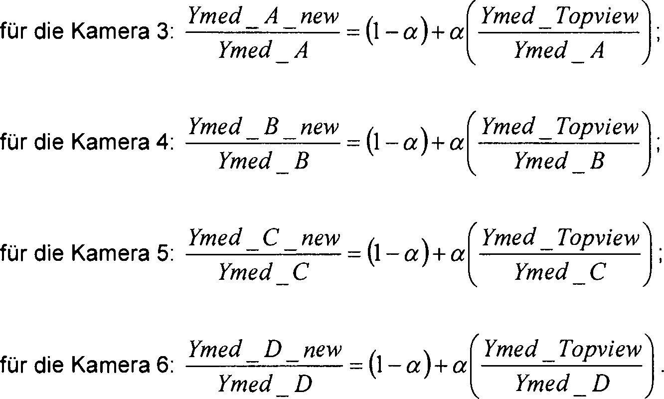
Figure DE102012024972A1_0002
The on the video data of the cameras 3 . 4 . 5 . 6 the scaling value to be applied is calculated as follows:
Figure DE102012024972A1_0002

Darüber hinaus ist es auch möglich, einen zusätzlichen Skalierungsfaktor von 0 bis 1 vorzusehen, der gemäß einer vom Benutzer bestimmten Helligkeitskonfiguration bestimmt werden kann.In addition, it is also possible to provide an additional scaling factor of 0 to 1, which can be determined according to a user-defined brightness configuration.

Gemäß Schritt S7 erfolgt also eine Feinjustierung und somit eine genaue Einstellung der Helligkeitsmedianwerte Ymed der Bildbereiche B3', B4', B5', B6' auf den zuvor berechneten Sollwert. Im Schritt S7 wird also ein Bildverarbeitungsalgorithmus durchgeführt, gemäß welchem – im vorliegenden Ausführungsbeispiel – die Y-Werte der Bildbereiche mit einem jeweiligen Skalierungsfaktor multipliziert werden. Diese Feinjustierung erfolgt außerhalb der Kameras 3, 4, 5, 6 mittels der Rechen- und Steuereinrichtung 11.Thus, according to step S7, a fine adjustment and thus an accurate adjustment of the brightness median values Ymed of the image regions B3 ', B4', B5 ', B6' to the previously calculated setpoint occurs. In step S7, therefore, an image processing algorithm is carried out, according to which-in the present exemplary embodiment-the Y values of the image regions are multiplied by a respective scaling factor. This fine adjustment takes place outside the cameras 3 . 4 . 5 . 6 by means of the computing and control device 11 ,

Optional kann auch vorgesehen sein, dass im Schritt S2 die Rechen- und Steuereinrichtung 11 überprüft, ob zumindest einer der Helligkeitsmedianwerte Ymed der Bildbereiche B3', B4', B5', B6' den genannten vorgegebenen Grenzwert THL überschreitet. Wird eine solche Überschreitung des Grenzwerts detektiert, kann auf das Angleichen der Helligkeitsmedianwerte Ymed aneinander zunächst für ein vorgegebenes Zeitintervall – beispielsweise für die Zeitdauer von einigen Bildern – verzichtet werden. Nach Ablauf dieser Zeitdauer kann die Rechen- und Steuereinrichtung 11 wieder die jeweiligen aktuellen Helligkeitsmedianwerte Ymed anhand der aktuellen Bilder B3, B4, B5, B6 berechnen.Optionally, it may also be provided that in step S2 the computing and control device 11 checks whether at least one of the brightness median values Ymed of the image areas B3 ', B4', B5 ', B6' exceeds said predetermined threshold value THL. If such exceeding of the limit value is detected, it is initially possible to dispense with equalizing the brightness median values Ymed to one another for a given time interval, for example for the duration of a few images. After this period of time, the computing and control device 11 again calculate the respective current brightness median values Ymed on the basis of the current images B3, B4, B5, B6.

ZITATE ENTHALTEN IN DER BESCHREIBUNG QUOTES INCLUDE IN THE DESCRIPTION

Diese Liste der vom Anmelder aufgeführten Dokumente wurde automatisiert erzeugt und ist ausschließlich zur besseren Information des Lesers aufgenommen. Die Liste ist nicht Bestandteil der deutschen Patent- bzw. Gebrauchsmusteranmeldung. Das DPMA übernimmt keinerlei Haftung für etwaige Fehler oder Auslassungen.This list of the documents listed by the applicant has been generated automatically and is included solely for the better information of the reader. The list is not part of the German patent or utility model application. The DPMA assumes no liability for any errors or omissions.

Zitierte PatentliteraturCited patent literature

  • US 2011/0156887 [0002] US 2011/0156887 [0002]
  • EP 2012271 A2 [0003, 0005] EP 2012271 A2 [0003, 0005]

Claims (12)

Verfahren zum Betreiben eines Multikamerasystems (2) eines Kraftfahrzeugs (1), bei welchem zumindest zwei Kameras (3, 4, 5, 6) jeweils Bilder (B3, B4, B5, B6) eines Umgebungsbereichs (7, 8, 9, 10) des Kraftfahrzeugs (1) bereitstellen und aus jeweils einem Bildbereich (B3', B4', B5', B6') der zumindest zwei Kameras (3, 4, 5, 6) eine Gesamtdarstellung (GB) mittels einer elektronischen Recheneinrichtung (11) erzeugt wird, wobei beim Erzeugen der Gesamtdarstellung (GB) jeweilige Parameterwerte zumindest eines Bildparameters der Bildbereiche (B3', B4', B5', B6') aneinander angeglichen und hierbei auf einen gemeinsamen Sollwert (Ymed_Topview) eingestellt werden, dadurch gekennzeichnet, dass das Angleichen der jeweiligen Parameterwerte der Bildbereiche (B3', B4', B5', B6') umfasst, dass zunächst durch Einstellen zumindest eines Betriebsparameters der jeweiligen Kamera (3, 4, 5, 6) die Parameterwerte auf einen vorgegebenen Wertebereich (TH1, TH2) um den Sollwert (Ymed_Topview) beschränkt werden und durch anschließendes Durchführen eines Bildverarbeitungsalgorithmus mittels der Recheneinrichtung (11) auf den Sollwert (Ymed_Topview) eingestellt werden.Method for operating a multi-camera system ( 2 ) of a motor vehicle ( 1 ), in which at least two cameras ( 3 . 4 . 5 . 6 ) each images (B3, B4, B5, B6) of a surrounding area ( 7 . 8th . 9 . 10 ) of the motor vehicle ( 1 ) and from each of an image area (B3 ', B4', B5 ', B6') of the at least two cameras ( 3 . 4 . 5 . 6 ) an overall representation (GB) by means of an electronic computing device ( 11 In generating the overall representation (GB), respective parameter values of at least one image parameter of the image regions (B3 ', B4', B5 ', B6') are matched to one another and adjusted to a common desired value (Ymed_Topview), characterized in that the matching of the respective parameter values of the image areas (B3 ', B4', B5 ', B6') comprises firstly by adjusting at least one operating parameter of the respective camera ( 3 . 4 . 5 . 6 ) the parameter values are limited to a predefined value range (TH1, TH2) by the desired value (Ymed_Topview) and by subsequent execution of an image processing algorithm by means of the computing device ( 11 ) to the setpoint (Ymed_Topview). Verfahren nach Anspruch 1, dadurch gekennzeichnet, dass der Sollwert (Ymed_Topview) für den zumindest einen Bildparameter der Bildbereiche (B3', B4', B5', B6') im Betrieb des Multikamerasystems (2) eingestellt wird.A method according to claim 1, characterized in that the setpoint value (Ymed_Topview) for the at least one image parameter of the image areas (B3 ', B4', B5 ', B6') during operation of the multi-camera system ( 2 ) is set. Verfahren nach Anspruch 1 oder 2, dadurch gekennzeichnet, dass der Sollwert (Ymed_Topview) auf einen Medianwert der vor dem Angleichen erfassten Parameterwerte der Bildbereiche (B3', B4', B5', B6') eingestellt wird.Method according to Claim 1 or 2, characterized in that the desired value (Ymed_Topview) is set to a median value of the parameter values of the image regions (B3 ', B4', B5 ', B6') acquired before the adjustment. Verfahren nach einem der vorhergehenden Ansprüche, dadurch gekennzeichnet, dass der Sollwert (Ymed_Topview) auf den vor dem Angleichen erfassten Parameterwert des Bildbereichs (B3', B4', B5', B6') einer der zumindest zwei Kameras (3, 4, 5, 6) eingestellt wird.Method according to one of the preceding claims, characterized in that the setpoint value (Ymed_Topview) relates to the parameter value of the image area (B3 ', B4', B5 ', B6') of one of the at least two cameras ( 3 . 4 . 5 . 6 ) is set. Verfahren nach einem der vorhergehenden Ansprüche, dadurch gekennzeichnet, dass die jeweiligen Werte einer Helligkeit der Bildbereiche (B3', B4', B5', B6') als Bildparameter, insbesondere die jeweiligen Medianwerte der Helligkeit der Bildbereiche (B3', B4', B5', B6'), aneinander angeglichen werden.Method according to one of the preceding claims, characterized in that the respective values of a brightness of the image areas (B3 ', B4', B5 ', B6') as image parameters, in particular the respective median values of the brightness of the image areas (B3 ', B4', B5 ', B6'), be aligned with each other. Verfahren nach Anspruch 5, dadurch gekennzeichnet, dass das Angleichen der Helligkeitswerte der Bildbereiche (B3', B4', B5', B6') umfasst, dass zunächst durch Einstellen einer jeweiligen Belichtungszeit und/oder eines jeweiligen Verstärkungsfaktors eines Bildsensors der Kameras (3, 4, 5, 6) die Helligkeitswerte der Bildbereiche (B3', B4', B5', B6') auf den vorgegebenen Wertebereich um den Sollwert beschränkt werden.Method according to claim 5, characterized in that the matching of the brightness values of the image areas (B3 ', B4', B5 ', B6') comprises firstly setting a respective exposure time and / or a respective amplification factor of an image sensor of the cameras (B3 ', B4', B5 ', B6'). 3 . 4 . 5 . 6 ) the brightness values of the image areas (B3 ', B4', B5 ', B6') are limited to the predetermined value range around the setpoint value. Verfahren nach einem der vorhergehenden Ansprüche, dadurch gekennzeichnet, dass die jeweiligen Werte eines Weißabgleichs der Bildbereiche (B3', B4', B5', B6') als Bildparameter aneinander angeglichen werden.Method according to one of the preceding claims, characterized in that the respective values of a white balance of the image areas (B3 ', B4', B5 ', B6') are matched to one another as image parameters. Verfahren nach Anspruch 7, dadurch gekennzeichnet, dass zum Beschränken der Weißabgleichswerte der Bildbereiche (B3', B4', B5', B6') auf den vorgegebenen Wertebereich ein interner Weißabgleich innerhalb der Kameras (3, 4, 5, 6) mittels jeweils einer internen Steuereinheit der Kameras (3, 4, 5, 6) durchgeführt wird.A method according to claim 7, characterized in that for limiting the white balance values of the image areas (B3 ', B4', B5 ', B6') to the predetermined value range, an internal white balance within the cameras ( 3 . 4 . 5 . 6 ) by means of an internal control unit of the cameras ( 3 . 4 . 5 . 6 ) is carried out. Verfahren nach einem der vorhergehenden Ansprüche, dadurch gekennzeichnet, dass falls einer der vor dem Angleichen erfassten Parameterwerte der Bildbereiche (B3', B4', B5', B6') einen vorbestimmten Grenzwert (THL) überschreitet, das Angleichen der jeweiligen Parameterwerte der Bildbereiche (B3', B4', B5', B6') unterbleibt.Method according to one of the preceding claims, characterized in that if one of the parameter values of the image areas (B3 ', B4', B5 ', B6') acquired before the matching exceeds a predetermined limit value (THL), the matching of the respective parameter values of the image areas ( B3 ', B4', B5 ', B6') is omitted. Verfahren nach einem der vorhergehenden Ansprüche, dadurch gekennzeichnet, dass als Gesamtdarstellung (GB) eine Draufsichtdarstellung erzeugt wird, welche eine Draufsicht auf das Kraftfahrzeug (1) und seine Umgebung (7, 8, 9, 10) zeigt.Method according to one of the preceding claims, characterized in that an overall view (GB) of a plan view is generated, which is a plan view of the motor vehicle ( 1 ) and its environment ( 7 . 8th . 9 . 10 ) shows. Multikamerasystem (2) für ein Kraftfahrzeug (1), umfassend zumindest zwei Kameras (3, 4, 5, 6) jeweils zum Bereitstellen von Bildern (B3, B4, B5, B6) eines Umgebungsbereichs (7, 8, 9, 10) des Kraftfahrzeugs (1), und umfassend eine elektronische Recheneinrichtung (11) zum Erzeugen einer Gesamtdarstellung (GB) aus jeweils einem Bildbereich (B3', B4', B5', B6') der zumindest zwei Kameras (3, 4, 5, 6), wobei das Multikamerasystem (2) dazu ausgebildet ist, beim Erzeugen der Gesamtdarstellung (GB) jeweilige Parameterwerte zumindest eines Bildparameters der Bildbereiche (B3', B4', B5', B6') der zumindest zwei Kameras (3, 4, 5, 6) aneinander anzugleichen und hierbei auf einen Sollwert einzustellen, dadurch gekennzeichnet, dass das Multikamerasystem (2) eine Steuereinrichtung (11) aufweist, welche zum Angleichen der jeweiligen Parameterwerte der Bildbereiche (B3', B4', B5', B6') zunächst durch Einstellen zumindest eines Betriebsparameters der jeweiligen Kamera (3, 4, 5, 6) die Parameterwerte auf einen vorgegebenen Wertebereich um den Sollwert beschränkt, wobei die Recheneinrichtung (11) dazu ausgelegt ist, nach Beschränken der Parameterwerte durch anschließendes Durchführen eines Bildverarbeitungsalgorithmus die Parameterwerte auf den Sollwert einzustellen.Multi-camera system ( 2 ) for a motor vehicle ( 1 ) comprising at least two cameras ( 3 . 4 . 5 . 6 ) each for providing images (B3, B4, B5, B6) of a surrounding area ( 7 . 8th . 9 . 10 ) of the motor vehicle ( 1 ), and comprising an electronic computing device ( 11 ) for generating an overall representation (GB) from in each case one image region (B3 ', B4', B5 ', B6') of the at least two cameras (FIG. 3 . 4 . 5 . 6 ), whereby the multi-camera system ( 2 ) is designed to generate, when generating the overall representation (GB), respective parameter values of at least one image parameter of the image regions (B3 ', B4', B5 ', B6') of the at least two cameras (FIG. 3 . 4 . 5 . 6 ) and adjust to a setpoint, characterized in that the multi-camera system ( 2 ) a control device ( 11 ), which for matching the respective Parameter values of the image areas (B3 ', B4', B5 ', B6') first by setting at least one operating parameter of the respective camera ( 3 . 4 . 5 . 6 ) limits the parameter values to a predetermined value range around the setpoint value, wherein the computing device ( 11 ) is configured to set the parameter values to the setpoint after restricting the parameter values by subsequently performing an image processing algorithm. Kraftfahrzeug (1) mit einem Multikamerasystem (2) nach Anspruch 11.Motor vehicle ( 1 ) with a multi-camera system ( 2 ) according to claim 11.
DE201210024972 2012-12-20 2012-12-20 Method for operating multi-camera system of i.e. passenger car, involves limiting parameter values on predetermined value range by adjusting common desired value, and performing image processing algorithm using electronic computing device Withdrawn DE102012024972A1 (en)

Priority Applications (1)

Application Number Priority Date Filing Date Title
DE201210024972 DE102012024972A1 (en) 2012-12-20 2012-12-20 Method for operating multi-camera system of i.e. passenger car, involves limiting parameter values on predetermined value range by adjusting common desired value, and performing image processing algorithm using electronic computing device

Applications Claiming Priority (1)

Application Number Priority Date Filing Date Title
DE201210024972 DE102012024972A1 (en) 2012-12-20 2012-12-20 Method for operating multi-camera system of i.e. passenger car, involves limiting parameter values on predetermined value range by adjusting common desired value, and performing image processing algorithm using electronic computing device

Publications (1)

Publication Number Publication Date
DE102012024972A1 true DE102012024972A1 (en) 2014-06-26

Family

ID=50878275

Family Applications (1)

Application Number Title Priority Date Filing Date
DE201210024972 Withdrawn DE102012024972A1 (en) 2012-12-20 2012-12-20 Method for operating multi-camera system of i.e. passenger car, involves limiting parameter values on predetermined value range by adjusting common desired value, and performing image processing algorithm using electronic computing device

Country Status (1)

Country Link
DE (1) DE102012024972A1 (en)

Cited By (1)

* Cited by examiner, † Cited by third party
Publication number Priority date Publication date Assignee Title
DE102018207386B3 (en) 2018-05-14 2019-06-13 Continental Automotive Gmbh Method and imaging system for generating a display image in a motor vehicle

Citations (3)

* Cited by examiner, † Cited by third party
Publication number Priority date Publication date Assignee Title
DE60106997T2 (en) * 2000-02-29 2005-12-01 Matsushita Electric Industrial Co., Ltd., Kadoma Image recording system and vehicle-mounted sensor system
EP2012271A2 (en) 2007-07-02 2009-01-07 Nissan Motor Co., Ltd. Image processing system and method
US20110156887A1 (en) 2009-12-30 2011-06-30 Industrial Technology Research Institute Method and system for forming surrounding seamless bird-view image

Patent Citations (3)

* Cited by examiner, † Cited by third party
Publication number Priority date Publication date Assignee Title
DE60106997T2 (en) * 2000-02-29 2005-12-01 Matsushita Electric Industrial Co., Ltd., Kadoma Image recording system and vehicle-mounted sensor system
EP2012271A2 (en) 2007-07-02 2009-01-07 Nissan Motor Co., Ltd. Image processing system and method
US20110156887A1 (en) 2009-12-30 2011-06-30 Industrial Technology Research Institute Method and system for forming surrounding seamless bird-view image

Cited By (1)

* Cited by examiner, † Cited by third party
Publication number Priority date Publication date Assignee Title
DE102018207386B3 (en) 2018-05-14 2019-06-13 Continental Automotive Gmbh Method and imaging system for generating a display image in a motor vehicle

Similar Documents

Publication Publication Date Title
EP3281178B1 (en) Method for displaying an area surrounding a vehicle
EP2623374B1 (en) Vision system for commercial vehicles for the display of the statutory fields of view of a main mirror and a wide-angle mirror
DE102013012810A1 (en) Method for activating and deactivating an image correction function, camera system and motor vehicle
DE102016121755A1 (en) Method for determining a composite image of a surrounding area of a motor vehicle with adaptation of brightness and / or color, camera system and power vehicle
DE102017201286B4 (en) APPARATUS, SYSTEM AND METHOD FOR CONTROLLING THE EXPOSURE OF A MULTI-VIEW CAMERA
DE102013220005A1 (en) Method and device for displaying the environment of a vehicle and driver assistance system
EP3809691B1 (en) Method for detecting and correcting image errors and image processing unit and computer programme for same
DE102012015282B4 (en) Method for detecting a covered state of an image capturing device of a motor vehicle, camera system and motor vehicle
EP3106349B1 (en) Vision system for a commercial vehicle for the display of the statutory fields of view of a main mirror and a wide-angle mirror
DE102013001644A1 (en) Method for white balance of an image representation and camera system for a motor vehicle
DE102013011844A1 (en) Method for adjusting a gamma curve of a camera system of a motor vehicle, camera system and motor vehicle
DE102018118996A1 (en) Method for determining a color correction value, image processing device, camera system and motor vehicle
DE102014012250A1 (en) Method for image processing and display
DE102012025580A1 (en) Method of operating camera system of motor vehicle, involves setting current parameter value of parameter of slave camera in dependence on current parameter value of same parameter of master camera
DE102014225848A1 (en) Apparatus, method and computer readable medium for correcting an interpolation coefficient for stereo matching
DE102024136474A1 (en) APPARATUS AND METHOD FOR SURROUND VIEW MONITORING FOR A VEHICLE
DE102012024650A1 (en) Method for operating high-dynamic-range camera device of motor vehicle, involves recognizing actual value of moving condition of vehicle, which characterizes vehicle parameter
DE102013020952A1 (en) Method for setting a parameter relevant to the brightness and / or the white balance of an image representation in a camera system of a motor vehicle, camera system and motor vehicle
DE102012016865B4 (en) Improved alpha blending of images from an automotive camera system
DE102012024972A1 (en) Method for operating multi-camera system of i.e. passenger car, involves limiting parameter values on predetermined value range by adjusting common desired value, and performing image processing algorithm using electronic computing device
DE102020207695A1 (en) Depth estimation from mono camera images using artificial intelligence
DE102015205479A1 (en) A method of representing a vehicle environment of a vehicle
DE102012007982A1 (en) Method for white balance of an image taking into account the color of the motor vehicle
DE102018113281A1 (en) Image harmonization method, computer program product, camera system and motor vehicle
DE102015212370A1 (en) A method and apparatus for generating a representation of a vehicle environment of a vehicle

Legal Events

Date Code Title Description
R163 Identified publications notified
R119 Application deemed withdrawn, or ip right lapsed, due to non-payment of renewal fee