DE102012024979A1 - Crash energy absorber for motor car, has main portion arranged in front of aperture of base plate and provided with projecting ribs, which are outwardly projected on edge of aperture, where ribs are elongated in impact direction - Google Patents
Crash energy absorber for motor car, has main portion arranged in front of aperture of base plate and provided with projecting ribs, which are outwardly projected on edge of aperture, where ribs are elongated in impact direction Download PDFInfo
- Publication number
- DE102012024979A1 DE102012024979A1 DE201210024979 DE102012024979A DE102012024979A1 DE 102012024979 A1 DE102012024979 A1 DE 102012024979A1 DE 201210024979 DE201210024979 DE 201210024979 DE 102012024979 A DE102012024979 A DE 102012024979A DE 102012024979 A1 DE102012024979 A1 DE 102012024979A1
- Authority
- DE
- Germany
- Prior art keywords
- ribs
- energy absorber
- impact energy
- absorber according
- damper body
- Prior art date
- Legal status (The legal status is an assumption and is not a legal conclusion. Google has not performed a legal analysis and makes no representation as to the accuracy of the status listed.)
- Withdrawn
Links
- 239000006096 absorbing agent Substances 0.000 title claims abstract description 28
- 239000002184 metal Substances 0.000 claims abstract description 6
- 238000002347 injection Methods 0.000 claims abstract description 4
- 239000007924 injection Substances 0.000 claims abstract description 4
- 238000001125 extrusion Methods 0.000 claims description 4
- 238000004873 anchoring Methods 0.000 claims description 2
- 239000000463 material Substances 0.000 abstract description 7
- 238000013016 damping Methods 0.000 abstract description 3
- 230000006835 compression Effects 0.000 description 7
- 238000007906 compression Methods 0.000 description 7
- 238000004519 manufacturing process Methods 0.000 description 4
- 230000000694 effects Effects 0.000 description 3
- 238000010008 shearing Methods 0.000 description 3
- 238000010521 absorption reaction Methods 0.000 description 2
- 238000005265 energy consumption Methods 0.000 description 2
- 239000000835 fiber Substances 0.000 description 2
- 230000004048 modification Effects 0.000 description 2
- 238000012986 modification Methods 0.000 description 2
- 230000000149 penetrating effect Effects 0.000 description 2
- 230000002787 reinforcement Effects 0.000 description 2
- BUHVIAUBTBOHAG-FOYDDCNASA-N (2r,3r,4s,5r)-2-[6-[[2-(3,5-dimethoxyphenyl)-2-(2-methylphenyl)ethyl]amino]purin-9-yl]-5-(hydroxymethyl)oxolane-3,4-diol Chemical compound COC1=CC(OC)=CC(C(CNC=2C=3N=CN(C=3N=CN=2)[C@H]2[C@@H]([C@H](O)[C@@H](CO)O2)O)C=2C(=CC=CC=2)C)=C1 BUHVIAUBTBOHAG-FOYDDCNASA-N 0.000 description 1
- 238000005452 bending Methods 0.000 description 1
- 230000015572 biosynthetic process Effects 0.000 description 1
- 230000000295 complement effect Effects 0.000 description 1
- 239000006260 foam Substances 0.000 description 1
- 238000001746 injection moulding Methods 0.000 description 1
- 238000004080 punching Methods 0.000 description 1
Images
Classifications
-
- B—PERFORMING OPERATIONS; TRANSPORTING
- B60—VEHICLES IN GENERAL
- B60R—VEHICLES, VEHICLE FITTINGS, OR VEHICLE PARTS, NOT OTHERWISE PROVIDED FOR
- B60R19/00—Wheel guards; Radiator guards, e.g. grilles; Obstruction removers; Fittings damping bouncing force in collisions
- B60R19/02—Bumpers, i.e. impact receiving or absorbing members for protecting vehicles or fending off blows from other vehicles or objects
- B60R19/18—Bumpers, i.e. impact receiving or absorbing members for protecting vehicles or fending off blows from other vehicles or objects characterised by the cross-section; Means within the bumper to absorb impact
-
- B—PERFORMING OPERATIONS; TRANSPORTING
- B60—VEHICLES IN GENERAL
- B60R—VEHICLES, VEHICLE FITTINGS, OR VEHICLE PARTS, NOT OTHERWISE PROVIDED FOR
- B60R19/00—Wheel guards; Radiator guards, e.g. grilles; Obstruction removers; Fittings damping bouncing force in collisions
- B60R19/02—Bumpers, i.e. impact receiving or absorbing members for protecting vehicles or fending off blows from other vehicles or objects
- B60R19/04—Bumpers, i.e. impact receiving or absorbing members for protecting vehicles or fending off blows from other vehicles or objects formed from more than one section in a side-by-side arrangement
- B60R19/12—Bumpers, i.e. impact receiving or absorbing members for protecting vehicles or fending off blows from other vehicles or objects formed from more than one section in a side-by-side arrangement vertically spaced
-
- B—PERFORMING OPERATIONS; TRANSPORTING
- B60—VEHICLES IN GENERAL
- B60R—VEHICLES, VEHICLE FITTINGS, OR VEHICLE PARTS, NOT OTHERWISE PROVIDED FOR
- B60R19/00—Wheel guards; Radiator guards, e.g. grilles; Obstruction removers; Fittings damping bouncing force in collisions
- B60R19/02—Bumpers, i.e. impact receiving or absorbing members for protecting vehicles or fending off blows from other vehicles or objects
- B60R19/24—Arrangements for mounting bumpers on vehicles
- B60R19/26—Arrangements for mounting bumpers on vehicles comprising yieldable mounting means
- B60R19/34—Arrangements for mounting bumpers on vehicles comprising yieldable mounting means destroyed upon impact, e.g. one-shot type
Landscapes
- Engineering & Computer Science (AREA)
- Mechanical Engineering (AREA)
- Vibration Dampers (AREA)
Abstract
Description
Die vorliegende Erfindung betrifft einen Aufprallenergieabsorber für ein Fahrzeug, insbesondere ein Kraftfahrzeug.The present invention relates to an impact energy absorber for a vehicle, in particular a motor vehicle.
Für Aufprallenergieabsorber, die zwischen einem Stoßfänger und tragenden Teilen einer Kraftfahrzeugkarosserie angeordnet sind, hat sich aufgrund ihres üblichen Aufbaus als Hohlkörper, dessen Wände bei einem Zusammenstoß gestaucht werden, die Bezeichnung Crashbox eingebürgert. Ein Problem der herkömmlichen Crashboxen ist, dass eine Crashboxwand, die sich in Wirkrichtung der stauchenden Kraft bei einem Zusammenstoß erstreckt, einer Verformung zunächst einen hohen Widerstand entgegensetzt, dann aber, wenn eine Durchbiegung der Wand ein kritisches Maß überschritten hat, abrupt nachgibt und anschließend wesentlich leichter verformbar ist. Der Betrag der Kraft, bei dem der Widerstand einer solchen Wand zusammenbricht, hängt stark von der Richtung der Kraft ab, doch die ist im Laufe eines Unfallgeschehens variabel und nicht genau kontrollierbar. Die Dämpfungswirkung eines solchen Energieabsorbers ist daher nur begrenzt reproduzierbar.For impact energy absorbers, which are arranged between a bumper and supporting parts of a motor vehicle body, the name Crashbox has been naturalized as a hollow body, the walls of which are compressed in a collision due to their usual structure. A problem with conventional crash boxes is that a crash box wall that extends in the direction of the compressive force in a collision initially presents a high resistance to deformation, but then abruptly yields when a wall deflection has exceeded a critical level and then significantly is easier to deform. The amount of force at which the resistance of such a wall collapses depends strongly on the direction of the force, but this is variable in the course of an accident and not precisely controlled. The damping effect of such an energy absorber is therefore only limited reproducible.
Um eine bessere Reproduzierbarkeit zu erzielen, wurde vorgeschlagen, Crashboxen mit wellenförmig geschwungenen Wänden zu versehen, so dass die Richtung einer stauchenden Kraft niemals über eine längere Strecke hinweg exakt parallel zur Wand ist. Zwar ist auf diese Weise ein reproduzierbareres Energieabsorptionsverhalten zu erreichen, und auch die Wegstrecke, über die hinweg die Crashbox wirksam ist, kann verlängert werden, es ergeben sich aber wiederum Probleme, wenn die Wellen der Crashboxwände dicht aneinandergefaltet sind und nicht weiter nachgeben können. Dieser Zustand ist umso früher erreicht, je größer die Zahl der Wellen an einer Crashbox ist. Des Weiteren besteht die Möglichkeit, dass eine schlanke Crashbox, anstatt sich in ihrer Längsrichtung stauchen zu lassen, unter dem Druck einer Kollision einfach umkippt und dadurch wirkungslos wird.In order to achieve better reproducibility, it has been proposed to provide crash boxes with wavy curved walls so that the direction of a compressive force is never exactly parallel to the wall over a longer distance. Although a more reproducible energy absorption behavior can be achieved in this way, and also the distance over which the crash box is effective, can be extended, but again problems arise when the waves of Crashboxwände are tightly folded together and can not give further. This condition is reached the earlier, the greater the number of waves at a crash box. Furthermore, there is the possibility that a slim crash box, instead of being compressed in its longitudinal direction, simply tips over under the pressure of a collision and thus becomes ineffective.
Aus
Das Material der Rippen ist hier zwischen dem Flansch und dem in die Öffnung des Flansches vordringenden Grundkörper eng lokalisiert hohen Scherkräften ausgesetzt. Die Rippen werden wie zwischen den Klingen einer Schere geschnitten, so dass der Energieverbrauch im Verhältnis zur Wandstärke und Festigkeit des eingesetzten Werkstoffs gering ist.The material of the ribs is exposed here between the flange and the penetrating into the opening of the flange body closely localized high shear forces. The ribs are cut as between the blades of a pair of scissors, so that the energy consumption in relation to the wall thickness and strength of the material used is low.
Aufgabe der Erfindung ist, einen Aufprallenergieabsorber zu schaffen, dessen wirksame Stauchlänge im Wesentlichen seiner Baulänge entspricht und der in der Lage ist, über die gesamte Stauchlänge hinweg Aufprallenergie in großer Menge zu absorbieren.The object of the invention is to provide an impact energy absorber whose effective compression length substantially corresponds to its overall length and which is capable of absorbing impact energy in large quantities over the entire compression length.
Die Aufgabe wird gelöst, indem bei einem Aufprallenergieabsorber mit wenigstens einer quer zu einer Wirkrichtung des Aufprallenergieabsorbers orientierten, eine Öffnung aufweisenden Grundplatte und wenigstens einem Dämpferkörper, von dem wenigstens ein Hauptabschnitt in Wirkrichtung vor der Öffnung angeordnet ist und über einen Rand der Öffnung hinaus abstehende Rippen aufweist, die Rippen in der Wirkrichtung langgestreckt sind.The object is achieved by providing, in an impact energy absorber with at least one oriented transversely to a direction of action of the impact energy absorber, having an opening base plate and at least one damper body, of which at least one main portion is arranged in the direction of action in front of the opening and beyond an edge of the opening also protruding ribs has, the ribs are elongated in the direction of action.
Diese Orientierung der Rippen führt dazu, dass, wenn der Energieabsorber bei einer Kollision in der Wirkrichtung gestaucht wird, Stirnflächen der Rippen, die an der Grundplatte anliegen, durch die sich hinter ihnen erstreckenden Rippen abgestützt sind. Es kommt daher nicht zu einer engen örtlichen Konzentration der Scherkräfte am Rand der Öffnung und folglich auch nicht zu einem dem Schneiden mit einer Schere ähnlichen, wenig energieintensiven Abscheren der Rippen. Außerdem müssen die Rippen an ihrer der Grundplatte zugewandten Stirnfläche kontinuierlich auf engem Raum gestaucht und gebogen werden, was zusätzlich erheblich zum Energieverbrauch beiträgt.This orientation of the ribs results in that, when the energy absorber is compressed in a collision in the direction of action, end faces of the ribs, which abut against the base plate, are supported by the ribs extending behind them. Therefore, there is not a close local concentration of shear forces at the edge of the opening and consequently not a scissors-like, low-energy shearing of the ribs. In addition, the ribs must be continuously compressed and bent at their base plate facing end face in a small space, which also contributes significantly to energy consumption.
Der Hauptabschnitt und die Rippen sind vorzugsweise einteilig gefertigt. Insbesondere kommt eine Fertigung als Spritzgussteil oder als Extrusionsprofil in Betracht. Die Fertigung als Extrusionsprofil ermöglicht die Ausbildung eines hochsymmetrischen und dadurch bei geringer Wandstärke hoch belastbaren Querschnitts von Hauptabschnitt und Rippen; die Fertigung im Spritzguss ermöglicht insbesondere eine rationelle und preiswerte Realisierung des Hauptabschnitts zusammen mit einem Stoßfängerträger, von dem der Hauptabschnitt absteht.The main portion and the ribs are preferably made in one piece. In particular, a production as an injection molded part or as an extrusion profile into consideration. The production as an extrusion profile allows the formation of a highly symmetrical and thus at low wall thickness highly loadable cross section of the main section and ribs; Injection molding in particular allows a rational and inexpensive realization of the main section together with a bumper beam, from which protrudes the main portion.
Der Hauptabschnitt sollte einen spielhaltig kleineren Querschnitt als die Öffnung aufweisen, um ein Verkanten und Steckenbleiben des Hauptabschnitts in der Öffnung während der Stauchung zu vermeiden.The main section should have a play smaller cross-section than the opening to tilt and sticking of Main section in the opening during compression to avoid.
Die Öffnung sollte zweckmäßigerweise scharfkantige Ränder haben, um sicherzustellen, dass die Rippen an den Rändern abgeschert und nicht lediglich verbogen und in die Öffnung hineingezogen werden.The aperture should desirably have sharp edged edges to ensure that the ribs are sheared at the edges and not merely bent and drawn into the aperture.
Der Hauptabschnitt und die Rippen können aus Kunststoff bestehen, wohingegen die Grundplatte vorzugsweise aus Metall besteht. Unter anderem kann mit diesen Werkstoffen sichergestellt werden, dass die Ränder der Öffnung während des Abscherens der Rippen scharfkantig bleiben.The main portion and the ribs may be made of plastic, whereas the base plate is preferably made of metal. Among other things, it can be ensured with these materials that the edges of the opening remain sharp-edged during the shearing off of the ribs.
Der Dämpferkörper ist vorzugsweise an einer Innenseite eines Stoßfängerträgers angeordnet, um im Falle einer Stauchung durch die Öffnung der Grundplatte hindurch ins Fahrzeuginnere vorzudringen.The damper body is preferably arranged on an inner side of a bumper support in order to penetrate into the vehicle interior in the event of a compression through the opening of the base plate.
Ein solcher Dämpferkörper kann insbesondere zweckmäßigerweise einteilig mit dem Stoßfängerträger geformt sein.Such a damper body may be particularly advantageously formed integrally with the bumper beam.
An einem Stoßfängerträger können zweckmäßigerweise wenigstens zwei Dämpferkörper angeordnet sein. Das oben erwähnte Spiel, mit dem der Hauptabschnitt in die Öffnung eingreift, erlaubt dann insbesondere auch die Kompensation von Fertigungstoleranzen des Stoßfängerträgers und der ihm an der Fahrzeugkarosserie gegenüberliegenden Grundplatten.At least two damper bodies may expediently be arranged on a bumper support. The above-mentioned game, with which the main portion engages in the opening, then allows in particular the compensation of manufacturing tolerances of the bumper beam and the opposite him to the vehicle body base plates.
Die Dämpferkörper können zweckmäßigerweise zu ihren Spitzen hin konvergieren. Wenn der Stoßfängerträger bei einer Kollision benachbart zu einem der Dämpferkörper getroffen wird, kann der zweite – nicht zuletzt auch dank des spielhaltigen Eingriffs – den Angelpunkt einer Schwenkbewegung des Stoßfängerträgers bilden. Wird der Stoßfängerträger hingegen zwischen den zwei Dämpferkörpern getroffen, so werden diese durch eine aus dem Aufschlag resultierende Verbiegung des Stoßfängerträgers in eine parallelere Orientierung zueinander gedreht, so dass beide Dämpferkörper in die Öffnungen der ihnen gegenüberliegenden Grundplatten eindringen können.The damper bodies may conveniently converge towards their tips. If the bumper beam is struck in a collision adjacent to one of the damper body, the second - not least thanks to the play-bearing engagement - form the pivot point of a pivotal movement of the bumper beam. If the bumper support, however, struck between the two damper bodies, they are rotated by a bending of the bumper support resulting from the impact in a more parallel orientation to each other, so that both damper body can penetrate into the openings of the opposite base plates.
Vorzugsweise ist der Stoßfängerträger durch zwei Dämpferkörper in einen zentralen Abschnitt zwischen den Dämpferkörpern und zwei äußere Abschnitte jenseits jeweils eines der Dämpferkörper gegliedert, und jeweils ein Befestigungsabschnitt zur Verankerung an der Fahrzeugskarosserie ist an den Enden der äußeren Abschnitte vorgesehen.Preferably, the bumper beam is divided by two damper bodies into a central portion between the damper bodies and two outer portions beyond each one of the damper bodies, and a respective attachment portion for anchoring to the vehicle body is provided at the ends of the outer portions.
Damit die äußeren Abschnitte bei einer Kollision in angemessener Weise nachgeben können, umfassen sie vorzugweise jeweils einen von einer Basis des Dämpferkörpers am Stoßfängerträger seitwärts nach außen zu einem seitlichen Scheitelpunkt verlaufenden ersten Abschnitt und einem von dem Scheitelpunkt in Richtung einer Spitze des Dämpferkörpers verlaufenden und den Befestigungsabschnitt tragenden zweiten Abschnitt.In order that the outer portions may adequately collide in a collision, they preferably each include a first portion extending sideways outward from a base of the damper body on the bumper beam to a side apex, and the attachment portion extending from the apex toward a tip of the damper body carrying second section.
Die Grundplatte ist vorzugsweise ein Flansch, der an einem Ende eines Längsträgers des Fahrzeugs befestigt ist.The base plate is preferably a flange which is fixed to one end of a longitudinal member of the vehicle.
Weitere Merkmale und Vorteile der Erfindung ergeben sich aus der nachfolgenden Beschreibung von Ausführungsbeispielen unter Bezugnahme auf die beigefügten Figuren. Aus dieser Beschreibung und den Figuren gehen auch Merkmale der Ausführungsbeispiele hervor, die nicht in den Ansprüchen erwähnt sind. Solche Merkmale können auch in anderen als den hier spezifisch offenbarten Kombinationen auftreten. Die Tatsache, dass mehrere solche Merkmale in einem gleichen Satz oder in einer anderen Art von Textzusammenhang miteinander erwähnt sind, rechtfertigt daher nicht den Schluss, dass sie nur in der spezifisch offenbarten Kombination auftreten können; stattdessen ist grundsätzlich davon auszugehen, dass von mehreren solchen Merkmalen auch einzelne weggelassen oder abgewandelt werden können, sofern dies die Funktionsfähigkeit der Erfindung nicht in Frage stellt. Es zeigen:Further features and advantages of the invention will become apparent from the following description of embodiments with reference to the accompanying figures. From this description and the figures also show features of the embodiments, which are not mentioned in the claims. Such features may also occur in combinations other than those specifically disclosed herein. Therefore, the fact that several such features are mentioned in the same sentence or in a different type of textual context does not justify the conclusion that they can occur only in the specific combination disclosed; instead, it is generally to be assumed that it is also possible to omit or modify individual ones of several such features, provided this does not call into question the functionality of the invention. Show it:
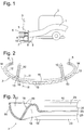
In Verlängerung der Längsträger
Ein unterer Stoßfängerquerträger
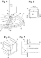
Wie insbesondere in der Draufsicht der
Die Öffnung
Das Ergebnis einer solchen Kollision ist in
Während an den Rippen
Die nach außen konvexe Krümmung des zentralen Abschnitts
Im hier betrachteten Fall, in dem der Dämpferkörper sechs Rippen
Natürlich könnten die Stirnflächen
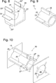
Das entfernte Stück hat zwar in der Darstellung der
An der Spitze
Ein Dämpferkörper
BezugszeichenlisteLIST OF REFERENCE NUMBERS
- 11
- Längsträgerlongitudinal beams
- 22
- Motorblockblock
- 33
- KühleraggregatA radiator unit
- 44
- Flanschflange
- 55
- Energieabsorberenergy absorber
- 66
- oberer StoßfängerquerträgerUpper bumper cross member
- 77
- unterer Stoßfängerquerträgerlower bumper crossmember
- 88th
- Befestigungsabschnittattachment section
- 99
- Vorsprunghead Start
- 1010
- Dämpferkörperdamper body
- 1111
- zentraler Abschnittcentral section
- 1212
- äußerer Abschnittouter section
- 1313
- BasisBase
- 1414
- Scheitelpunktvertex
- 1515
- Grundplattebaseplate
- 1616
- vordere Wandfront wall
- 1717
- Rinnegutter
- 1818
- Rinnegutter
- 1919
- Ripperib
- 2020
- Wandwall
- 2121
- Hauptabschnittmain section
- 2222
- Rinnegutter
- 2323
- Ripperib
- 2424
- Öffnungopening
- 2525
- Spitzetop
- 2626
- Grundplattebaseplate
- 2727
- Lückegap
- 2828
- Schlitzslot
- 2929
- Stirnflächeface
ZITATE ENTHALTEN IN DER BESCHREIBUNG QUOTES INCLUDE IN THE DESCRIPTION
Diese Liste der vom Anmelder aufgeführten Dokumente wurde automatisiert erzeugt und ist ausschließlich zur besseren Information des Lesers aufgenommen. Die Liste ist nicht Bestandteil der deutschen Patent- bzw. Gebrauchsmusteranmeldung. Das DPMA übernimmt keinerlei Haftung für etwaige Fehler oder Auslassungen.This list of the documents listed by the applicant has been generated automatically and is included solely for the better information of the reader. The list is not part of the German patent or utility model application. The DPMA assumes no liability for any errors or omissions.
Zitierte PatentliteraturCited patent literature
- AT 394004 B [0004] AT 394004 B [0004]
Claims (13)
Priority Applications (1)
| Application Number | Priority Date | Filing Date | Title |
|---|---|---|---|
| DE201210024979 DE102012024979A1 (en) | 2012-12-20 | 2012-12-20 | Crash energy absorber for motor car, has main portion arranged in front of aperture of base plate and provided with projecting ribs, which are outwardly projected on edge of aperture, where ribs are elongated in impact direction |
Applications Claiming Priority (1)
| Application Number | Priority Date | Filing Date | Title |
|---|---|---|---|
| DE201210024979 DE102012024979A1 (en) | 2012-12-20 | 2012-12-20 | Crash energy absorber for motor car, has main portion arranged in front of aperture of base plate and provided with projecting ribs, which are outwardly projected on edge of aperture, where ribs are elongated in impact direction |
Publications (1)
| Publication Number | Publication Date |
|---|---|
| DE102012024979A1 true DE102012024979A1 (en) | 2014-06-26 |
Family
ID=50878278
Family Applications (1)
| Application Number | Title | Priority Date | Filing Date |
|---|---|---|---|
| DE201210024979 Withdrawn DE102012024979A1 (en) | 2012-12-20 | 2012-12-20 | Crash energy absorber for motor car, has main portion arranged in front of aperture of base plate and provided with projecting ribs, which are outwardly projected on edge of aperture, where ribs are elongated in impact direction |
Country Status (1)
| Country | Link |
|---|---|
| DE (1) | DE102012024979A1 (en) |
Cited By (2)
| Publication number | Priority date | Publication date | Assignee | Title |
|---|---|---|---|---|
| GB2522740A (en) * | 2013-11-15 | 2015-08-05 | Gm Global Tech Operations Inc | Bumper support for a vehicle |
| DE102018109992A1 (en) * | 2018-04-25 | 2019-10-31 | Benteler Automobiltechnik Gmbh | Automotive bumper assembly and method of manufacture |
Citations (4)
| Publication number | Priority date | Publication date | Assignee | Title |
|---|---|---|---|---|
| US3779591A (en) * | 1971-08-23 | 1973-12-18 | W Rands | Energy absorbing device |
| AT394004B (en) | 1990-06-25 | 1992-01-27 | Austria Metall | SHOCK ABSORBERS, ESPECIALLY FOR MOTOR VEHICLES |
| DE10145446A1 (en) * | 2000-09-14 | 2002-03-28 | Reynolds Aluminium Bv | Structure to absorb energy at a vehicle, in the event of an impact collision, has a profiled body with external ribs and a limit stop, to take up forces in the mounting on towing the vehicle without durable distortion |
| US7484781B1 (en) * | 2007-11-28 | 2009-02-03 | Isaak Garber | Constant deceleration bumper |
-
2012
- 2012-12-20 DE DE201210024979 patent/DE102012024979A1/en not_active Withdrawn
Patent Citations (4)
| Publication number | Priority date | Publication date | Assignee | Title |
|---|---|---|---|---|
| US3779591A (en) * | 1971-08-23 | 1973-12-18 | W Rands | Energy absorbing device |
| AT394004B (en) | 1990-06-25 | 1992-01-27 | Austria Metall | SHOCK ABSORBERS, ESPECIALLY FOR MOTOR VEHICLES |
| DE10145446A1 (en) * | 2000-09-14 | 2002-03-28 | Reynolds Aluminium Bv | Structure to absorb energy at a vehicle, in the event of an impact collision, has a profiled body with external ribs and a limit stop, to take up forces in the mounting on towing the vehicle without durable distortion |
| US7484781B1 (en) * | 2007-11-28 | 2009-02-03 | Isaak Garber | Constant deceleration bumper |
Cited By (4)
| Publication number | Priority date | Publication date | Assignee | Title |
|---|---|---|---|---|
| GB2522740A (en) * | 2013-11-15 | 2015-08-05 | Gm Global Tech Operations Inc | Bumper support for a vehicle |
| US9290141B2 (en) | 2013-11-15 | 2016-03-22 | GM Global Technology Operations LLC | Bumper support for a vehicle |
| DE102018109992A1 (en) * | 2018-04-25 | 2019-10-31 | Benteler Automobiltechnik Gmbh | Automotive bumper assembly and method of manufacture |
| DE102018109992B4 (en) | 2018-04-25 | 2022-02-17 | Benteler Automobiltechnik Gmbh | Automobile bumper assembly and method of manufacture |
Similar Documents
| Publication | Publication Date | Title |
|---|---|---|
| DE60121110T2 (en) | Apparatus for absorbing impact energy and motor vehicle door with such a device | |
| DE112010006033T5 (en) | Vehicle bumper beam and method of making the same | |
| DE102014016044A1 (en) | Front end of a motor vehicle and bumper stiffening to | |
| DE102004008741A1 (en) | bumper system | |
| DE102011118327A1 (en) | Motor vehicle with crash box | |
| EP2676046B1 (en) | Bumper for vehicles with integrated pedestrian protection function | |
| DE10234928B4 (en) | Shock absorber for a two-wheeler | |
| DE102007012830A1 (en) | Pane cross beam structure for use on motor vehicle, has cross beam with carrier upper part that is formed with definable flexibility such that absorption of impact energy is permitted by plastic deformation of carrier upper part | |
| DE10143890A1 (en) | Front structure of a motor vehicle | |
| DE102016000599A1 (en) | crash box | |
| DE102011111237A1 (en) | Automotive body | |
| DE102015004416A1 (en) | Front end for a motor vehicle | |
| DE102009058288A1 (en) | Body for a motor vehicle | |
| DE102012011982B4 (en) | Airbag cover with an emblem and method of making the same | |
| DE102011120122A1 (en) | Automotive body | |
| DE102013019940B4 (en) | Airbag cover | |
| DE102012012157A1 (en) | Hood for a motor vehicle | |
| DE102011001690A1 (en) | Liner for use in inner-side of door of vehicle, has thinning part influencing deformation behavior of lining element such that region of lining element is movable laterally to effective direction of force during application of force | |
| EP1789272B1 (en) | Ventilation device and method for the production of a ventilation device | |
| DE102008004885A1 (en) | Motor vehicle foot rest, has bend shaped part made of flat material provided with U-shaped cross section and another set of retaining plates that are turned towards narrow side of flat materials in forward driving direction of motor vehicle | |
| DE602004011657T2 (en) | Lateral reinforcement for picking up bumping quantities for vehicle doors | |
| DE202011109253U1 (en) | Automotive body | |
| DE202009017786U1 (en) | Body for a motor vehicle | |
| DE102011119105A1 (en) | Motor car, has A-pillar for limiting windscreen aperture and windscreen, and edge area secured at A-pillar by intermediate piece, where intermediate piece is connected with A-pillar over set of corrodible weak points | |
| EP2335982B1 (en) | Absorber element for a motor vehicle |
Legal Events
| Date | Code | Title | Description |
|---|---|---|---|
| R079 | Amendment of ipc main class |
Free format text: PREVIOUS MAIN CLASS: B60R0019180000 Ipc: B60R0019340000 |
|
| R163 | Identified publications notified | ||
| R005 | Application deemed withdrawn due to failure to request examination |