DE102015225736A1 - Method and device for determining the injection rate of an injection valve - Google Patents
Method and device for determining the injection rate of an injection valve Download PDFInfo
- Publication number
- DE102015225736A1 DE102015225736A1 DE102015225736.3A DE102015225736A DE102015225736A1 DE 102015225736 A1 DE102015225736 A1 DE 102015225736A1 DE 102015225736 A DE102015225736 A DE 102015225736A DE 102015225736 A1 DE102015225736 A1 DE 102015225736A1
- Authority
- DE
- Germany
- Prior art keywords
- injection
- measuring chamber
- pressure
- injection rate
- piston
- Prior art date
- Legal status (The legal status is an assumption and is not a legal conclusion. Google has not performed a legal analysis and makes no representation as to the accuracy of the status listed.)
- Withdrawn
Links
- 238000002347 injection Methods 0.000 title claims abstract description 119
- 239000007924 injection Substances 0.000 title claims abstract description 119
- 238000000034 method Methods 0.000 title claims abstract description 23
- 238000012360 testing method Methods 0.000 claims abstract description 23
- 239000012530 fluid Substances 0.000 claims abstract description 21
- 238000013178 mathematical model Methods 0.000 claims abstract description 9
- 238000012937 correction Methods 0.000 claims abstract description 8
- 238000006073 displacement reaction Methods 0.000 claims description 5
- 239000006096 absorbing agent Substances 0.000 claims description 4
- 230000035939 shock Effects 0.000 claims description 4
- 230000033001 locomotion Effects 0.000 description 13
- 238000004364 calculation method Methods 0.000 description 11
- 238000005259 measurement Methods 0.000 description 7
- 238000013016 damping Methods 0.000 description 4
- 238000011161 development Methods 0.000 description 3
- 230000018109 developmental process Effects 0.000 description 3
- 230000010355 oscillation Effects 0.000 description 3
- 239000007921 spray Substances 0.000 description 3
- 238000002485 combustion reaction Methods 0.000 description 2
- 230000001934 delay Effects 0.000 description 2
- 238000001514 detection method Methods 0.000 description 2
- 238000010586 diagram Methods 0.000 description 2
- BUHVIAUBTBOHAG-FOYDDCNASA-N (2r,3r,4s,5r)-2-[6-[[2-(3,5-dimethoxyphenyl)-2-(2-methylphenyl)ethyl]amino]purin-9-yl]-5-(hydroxymethyl)oxolane-3,4-diol Chemical compound COC1=CC(OC)=CC(C(CNC=2C=3N=CN(C=3N=CN=2)[C@H]2[C@@H]([C@H](O)[C@@H](CO)O2)O)C=2C(=CC=CC=2)C)=C1 BUHVIAUBTBOHAG-FOYDDCNASA-N 0.000 description 1
- 238000013459 approach Methods 0.000 description 1
- 238000004590 computer program Methods 0.000 description 1
- 238000009795 derivation Methods 0.000 description 1
- 230000008030 elimination Effects 0.000 description 1
- 238000003379 elimination reaction Methods 0.000 description 1
- 230000005284 excitation Effects 0.000 description 1
- 239000000446 fuel Substances 0.000 description 1
- 238000005457 optimization Methods 0.000 description 1
- 230000003534 oscillatory effect Effects 0.000 description 1
- 239000000243 solution Substances 0.000 description 1
- 238000012731 temporal analysis Methods 0.000 description 1
Images

Classifications
-
- F—MECHANICAL ENGINEERING; LIGHTING; HEATING; WEAPONS; BLASTING
- F02—COMBUSTION ENGINES; HOT-GAS OR COMBUSTION-PRODUCT ENGINE PLANTS
- F02M—SUPPLYING COMBUSTION ENGINES IN GENERAL WITH COMBUSTIBLE MIXTURES OR CONSTITUENTS THEREOF
- F02M65/00—Testing fuel-injection apparatus, e.g. testing injection timing ; Cleaning of fuel-injection apparatus
- F02M65/001—Measuring fuel delivery of a fuel injector
-
- G—PHYSICS
- G01—MEASURING; TESTING
- G01F—MEASURING VOLUME, VOLUME FLOW, MASS FLOW OR LIQUID LEVEL; METERING BY VOLUME
- G01F3/00—Measuring the volume flow of fluids or fluent solid material wherein the fluid passes through the meter in successive and more or less isolated quantities, the meter being driven by the flow
- G01F3/02—Measuring the volume flow of fluids or fluent solid material wherein the fluid passes through the meter in successive and more or less isolated quantities, the meter being driven by the flow with measuring chambers which expand or contract during measurement
- G01F3/04—Measuring the volume flow of fluids or fluent solid material wherein the fluid passes through the meter in successive and more or less isolated quantities, the meter being driven by the flow with measuring chambers which expand or contract during measurement having rigid movable walls
- G01F3/14—Measuring the volume flow of fluids or fluent solid material wherein the fluid passes through the meter in successive and more or less isolated quantities, the meter being driven by the flow with measuring chambers which expand or contract during measurement having rigid movable walls comprising reciprocating pistons, e.g. reciprocating in a rotating body
- G01F3/16—Measuring the volume flow of fluids or fluent solid material wherein the fluid passes through the meter in successive and more or less isolated quantities, the meter being driven by the flow with measuring chambers which expand or contract during measurement having rigid movable walls comprising reciprocating pistons, e.g. reciprocating in a rotating body in stationary cylinders
-
- F—MECHANICAL ENGINEERING; LIGHTING; HEATING; WEAPONS; BLASTING
- F02—COMBUSTION ENGINES; HOT-GAS OR COMBUSTION-PRODUCT ENGINE PLANTS
- F02M—SUPPLYING COMBUSTION ENGINES IN GENERAL WITH COMBUSTIBLE MIXTURES OR CONSTITUENTS THEREOF
- F02M2200/00—Details of fuel-injection apparatus, not otherwise provided for
- F02M2200/30—Fuel-injection apparatus having mechanical parts, the movement of which is damped
- F02M2200/304—Fuel-injection apparatus having mechanical parts, the movement of which is damped using hydraulic means
Landscapes
- Engineering & Computer Science (AREA)
- Chemical & Material Sciences (AREA)
- Combustion & Propulsion (AREA)
- Mechanical Engineering (AREA)
- General Engineering & Computer Science (AREA)
- Physics & Mathematics (AREA)
- Fluid Mechanics (AREA)
- General Physics & Mathematics (AREA)
- Measuring Volume Flow (AREA)
- Testing Of Engines (AREA)
- Injection Moulding Of Plastics Or The Like (AREA)
Abstract
Die Erfindung betrifft ein Verfahren zur Bestimmung einer Einspritzrate eines Einspritzventils (1) mit Hilfe eines mathematischen Modells, dem Messwerte zugrunde gelegt werden, die den Hub (x) eines eine Messkammer (2) begrenzenden Kolbens (3) während der Einspritzung eines Prüffluids (4) in die Messkammer (2) umfassen, wobei eine Korrektur der Einspritzrate auf Basis eines weiteren Messwerts durchgeführt wird. Erfindungsgemäß wird der Druck (pa) in einem Adaptervolumen (5), über welches das Einspritzventil (1) mit der Messkammer (2) verbunden ist, als weiterer Messwert zur Korrektur der Einspritzrate verwendet. Ferner wird eine Vorrichtung zur Bestimmung einer Einspritzrate eines Einspritzventils angegeben.The invention relates to a method for determining an injection rate of an injection valve (1) with the aid of a mathematical model which is based on measured values which determine the stroke (x) of a piston (3) delimiting a measuring chamber (2) during the injection of a test fluid (4 ) into the measuring chamber (2), whereby a correction of the injection rate is carried out on the basis of a further measured value. According to the invention, the pressure (pa) in an adapter volume (5) via which the injection valve (1) is connected to the measuring chamber (2) is used as a further measured value for correcting the injection rate. Furthermore, a device for determining an injection rate of an injection valve is specified.
Description
Die Erfindung betrifft ein Verfahren zur Bestimmung der Einspritzrate eines Einspritzventils mit den Merkmalen des Oberbegriffs des Anspruchs 1. Ferner wird eine Vorrichtung zur Bestimmung der Einspritzrate angegeben, die zur Durchführung des erfindungsgemäßen Verfahrens geeignet ist.The invention relates to a method for determining the injection rate of an injection valve with the features of the preamble of claim 1. Furthermore, a device for determining the injection rate is specified, which is suitable for carrying out the method according to the invention.
Stand der TechnikState of the art
In der Entwicklung und Funktionsprüfung von Einspritzventilen, insbesondere von Einspritzventilen zum Einspritzen von Brennstoff in einen Brennraum einer Brennkraftmaschine, hat sich zur hochgenauen Messung der Einspritzmenge ein Verfahren bewährt, das beispielhaft in der Offenlegungsschrift
Die Einspritzmenge lässt sich dann auf der Grundlage der folgenden Gleichung berechnen:
Durch zeitliche Ableitung der Einspritzmenge lässt sich – im Prinzip – nach folgender Gleichung die Einspritzrate bestimmen:
Wegen der dynamischen Eigenschaften des die Messkammer begrenzenden Kolbens werden die während der Einspritzung erfassten Messsignale jedoch von störenden Schwingungen des Feder-Masse-Systems überlagert, so dass dieser Ansatz zur Bestimmung der Einspritzrate für eine zeitlich hoch aufgelöste Analyse des Einspritzverlaufs, die für die Optimierung des Einspritzventils erforderlich ist, nur begrenzt anwendbar ist.Because of the dynamic properties of the measuring chamber limiting piston, however, the measurement signals detected during the injection are superimposed by disturbing vibrations of the spring-mass system, so that this approach for determining the injection rate for a high-temporal analysis of the injection curve, which for the optimization of Injector is required, is limited.
In der Offenlegungsschrift
Da bei der Entwicklung und Funktionsprüfung von Einspritzventilen immer mehr Merkmale anhand des Einspritzratenverlaufs bestimmt werden, beispielsweise der Einspritzbeginn, das Einspritzratenmaximum und/oder das Einspritzende, bedarf es genauer Messwerte, um zu verlässlichen Ergebnissen zu kommen.Since the development and functional testing of injection valves more and more features are determined based on the injection rate curve, for example, the start of injection, the injection rate maximum and / or the end of injection, it requires accurate readings to get reliable results.
Ausgehend von dem vorstehend genannten Stand der Technik liegt der vorliegenden Erfindung daher die Aufgabe zugrunde, ein Verfahren und eine Vorrichtung anzugeben, welche eine möglichst präzise Bestimmung der Einspritzrate eines Einspritzventils ermöglichen.Based on the above-mentioned prior art, the present invention therefore has the object of specifying a method and a device which allow the most accurate possible determination of the injection rate of an injection valve.
Zur Lösung der Aufgabe werden das Verfahren mit den Merkmalen des Anspruchs 1 und die Vorrichtung mit den Merkmalen des Anspruchs 5 angegeben. Vorteilhafte Weiterbildungen der Erfindung sind den jeweiligen Unteransprüchen zu entnehmen.To achieve the object, the method with the features of claim 1 and the device with the features of claim 5 are given. Advantageous developments of the invention can be found in the respective subclaims.
Offenbarung der ErfindungDisclosure of the invention
Bei dem vorgeschlagenen Verfahren wird die Einspritzrate eines Einspritzventils ebenfalls mit Hilfe eines mathematischen Modells bestimmt. Dem mathematischen Modell werden Messwerte zugrunde gelegt, die den Hub eines eine Messkammer begrenzenden Kolbens während der Einspritzung eines Prüffluids in die Messkammer umfassen. Ferner wird eine Korrektur der Einspritzrate auf Basis eines weiteren Messwerts durchgeführt. Erfindungsgemäß wird als weiterer Messwert der Druck in einem Adaptervolumen verwendet, über welches das Einspritzventil mit der Messkammer verbunden ist.In the proposed method, the injection rate of an injection valve is also determined by means of a mathematical model. The mathematical model is based on measured values which comprise the stroke of a piston bounding a measuring chamber during the injection of a test fluid into the measuring chamber. Furthermore, a correction of the injection rate is carried out on the basis of another measured value. According to the invention, the pressure in an adapter volume, via which the injection valve is connected to the measuring chamber, is used as a further measured value.
Die Einspritzung des Prüffluids in die Messkammer erfolgt demnach nicht unmittelbar, sonder mittelbar über ein Adaptervolumen, das in einem Adapter zur Aufnahme des Einspritzventils ausgebildet ist. Der Adapter erleichtert die Verbindung des Einspritzventils mit der Messeinrichtung, insbesondere kann das Einspritzventil über den Adapter fluiddicht mit der Messeinrichtung verbunden werden. Dies gilt insbesondere, wenn eine entsprechende Dichtung vorgesehen ist.The injection of the test fluid into the measuring chamber is therefore not directly, but indirectly via an adapter volume, which is formed in an adapter for receiving the injection valve is. The adapter facilitates the connection of the injection valve with the measuring device, in particular, the injection valve can be fluid-tightly connected to the measuring device via the adapter. This is especially true if a corresponding seal is provided.
Die Verwendung eines Adapters zur Aufnahme des Einspritzventils ist aus dem Stand der Technik grundsätzlich bekannt. Vernachlässigt wurde bislang jedoch, dass das Adaptervolumen zu einer zeitlichen Verzögerung und/oder Dämpfung der Einspritzung und somit zu einem zeitversetzten und/oder abgerundeten Einspritzratenverlauf führt, wenn lediglich der Kolbenhubverlauf bei der Berechnung berücksichtigt wird. Hinzu kommt, dass auch eine Adapterdichtung aufgrund ihres viskoelastischen Verhaltens zu einer Schwingung führen kann, die den Kolbenhub überlagert.The use of an adapter for receiving the injection valve is known in principle from the prior art. So far, however, it has been neglected that the adapter volume leads to a time delay and / or damping of the injection and thus to a time-offset and / or rounded injection rate profile, if only the piston stroke profile is taken into account in the calculation. In addition, an adapter seal, due to its viscoelastic behavior, can lead to vibration superimposed on the piston stroke.
Wird jedoch entsprechend dem erfindungsgemäßen Verfahren zusätzlich der Druck im Adaptervolumen erfasst und bei der Einspritzratenberechnung berücksichtigt, können sowohl schwingungsbedingte Störgrößen, als auch Zeitverzögerungen bzw. Verrundungen des Einspritzratenverlaufs beseitigt werden.However, according to the method according to the invention, if the pressure in the adapter volume is additionally recorded and taken into account in the injection rate calculation, it is possible to eliminate both disturbance variables due to oscillation and time delays or rounding off of the injection rate profile.
Die Einspritzrate kann dann wie folgt berechnet werden: ![]()
![]()
Der Druckverlauf im Adaptervolumen stellt somit neben dem Kolbenhubverlauf sowie der Temperatur und dem Druck in der Messkammer eine weitere Messgröße dar, die der Berechnung der Einspritzrate nach dem erfindungsgemäßen Verfahren zugrunde gelegt wird. Das Adaptervolumen und die Querschnittsfläche des Kolbens stellen bekannte Größen dar. Die Berechnung erfolgt vorzugsweise in Echtzeit.The pressure profile in the adapter volume thus represents, in addition to the piston stroke profile as well as the temperature and the pressure in the measuring chamber, a further measured variable which is used to calculate the injection rate according to the method according to the invention. The adapter volume and the cross-sectional area of the piston represent known quantities. The calculation is preferably carried out in real time.
Der zusätzliche Geräteaufwand zur Durchführung des erfindungsgemäßen Verfahrens ist gering. Es bedarf lediglich eines weiteren Drucksensors, der dem Adaptervolumen zugeordnet ist, um während der Einspritzung den Druck im Adaptervolumen zu erfassen. Das heißt, dass bereits vorhandene Messeinrichtungen verwendet werden können, sofern sie um einen entsprechenden Drucksensor erweitert werden.The additional equipment costs for carrying out the method according to the invention is low. It only requires a further pressure sensor, which is assigned to the adapter volume to detect the pressure in the adapter volume during the injection. This means that already existing measuring devices can be used, provided that they are extended by a corresponding pressure sensor.
Die Temperatur und der Druck in der Messkammer werden vorzugsweise mittels eines Temperatursensors und eines Drucksensors erfasst, die jeweils der Messkammer zugeordnet sind. Die Erfassung der Temperatur und des Drucks in der Messkammer ist zur Bestimmung der Rohdichte des Prüffluids erforderlich.The temperature and the pressure in the measuring chamber are preferably detected by means of a temperature sensor and a pressure sensor, which are respectively associated with the measuring chamber. The detection of the temperature and pressure in the measuring chamber is required to determine the bulk density of the test fluid.
Weiterhin bevorzugt werden die während der Einspritzung erfassten Messwerte als Messsignale an eine Steuereinheit weitergeleitet. Um auf der Basis der Messsignale die Einspritzrate zu berechnen, ist vorzugsweise in der Steuereinheit das mathematische Modell zur Berechnung der Einspritzrate hinterlegt.Further preferably, the measured values acquired during the injection are forwarded as measuring signals to a control unit. In order to calculate the injection rate on the basis of the measurement signals, the mathematical model for calculating the injection rate is preferably stored in the control unit.
Die ferner zur Lösung der eingangs genannten Aufgabe vorgeschlagene Vorrichtung zur Bestimmung der Einspritzrate eines Einspritzventils umfasst eine von einem Kolben begrenzte Messkammer, die über ein Adaptervolumen, das in einem Adapter zur Aufnahme des Einspritzventils ausgebildet ist, mit dem Einspritzventil verbindbar ist, so dass mittels des Einspritzventils ein Prüffluid in die Messkammer einspritzbar ist. Ferner umfasst die Vorrichtung eine Wegmesseinrichtung zur Erfassung des Kolbenhubs während einer Einspritzung. Erfindungsgemäß ist dem Adaptervolumen ein Drucksensor zugeordnet, mittels dessen der Druck im Adaptervolumen während einer Einspritzung erfassbar ist.The device further proposed for the solution of the above-mentioned object for determining the injection rate of an injection valve comprises a limited by a piston measuring chamber, which is connected via an adapter volume, which is formed in an adapter for receiving the injector with the injection valve, so that by means of Injector, a test fluid is injected into the measuring chamber. Furthermore, the device comprises a displacement measuring device for detecting the piston stroke during an injection. According to the invention, the adapter volume is assigned a pressure sensor, by means of which the pressure in the adapter volume can be detected during an injection.
Durch den Drucksensor, der dem Adaptervolumen zugeordnet ist, ist die vorgeschlagene Vorrichtung zur Durchführung des zuvor beschriebenen erfindungsgemäßen Verfahrens geeignet. Denn neben dem Kolbenhubverlauf ist auch der Druckverlauf im Adaptervolumen erfassbar, anhand dessen eine Korrektur des Einspritzratenverlaufs vorgenommen wird. Durch Schwingungen bedingte Störgrößen sowie Zeitverzögerungen bzw. Dämpfungen des Einspritzratenverlaufs aufgrund des zwischengeschalteten Adaptervolumens können auf diese Weise beseitigt werden.By the pressure sensor, which is assigned to the adapter volume, the proposed device for carrying out the method according to the invention described above is suitable. Because in addition to the Kolbenhubverlauf and the pressure profile in the adapter volume can be detected, based on which a correction of the injection rate profile is made. Due to vibrations disturbances and time delays or attenuations of the injection rate due to the intermediate adapter volume can be eliminated in this way.
Bevorzugt ist zwischen dem Adaptervolumen und der Messkammer ein Spritzdämpfer angeordnet. Der Spritzdämpfer verhindert, dass die Einspritzstrahlen des über das Adaptervolumen in die Messkammer eingespritzten Prüffluids direkt auf die Oberseite des Kolbens auftreffen und diesen zum Schwingen bringen.Preferably, a spray damper is arranged between the adapter volume and the measuring chamber. The spray damper prevents the injection jets of the test fluid injected into the measuring chamber via the adapter volume from striking the top of the piston and causing it to vibrate.
Der Spritzdämpfer führt zu einem Staudruck im Adaptervolumen und damit zu einer weiteren Verzögerung bzw. Dämpfung der Einspritzung. Mittels des erfindungsgemäßen Verfahrens bzw. der erfindungsgemäßen Vorrichtung wird jedoch auch der Staudruck im Adaptervolumen während einer Einspritzung erfasst, so dass der Staudruckverlauf durch den Spritzdämpfer bei der Berechnung der Einspritzrate berücksichtigt wird. Die Berechnung kommt somit zu sehr genauen Ergebnissen.The spray damper leads to a back pressure in the adapter volume and thus to a further delay or damping of the injection. By means of the method according to the invention or the device according to the invention, however, the dynamic pressure in the adapter volume during an injection is also detected, so that the back pressure curve through the dashpot in the calculation of the Injection rate is taken into account. The calculation thus comes to very accurate results.
Ferner wird vorgeschlagen, dass der Messkammer ein Temperatursensor und ein Drucksensor zugeordnet sind. Mittels dieser Sensoren sind die Temperatur und der It is also proposed that the measuring chamber is associated with a temperature sensor and a pressure sensor. By means of these sensors are the temperature and the
Druck in der Messkammer während einer Einspritzung erfassbar. Diese Messwerte ermöglichen eine genaue Bestimmung der Rohdichte des Prüffluids.Pressure in the measuring chamber during an injection detectable. These measurements allow accurate determination of the bulk density of the test fluid.
Vorteilhafterweise umfasst die Vorrichtung zur Bestimmung der Einspritzrate eines Einspritzventils eine Steuereinheit. Die Steuereinheit ermöglicht eine genaue Berechnung der Einspritzrate anhand der ihr zur Verfügung gestellten Messwerte. Um die Messwerte an die Steuereinheit weiterzuleiten, ist diese bevorzugt über Steuerleitungen mit der Wegmesseinrichtung, dem Druck- und Temperatursensor in der Messkammer und dem Drucksensor in dem Adaptervolumen verbunden. Die Messwerte werden demnach als Messsignale von der jeweiligen Messeinrichtung an die Steuereinheit geschickt. Da die Berechnung der Einspritzrate mit Hilfe des mathematischen Modells erfolgt, ist dieses weiterhin vorzugsweise als Computerprogramm in der Steuereinheit hinterlegt.Advantageously, the device for determining the injection rate of an injection valve comprises a control unit. The control unit enables an accurate calculation of the injection rate based on the measured values provided to it. In order to forward the measured values to the control unit, it is preferably connected via control lines to the displacement measuring device, to the pressure and temperature sensor in the measuring chamber and to the pressure sensor in the adapter volume. The measured values are therefore sent as measurement signals from the respective measuring device to the control unit. Since the calculation of the injection rate takes place with the aid of the mathematical model, this is furthermore preferably stored as a computer program in the control unit.
Bevorzugt ist die Messkammer der erfindungsgemäßen Vorrichtung mit einem Entleerventil verbunden. Der Druck in der Messkammer ist durch eine Gegendruckkraft steuerbar. Da der in der Messkammer vorhandene Druck eine Druckkraft auf den die Messkammer begrenzenden Kolben bewirkt, ist dieser ferner bevorzugt auf seiner der Messkammer abgewandten Seite von einer Gegendruckkraft beaufschlagt, die durch ein weiteres druckbeaufschlagtes Volumen, insbesondere ein Gasvolumen, und/oder durch eine Feder erzeugt wird.Preferably, the measuring chamber of the device according to the invention is connected to an emptying valve. The pressure in the measuring chamber can be controlled by a counterpressure force. Since the pressure present in the measuring chamber causes a compressive force on the piston bounding the measuring chamber, it is also preferably acted upon on its side facing away from the measuring chamber by a counterpressure force which is generated by a further pressurized volume, in particular a gas volume, and / or by a spring becomes.
Darüber hinaus bevorzugt ist die erfindungsgemäße Vorrichtung zur Durchführung des erfindungsgemäßen Verfahrens geeignet.In addition, the device according to the invention is preferably suitable for carrying out the method according to the invention.
Das erfindungsgemäße Verfahren und die erfindungsgemäße Vorrichtung werden nachfolgend anhand der beigefügten Zeichnungen näher erläutert. Diese zeigen:The method according to the invention and the device according to the invention are explained in more detail below with reference to the attached drawings. These show:
Ausführliche Beschreibung der ZeichnungenDetailed description of the drawings
Die in der
Zur Bestimmung der Einspritzrate eines Einspritzventils
Die Einspritzung des Prüffluids
Die lediglich mittelbar über das Adaptervolumen
Die in der ![]()
![]()
Die Dichteänderungen in Abhängigkeit von der vorliegenden Temperatur ![]()
![]()
Der mittels des weiteren Drucksensors
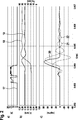
Die im oberen Bildteil a) dargestellte Kurve zeigt die Dauer der Bestromung eines Aktuators (nicht dargestellt) eines Einspritzventils
Im unteren Bildteil c) ist der Einspritzratenverlauf dargestellt, wobei die Kurve
ZITATE ENTHALTEN IN DER BESCHREIBUNG QUOTES INCLUDE IN THE DESCRIPTION
Diese Liste der vom Anmelder aufgeführten Dokumente wurde automatisiert erzeugt und ist ausschließlich zur besseren Information des Lesers aufgenommen. Die Liste ist nicht Bestandteil der deutschen Patent- bzw. Gebrauchsmusteranmeldung. Das DPMA übernimmt keinerlei Haftung für etwaige Fehler oder Auslassungen.This list of the documents listed by the applicant has been generated automatically and is included solely for the better information of the reader. The list is not part of the German patent or utility model application. The DPMA assumes no liability for any errors or omissions.
Zitierte PatentliteraturCited patent literature
- DE 10107032 A1 [0002] DE 10107032 A1 [0002]
- DE 102013212419 A1 [0006] DE 102013212419 A1 [0006]
Claims (12)
Priority Applications (7)
| Application Number | Priority Date | Filing Date | Title |
|---|---|---|---|
| DE102015225736.3A DE102015225736A1 (en) | 2015-12-17 | 2015-12-17 | Method and device for determining the injection rate of an injection valve |
| PCT/EP2016/078959 WO2017102292A1 (en) | 2015-12-17 | 2016-11-28 | Method and device for determining the injection rate of an injection valve |
| EP16801516.2A EP3390808B1 (en) | 2015-12-17 | 2016-11-28 | Method and device for determining the injection rate of an injection valve |
| KR1020187019909A KR20180095581A (en) | 2015-12-17 | 2016-11-28 | Method and apparatus for determining the injection rate of an injection valve |
| BR112018011880A BR112018011880A2 (en) | 2015-12-17 | 2016-11-28 | process and device for determining the injection rate of an injector valve |
| US16/063,493 US10947944B2 (en) | 2015-12-17 | 2016-11-28 | Method and device for determining the injection rate of an injection valve |
| CN201680073922.2A CN108368815B (en) | 2015-12-17 | 2016-11-28 | Method and device for determining the injection rate of an injection valve |
Applications Claiming Priority (1)
| Application Number | Priority Date | Filing Date | Title |
|---|---|---|---|
| DE102015225736.3A DE102015225736A1 (en) | 2015-12-17 | 2015-12-17 | Method and device for determining the injection rate of an injection valve |
Publications (1)
| Publication Number | Publication Date |
|---|---|
| DE102015225736A1 true DE102015225736A1 (en) | 2017-06-22 |
Family
ID=57396469
Family Applications (1)
| Application Number | Title | Priority Date | Filing Date |
|---|---|---|---|
| DE102015225736.3A Withdrawn DE102015225736A1 (en) | 2015-12-17 | 2015-12-17 | Method and device for determining the injection rate of an injection valve |
Country Status (7)
| Country | Link |
|---|---|
| US (1) | US10947944B2 (en) |
| EP (1) | EP3390808B1 (en) |
| KR (1) | KR20180095581A (en) |
| CN (1) | CN108368815B (en) |
| BR (1) | BR112018011880A2 (en) |
| DE (1) | DE102015225736A1 (en) |
| WO (1) | WO2017102292A1 (en) |
Cited By (2)
| Publication number | Priority date | Publication date | Assignee | Title |
|---|---|---|---|---|
| CN112943500A (en) * | 2021-03-11 | 2021-06-11 | 西华大学 | Device and method for simulating influence of plateau environment on spraying characteristic of aviation piston engine |
| WO2022199923A1 (en) * | 2021-03-23 | 2022-09-29 | Robert Bosch Gmbh | Device for measuring the injection amount of injection systems |
Families Citing this family (3)
| Publication number | Priority date | Publication date | Assignee | Title |
|---|---|---|---|---|
| CN109268186A (en) * | 2018-11-26 | 2019-01-25 | 北京理工大学 | Injector testing device and testing method |
| KR102754685B1 (en) * | 2021-12-13 | 2025-01-21 | 엘아이지넥스원 주식회사 | Apparatus for testing drainage and testing drainage system using the same |
| KR102831321B1 (en) | 2023-06-13 | 2025-07-08 | 인하대학교 산학협력단 | Fuel metering system and control method |
Citations (2)
| Publication number | Priority date | Publication date | Assignee | Title |
|---|---|---|---|---|
| DE10107032A1 (en) | 2001-02-15 | 2002-08-29 | Bosch Gmbh Robert | Method, computer program and device for measuring the injection quantity of injection nozzles, in particular for motor vehicles |
| DE102013212419A1 (en) | 2013-06-27 | 2014-12-31 | Robert Bosch Gmbh | Method for determining the injection rate |
Family Cites Families (10)
| Publication number | Priority date | Publication date | Assignee | Title |
|---|---|---|---|---|
| DE3806129A1 (en) * | 1987-03-12 | 1988-09-22 | Daimler Benz Ag | Device for determining the rate of injection in an internal combustion engine or the like |
| DE3916419C2 (en) | 1989-05-19 | 1994-05-11 | Daimler Benz Ag | Electromagnetically controlled measuring device for volumetric measurement of injection quantities of a diesel injection pump |
| DE4321709A1 (en) | 1992-07-11 | 1994-01-13 | Volkswagen Ag | Fluid quantity test system for IC engine fuel injection valve - has piston which reciprocates in and out of measurement chamber according to pressure, and optical triangulation system which detects light reflected by piston end |
| FR2795139B1 (en) | 1999-06-18 | 2001-07-20 | Efs Sa | DEVICE FOR INSTANTLY ANALYZING THE CUT-BY-CUT INJECTION FLOW PROVIDED BY AN INJECTION SYSTEM USED IN A HEAT ENGINE |
| DE10100459A1 (en) * | 2001-01-08 | 2002-08-01 | Bosch Gmbh Robert | Device and method for measuring the injection quantity of injection systems, in particular for internal combustion engines of motor vehicles |
| KR100425035B1 (en) * | 2001-08-14 | 2004-03-30 | 학교법인 한양학원 | Method for measuring fuel injection rate of injection nozzle for diesel engine |
| FR2935757B1 (en) * | 2008-09-05 | 2010-09-24 | Efs Sa | METHOD FOR ANALYZING THE CUT-INJECTION FLOW RATE PROVIDED BY A FUEL INJECTION SYSTEM USED IN A HEAVY-DUTY THERMAL ENGINE |
| JP4835716B2 (en) * | 2009-03-25 | 2011-12-14 | 株式会社デンソー | Fuel injection state detection device |
| JP2013007341A (en) * | 2011-06-24 | 2013-01-10 | Denso Corp | Fuel-injection-condition estimating apparatus |
| FR2999647B1 (en) * | 2012-12-18 | 2017-10-27 | Continental Automotive France | METHOD FOR DETERMINING THE QUANTITY OF FUEL INJECTED IN AN ENGINE, IN PARTICULAR A DIESEL TYPE ENGINE |
-
2015
- 2015-12-17 DE DE102015225736.3A patent/DE102015225736A1/en not_active Withdrawn
-
2016
- 2016-11-28 KR KR1020187019909A patent/KR20180095581A/en not_active Withdrawn
- 2016-11-28 US US16/063,493 patent/US10947944B2/en active Active
- 2016-11-28 BR BR112018011880A patent/BR112018011880A2/en not_active Application Discontinuation
- 2016-11-28 EP EP16801516.2A patent/EP3390808B1/en active Active
- 2016-11-28 CN CN201680073922.2A patent/CN108368815B/en active Active
- 2016-11-28 WO PCT/EP2016/078959 patent/WO2017102292A1/en not_active Ceased
Patent Citations (2)
| Publication number | Priority date | Publication date | Assignee | Title |
|---|---|---|---|---|
| DE10107032A1 (en) | 2001-02-15 | 2002-08-29 | Bosch Gmbh Robert | Method, computer program and device for measuring the injection quantity of injection nozzles, in particular for motor vehicles |
| DE102013212419A1 (en) | 2013-06-27 | 2014-12-31 | Robert Bosch Gmbh | Method for determining the injection rate |
Cited By (2)
| Publication number | Priority date | Publication date | Assignee | Title |
|---|---|---|---|---|
| CN112943500A (en) * | 2021-03-11 | 2021-06-11 | 西华大学 | Device and method for simulating influence of plateau environment on spraying characteristic of aviation piston engine |
| WO2022199923A1 (en) * | 2021-03-23 | 2022-09-29 | Robert Bosch Gmbh | Device for measuring the injection amount of injection systems |
Also Published As
| Publication number | Publication date |
|---|---|
| BR112018011880A2 (en) | 2018-11-27 |
| EP3390808A1 (en) | 2018-10-24 |
| WO2017102292A1 (en) | 2017-06-22 |
| EP3390808B1 (en) | 2020-09-23 |
| CN108368815A (en) | 2018-08-03 |
| KR20180095581A (en) | 2018-08-27 |
| CN108368815B (en) | 2020-10-16 |
| US10947944B2 (en) | 2021-03-16 |
| US20180372049A1 (en) | 2018-12-27 |
Similar Documents
| Publication | Publication Date | Title |
|---|---|---|
| EP3390808B1 (en) | Method and device for determining the injection rate of an injection valve | |
| EP3298266B1 (en) | Device for measuring the injection rate and measuring method | |
| WO2018054540A1 (en) | Device and method for dynamically calibrating pressure sensors | |
| DE10215865A1 (en) | Method for detecting a likely motor vehicle component failure, captures data in the form of parameters for the effects of related damage during the operation of a component | |
| WO2015155290A1 (en) | Method for determining the position and/or movement of a piston in a cylinder, and cylinder arrangement | |
| DE102020103403A1 (en) | IMPACT DETECTION SYSTEM FOR A VEHICLE AND IMPACT DETECTION METHOD FOR IT | |
| DE102013224706A1 (en) | Method for calculating the injection rate profile | |
| DE102019118904A1 (en) | Damping device of a vehicle and associated method | |
| DE102015208416B3 (en) | Determination method for determining an absolute value of an injected fuel mass | |
| WO2004079321A1 (en) | Method, device, and computer program for measuring the leakage of injection systems, especially for internal combustion engines of motor vehicles | |
| EP2821759B1 (en) | Method for determining the injection rate | |
| WO2011113659A1 (en) | Method and device for evaluating an injection member | |
| DE2012117A1 (en) | Device for sensing pressure changes or pressure values | |
| DE102017201877A1 (en) | Measuring arrangement and method for determining the time-related mass flow profile during an injection carried out by a fuel injector into a measuring space | |
| DE102015211178A1 (en) | Method for detecting misfiring of an internal combustion engine | |
| DE102006021937A1 (en) | Vibration damper`s wear condition testing method for use in motor vehicle, involves using operating temperature of vibration damper as parameter for wear condition based on excitation of damper | |
| DE10103974B4 (en) | Device for testing the filling pressure of an airbag gas storage | |
| DE102008007712A1 (en) | Active vibration isolation system | |
| DE3806129A1 (en) | Device for determining the rate of injection in an internal combustion engine or the like | |
| DE102015201817A1 (en) | Mass flow CNG valve | |
| DE102020111814A1 (en) | Procedure for leak testing a test body and test device as well as high-voltage storage | |
| DE102007001674A1 (en) | Method for determining drive torque of motor vehicle, involves determining drive torque from determined longitudinal acceleration of motor vehicle and determined change of height level at axle of motor vehicle | |
| EP1944502A1 (en) | Measuring device and measuring method for an injector | |
| DE102007008505A1 (en) | Method of operating a piezoelectric transducer and transducer device | |
| DE102019200205B4 (en) | Vibration damper with a sensor device |
Legal Events
| Date | Code | Title | Description |
|---|---|---|---|
| R005 | Application deemed withdrawn due to failure to request examination |