DE102015225745B4 - Electrostatic soot sensor - Google Patents
Electrostatic soot sensor Download PDFInfo
- Publication number
- DE102015225745B4 DE102015225745B4 DE102015225745.2A DE102015225745A DE102015225745B4 DE 102015225745 B4 DE102015225745 B4 DE 102015225745B4 DE 102015225745 A DE102015225745 A DE 102015225745A DE 102015225745 B4 DE102015225745 B4 DE 102015225745B4
- Authority
- DE
- Germany
- Prior art keywords
- electrode
- guard
- potential
- soot sensor
- soot
- Prior art date
- Legal status (The legal status is an assumption and is not a legal conclusion. Google has not performed a legal analysis and makes no representation as to the accuracy of the status listed.)
- Active
Links
- 239000004071 soot Substances 0.000 title claims abstract description 142
- 238000009413 insulation Methods 0.000 claims abstract description 26
- 238000005259 measurement Methods 0.000 claims description 34
- 238000000034 method Methods 0.000 claims description 7
- 239000007789 gas Substances 0.000 description 35
- 239000002245 particle Substances 0.000 description 23
- 238000002485 combustion reaction Methods 0.000 description 14
- XLYOFNOQVPJJNP-UHFFFAOYSA-N water Substances O XLYOFNOQVPJJNP-UHFFFAOYSA-N 0.000 description 10
- 230000005684 electric field Effects 0.000 description 8
- 238000011156 evaluation Methods 0.000 description 5
- 238000001035 drying Methods 0.000 description 4
- 238000011144 upstream manufacturing Methods 0.000 description 4
- 238000013459 approach Methods 0.000 description 3
- 238000001514 detection method Methods 0.000 description 3
- 238000004519 manufacturing process Methods 0.000 description 3
- CURLTUGMZLYLDI-UHFFFAOYSA-N Carbon dioxide Chemical compound O=C=O CURLTUGMZLYLDI-UHFFFAOYSA-N 0.000 description 2
- 239000000919 ceramic Substances 0.000 description 2
- 239000002800 charge carrier Substances 0.000 description 2
- 239000012141 concentrate Substances 0.000 description 2
- 230000002950 deficient Effects 0.000 description 2
- 238000003745 diagnosis Methods 0.000 description 2
- 238000010586 diagram Methods 0.000 description 2
- 238000005516 engineering process Methods 0.000 description 2
- 230000003287 optical effect Effects 0.000 description 2
- 230000035515 penetration Effects 0.000 description 2
- 230000001681 protective effect Effects 0.000 description 2
- OKTJSMMVPCPJKN-UHFFFAOYSA-N Carbon Chemical compound [C] OKTJSMMVPCPJKN-UHFFFAOYSA-N 0.000 description 1
- 238000000149 argon plasma sintering Methods 0.000 description 1
- 235000019568 aromas Nutrition 0.000 description 1
- 230000009286 beneficial effect Effects 0.000 description 1
- 230000015572 biosynthetic process Effects 0.000 description 1
- 238000009529 body temperature measurement Methods 0.000 description 1
- 230000000711 cancerogenic effect Effects 0.000 description 1
- 229910052799 carbon Inorganic materials 0.000 description 1
- 229910002092 carbon dioxide Inorganic materials 0.000 description 1
- 239000001569 carbon dioxide Substances 0.000 description 1
- 231100000315 carcinogenic Toxicity 0.000 description 1
- 230000015556 catabolic process Effects 0.000 description 1
- 229910010293 ceramic material Inorganic materials 0.000 description 1
- 239000013078 crystal Substances 0.000 description 1
- 238000013461 design Methods 0.000 description 1
- 238000011161 development Methods 0.000 description 1
- 230000018109 developmental process Effects 0.000 description 1
- 239000002283 diesel fuel Substances 0.000 description 1
- 238000001914 filtration Methods 0.000 description 1
- 229930195733 hydrocarbon Natural products 0.000 description 1
- 150000002430 hydrocarbons Chemical class 0.000 description 1
- 239000011810 insulating material Substances 0.000 description 1
- 239000007788 liquid Substances 0.000 description 1
- 239000000463 material Substances 0.000 description 1
- 125000003367 polycyclic group Chemical group 0.000 description 1
- 239000002244 precipitate Substances 0.000 description 1
- 238000000746 purification Methods 0.000 description 1
- 230000008929 regeneration Effects 0.000 description 1
- 238000011069 regeneration method Methods 0.000 description 1
Images

Classifications
-
- G—PHYSICS
- G01—MEASURING; TESTING
- G01N—INVESTIGATING OR ANALYSING MATERIALS BY DETERMINING THEIR CHEMICAL OR PHYSICAL PROPERTIES
- G01N15/00—Investigating characteristics of particles; Investigating permeability, pore-volume or surface-area of porous materials
- G01N15/06—Investigating concentration of particle suspensions
- G01N15/0656—Investigating concentration of particle suspensions using electric, e.g. electrostatic methods or magnetic methods
Landscapes
- Chemical & Material Sciences (AREA)
- Dispersion Chemistry (AREA)
- Physics & Mathematics (AREA)
- Health & Medical Sciences (AREA)
- Life Sciences & Earth Sciences (AREA)
- Analytical Chemistry (AREA)
- Biochemistry (AREA)
- General Health & Medical Sciences (AREA)
- General Physics & Mathematics (AREA)
- Immunology (AREA)
- Pathology (AREA)
- Investigating Or Analyzing Materials By The Use Of Electric Means (AREA)
Abstract
Elektrostatischer Rußsensor (1) mit einer Spannungsversorgung (6), wobei der elektrostatische Rußsensor (1) eine erste Elektrode (2), eine zweite Elektrode (3) und eine Guardelektrode (16)aufweist, wobei die erste Elektrode (2) und die zweite Elektrode (3) durch einen Isolationskörper (5) elektrisch voneinander isoliert sind und zwischen der ersten Elektrode (2) und der zweiten Elektrode (3) die Guardelektrode (16) angeordnet ist, wobei auch die Guardelektrode (16) durch den Isolationskörper (5) elektrisch von der ersten Elektrode (2) und der zweiten Elektrode (3) isoliert ist, wobei mit der Spannungsversorgung (6) ein erstes elektrisches Potential (14) an die erste Elektrode (2) angelegt ist und wobei mit der Spannungsversorgung (6) ein zweites elektrisches Potential (18) an die zweite Elektrode (2) angelegt ist, sodass eine elektrischen Spannung zwischen der ersten Elektrode (2) und der zweiten Elektrode (3) entsteht, dadurch gekennzeichnet, dass mit der Spannungsversorgung (6) an die Guardelektrode (16) ein Guardpotential angelegt ist, das in der Warmlaufphase des Rußsensors (1) einem ersten Guardpotential (19) entspricht und in der Messphase des Rußsensors (1) einem zweiten Guardpotential (20) entspricht, wobei die Spannungsversorgung (6) das an der Guardelektrode (16) anliegende Guardpotential mit dem Erreichen einer Taupunktfreigabe von dem ersten Guardpotential (19) auf das zweite Guardpotential (20) umschaltet.

Description
Die Erfindung betrifft einen elektrostatischen Rußsensor sowie ein Verfahren zum Betreiben eines elektrostatischen Rußsensors.The invention relates to an electrostatic soot sensor and a method for operating an electrostatic soot sensor.
Die Verringerung von Abgasemissionen bei Kraftfahrzeugen ist ein wichtiges Ziel bei der Entwicklung neuer Kraftfahrzeuge. Daher werden Verbrennungsprozesse in Brennkraftmaschinen thermodynamisch optimiert, so dass der Wirkungsgrad der Brennkraftmaschine deutlich verbessert wird. Im Kraftfahrzeugbereich werden zunehmend Dieselmotoren eingesetzt, die, bei moderner Bauart, einen sehr hohen Wirkungsgrad aufweisen. Der Nachteil dieser Verbrennungstechnik gegenüber optimierten Otto-Motoren ist jedoch ein deutlich erhöhter Ausstoß von Ruß. Der Ruß ist besonders durch die Anlagerung polyzyklischer Aromate stark krebserregend, worauf mit verschiedenen Vorschriften bereits reagiert wurde. So wurden beispielsweise Abgas-Emissionsnormen mit Höchstgrenzen für die Rußemission erlassen. Um die Abgas-Emissionsnormen flächendeckend für Kraftfahrzeuge mit Dieselmotoren erfüllen zu können, besteht die Notwendigkeit, preisgünstige Sensoren herzustellen, die den Rußgehalt im Abgasstrom des Kraftfahrzeuges zuverlässig messen.Reducing exhaust emissions from automobiles is an important goal in the development of new automobiles. Therefore, combustion processes in internal combustion engines are thermodynamically optimized so that the efficiency of the internal combustion engine is significantly improved. In the automotive sector, diesel engines are increasingly being used which, with a modern design, have a very high efficiency. The disadvantage of this combustion technology compared to optimized gasoline engines, however, is a significantly increased emission of soot. The soot is particularly carcinogenic due to the addition of polycyclic aromas, which has already been reacted to with various regulations. For example, exhaust emission standards with maximum limits for soot emissions have been issued. In order to be able to meet the exhaust gas emission standards nationwide for motor vehicles with diesel engines, there is a need to produce inexpensive sensors which reliably measure the soot content in the exhaust gas flow of the motor vehicle.
Der Einsatz derartiger Rußsensoren dient der Messung des aktuell ausgestoßenen Rußes, damit dem Motormanagement in einem Kraftfahrzeug in einer aktuellen Fahrsituation Informationen zukommen, um mit regelungstechnischen Anpassungen die Emissionswerte zu reduzieren. Darüber hinaus kann mit Hilfe der Rußsensoren eine aktive Abgasreinigung durch Abgas-Rußfilter eingeleitet werden oder eine Abgasrückführung zur Brennkraftmaschine erfolgen. Im Falle der Rußfilterung werden regenerierbare Filter verwendet, die einen wesentlichen Teil des Rußgehaltes aus dem Abgas herausfiltern. Benötigt werden Rußsensoren für die Detektion von Ruß, um die Funktion der Rußfilter zu überwachen bzw. um deren Regenerationszyklen zu steuern. The use of soot sensors of this type is used to measure the soot currently emitted, so that engine management in a motor vehicle receives information in a current driving situation in order to reduce the emission values by adapting the control technology. In addition, the soot sensors can be used to initiate active exhaust gas purification through exhaust soot filters or exhaust gas recirculation to the internal combustion engine. In the case of soot filtering, regenerable filters are used which filter out a substantial part of the soot content from the exhaust gas. Soot sensors are required for the detection of soot, to monitor the function of the soot filter or to control their regeneration cycles.
Dazu kann dem Rußfilter, der auch als Dieselpartikelfilter bezeichnet wird, ein Rußsensor vorgeschaltet sein und/oder ein Rußsensor nachgeschaltet sein.For this purpose, a soot sensor can be connected upstream of the soot filter, which is also referred to as a diesel particle filter, and / or a soot sensor can be connected downstream.
Der dem Dieselpartikelfilter vorgeschaltete Sensor dient zur Erhöhung der Systemsicherheit und zur Sicherstellung eines Betriebes des Dieselpartikelfilters unter optimalen Bedingungen. Da dies in hohem Maße von der im Dieselpartikelfilter eingelagerten Rußmenge abhängt, ist eine genaue Messung der Partikelkonzentration vor dem Dieselpartikelfiltersystem, insbesondere die Ermittlung einer hohen Partikelkonzentration vor dem Dieselpartikelfilter, von hoher Bedeutung.The sensor upstream of the diesel particle filter serves to increase system security and to ensure operation of the diesel particle filter under optimal conditions. Since this depends to a large extent on the amount of soot stored in the diesel particle filter, an exact measurement of the particle concentration upstream of the diesel particle filter system, in particular the determination of a high particle concentration upstream of the diesel particle filter, is of great importance.
Ein dem Dieselpartikelfilter nachgeschalteter Rußsensor bietet die Möglichkeit, eine fahrzeugeigene Diagnose vorzunehmen und dient ferner der Sicherstellung des korrekten Betriebes der Abgasnachbehandlungsanlage.A soot sensor downstream of the diesel particle filter offers the possibility of carrying out a vehicle-specific diagnosis and also serves to ensure the correct operation of the exhaust gas aftertreatment system.
Der Stand der Technik zeigt verschiedene Ansätze zur Detektion von Ruß. Ein in Laboratorien weithin verfolgter Ansatz besteht in der Verwendung der Lichtstreuung durch die Rußpartikel. Diese Vorgehensweise eignet sich für aufwändige Messgeräte. Wenn versucht wird, dies auch als mobiles Sensorsystem im Abgasstrang einzusetzen, muss festgestellt werden, dass Ansätze zur Realisierung eines optischen Sensors in einem Kraftfahrzeug mit sehr hohen Kosten verbunden sind. Weiterhin bestehen ungelöste Probleme bezüglich der Verschmutzung der benötigten optischen Fenster durch Verbrennungsabgase.The prior art shows different approaches for the detection of soot. One approach that has been widely followed in laboratories is to use light scattering from the soot particles. This procedure is suitable for complex measuring devices. If an attempt is also made to use this as a mobile sensor system in the exhaust system, it must be ascertained that approaches to realizing an optical sensor in a motor vehicle are associated with very high costs. Furthermore, there are unsolved problems regarding the pollution of the required optical windows by combustion exhaust gases.
Aus der
Weitere Verfahren und Vorrichtungen zum Betreiben von Ruß- bzw. Partikelsensoren sind aus der
Die
Bei diesen elektrostatischen Rußsensoren ändert sich der Strom zwischen den beiden Elektroden in Abhängigkeit von der Rußkonzentration im Abgasstrom. Die hier auftretenden Ströme sind jedoch relativ klein und deren Stromstärke liegt in der Größenordnung von nA. Daher muss die gesamte Messanordnung für diese elektrostatischen Rußsensoren sehr hochohmig ausgeführt sein.In these electrostatic soot sensors, the current between the two electrodes changes depending on the soot concentration in the exhaust gas flow. However, the currents occurring here are relatively small and their current strength is of the order of magnitude of nA. Therefore, the entire Measuring arrangement for these electrostatic soot sensors can be very high-resistance.
Ein Problem, das bei der Messung von Rußpartikeln mit Hilfe von elektrostatischen Rußsensoren im Abgasstrang eines Kraftfahrzeuges besteht, ist, dass ein kalter Rußsensor, zum Beispiel nach dem Start eines erkalteten Verbrennungsmotors, nicht zur Rußmessung verwendet werden kann, da sich Kondenswasser aus dem Abgasstrom auf und in dem Rußsensor ablagert und diesen zunächst unstabil für einen Hochspannungsbetrieb macht, was eine zuverlässige Rußmessung ausschließt. Im Abgas eines Verbrennungsmotors ist immer ein hoher Anteil von Wasser in der Gasphase vorhanden, da die Kohlenwasserstoffe zum Beispiel aus dem Dieselkraftstoff vorwiegend zu Wasser und Kohlendioxyd verbrennen. Solange der Rußsensor kalt ist, kondensiert das Wasser aus dem Abgas zu flüssigen Wasser auf den Elektroden und dem Isolationskörper und stört damit die Rußmessung nachhaltig. Daher muss mit dem Beginn der Rußmessung so lange gewartet werden, bis der Rußsensor derart warm geworden ist, dass kein Wasser aus dem Abgasstrom mehr auskondensieren kann und das schon auskondensierte Wasser aus dem Rußsensor abgetrocknet ist. Zu diesem Zeitpunkt erfolgt die sogenannte Taupunktfreigabe für den Rußsensor. Ausschließlich anhand von Motormodellen in Verbindung mit einer Temperaturmessung im Abgasstrom kann nur eine sehr ungenaue Taupunktfreigabe erfolgen, da die vollständige Trocknung des Rußsensors von sehr vielen Faktoren (zum Beispiel Umgebungstemperatur des Fahrzeuges, Luftfeuchtigkeit der Ansaugluft, Gasmassenstrom im Abgasstrang) abhängt.A problem that arises when measuring soot particles with the aid of electrostatic soot sensors in the exhaust line of a motor vehicle is that a cold soot sensor, for example after the start of a cooled internal combustion engine, cannot be used for soot measurement, since condensed water is present in the exhaust gas stream and deposits in the soot sensor and initially makes it unstable for high-voltage operation, which precludes reliable soot measurement. A high proportion of water is always present in the gas phase in the exhaust gas of an internal combustion engine, since the hydrocarbons, for example from diesel fuel, burn primarily to form water and carbon dioxide. As long as the soot sensor is cold, the water from the exhaust gas condenses into liquid water on the electrodes and the insulation body and thus permanently interferes with the soot measurement. Therefore, at the start of the soot measurement, you have to wait until the soot sensor has become so warm that water from the exhaust gas stream can no longer condense and the water that has already condensed out has dried out of the soot sensor. At this point the so-called dew point release for the soot sensor takes place. Only with the help of engine models in connection with a temperature measurement in the exhaust gas flow can only an inaccurate dew point release be made, since the complete drying of the soot sensor depends on many factors (e.g. ambient temperature of the vehicle, air humidity of the intake air, gas mass flow in the exhaust gas line).
Es ist eine Aufgabe der vorliegenden Erfindung, einen elektrostatischer Rußsensor mit einer Spannungsversorgung und ein Verfahren zum Betreiben eines elektrostatischen Rußsensors mit einer Spannungsversorgung anzugeben, mit dem zuverlässig und genau die Messbereitschaft des elektrostatischen Rußsensors bestimmt werden kann. Der elektrostatische Rußsensor soll dabei möglichst kostengünstig herstellbar sein.It is an object of the present invention to provide an electrostatic soot sensor with a voltage supply and a method for operating an electrostatic soot sensor with a voltage supply, with which the readiness for measurement of the electrostatic soot sensor can be determined reliably and precisely. The electrostatic soot sensor should be inexpensive to manufacture.
Die Aufgabe wird durch die Merkmale des unabhängigen Anspruchs 1 gelöst.The object is achieved by the features of independent claim 1.
Dadurch, dass mit der Spannungsversorgung an die Guardelektrode ein Guardpotential angelegt ist, das in der Warmlaufphase des Rußsensors einem ersten Guardpotential entspricht und in der Messphase des Rußsensors einem zweiten Guardpotential entspricht, kann in der Warmlaufphase der gesamte Leckstrom von der ersten Elektrode zur zweiten Elektrode geführt werden. Dadurch wird es möglich die Leckstrommessung mit demselben Strommesselement durchzuführen, das auch genutzt wird, um dem vom Ruß hervorgerufenen Stromfluss während der Messphase zu bestimmen. Beim Erreichen der Messbereitschaft des Rußsensors, also der sogenannten Taupunktfreigabe, kann die Messphase beginnen in der das zweite Guardpotential dafür sorgt, dass alle eventuell noch fließenden Leckströme von der Guardelektrode abgeleitet werden und nicht zwischen der ersten Elektrode zur zweiten Elektrode fließen. Damit wird in der Messphase zwischen der der ersten Elektrode zur zweiten Elektrode ausschließlich der vom Ruß hervorgerufene Stromfluss vom Strommesselement erfasst. Dies stellt eine hohe Genauigkeit der Messergebnisse des Rußsensors sicher. Mit nur einem einzigen Strommesselement kann sowohl der Leckstrom während der Warmlaufphase, als auch der vom Ruß hervorgerufene Messstromfluss bestimmt werden. Da nur ein einziges Strommesselement verwendet wird, ist der elektrostatische Rußsensor kostengünstig herstellbar.Because a voltage is applied to the guard electrode to the guard electrode, which corresponds to a first guard potential in the warm-up phase of the soot sensor and corresponds to a second guard potential in the measuring phase of the soot sensor, the entire leakage current can be conducted from the first electrode to the second electrode in the warm-up phase become. This makes it possible to carry out the leakage current measurement with the same current measuring element that is also used to determine the current flow caused by the soot during the measurement phase. When the soot sensor is ready for measurement, i.e. the so-called dew point release, the measurement phase can begin in which the second guard potential ensures that any leakage currents that are still flowing are derived from the guard electrode and do not flow between the first electrode and the second electrode. Thus, in the measurement phase between the first electrode and the second electrode, only the current flow caused by the soot is recorded by the current measuring element. This ensures a high accuracy of the measurement results of the soot sensor. Both the leakage current during the warm-up phase and the measurement current flow caused by the soot can be determined with just a single current measuring element. Since only a single current measuring element is used, the electrostatic soot sensor can be produced inexpensively.
Die Spannungsversorgung schaltet das an der Guardelektrode anliegende Guardpotential bei dem Erreichen einer Taupunktfreigabe von dem ersten Guardpotential auf das zweite Guardpotential um. Dadurch kann die Strommessung vor und nach der Taupunktfreigabe mit nur einem einzigen Strommesselement erfolgen, was die Herstellungskosten des Rußsensors erheblich senkt.The voltage supply switches the guard potential applied to the guard electrode from the first guard potential to the second guard potential when a dew point release is reached. As a result, the current measurement before and after the dew point release can be carried out with only a single current measuring element, which considerably reduces the manufacturing costs of the soot sensor.
Bei einer Ausgestaltung liegt der Betrag des ersten Guardpotentials näher am Betrag des höheren elektrischen Potentials, das an der ersten Elektrode oder der zweiten Elektrode anliegt, als der Betrag des zweiten Guardpotentials. Damit kann die Guardelektrode nahezu den gesamten Leckstrom an die zweite Elektrode weiterleiten.In one configuration, the amount of the first guard potential is closer to the amount of the higher electrical potential that is present at the first electrode or the second electrode than the amount of the second guard potential. The guard electrode can thus transmit almost the entire leakage current to the second electrode.
Im Folgenden wird die vorliegende Erfindung unter Bezugnahme auf die begleitenden Zeichnungen und anhand bevorzugter Ausführungsformen erläutert. Diese Ausführungsformen umfassen Rußsensoren für den Einsatz in einem Kraftfahrzeug. Es zeigen:
-
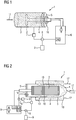
1 einen Rußsensor, -
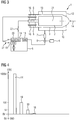
2 einen weiteren Rußsensor, -
3 eine erfindungsgemäßen Rußsensor, der mit dem erfindungsgemäßen Verfahren betrieben werden kann, -
4 beispielhaft die unterschiedlichen elektrischen Potentiale, -
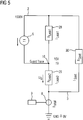
5 ein Ersatzschaltbild des erfindungsgemäßen elektrostatischen Rußsensors, -
6 eine Strom-Zeit-Kurve, die von einem erfindungsgemäßen Rußsensor erzeugt wurde.
-
1 a soot sensor, -
2nd another soot sensor, -
3rd a soot sensor according to the invention which can be operated using the method according to the invention, -
4th the different electrical potentials, for example, -
5 an equivalent circuit diagram of the electrostatic soot sensor according to the invention, -
6 a current-time curve, which was generated by a soot sensor according to the invention.
Weiterhin ist in
Die Spannung, die zwischen der ersten Elektrode
Insbesondere Wasserablagerungen auf der ersten Elektrode
Rußpartikel
Weiterhin zeigt aber
In dem Isolationskörper
Es ist aber auch denkbar eine Strommessung zwischen der ersten Elektrode
Solange der Abgassensor
Nach der Taupunktfreigabe kann die Messphase des Rußsensors
Die Guardelektrode
Vor der Taupunktfreigabe ist die Guardelektrode
Zur Fehlerdiagnose kann der Stromgradient dI/dt im abfallenden Zweig der Normalkurve
Die Fehlerkurve
Claims (4)
Priority Applications (5)
| Application Number | Priority Date | Filing Date | Title |
|---|---|---|---|
| DE102015225745.2A DE102015225745B4 (en) | 2015-12-17 | 2015-12-17 | Electrostatic soot sensor |
| US16/062,798 US10900882B2 (en) | 2015-12-17 | 2016-12-07 | Electrostatic soot sensor |
| PCT/EP2016/080094 WO2017102505A1 (en) | 2015-12-17 | 2016-12-07 | Electrostatic soot sensor |
| EP16809356.5A EP3391024B1 (en) | 2015-12-17 | 2016-12-07 | Electrostatic soot sensor |
| CN201680074179.2A CN108369174A (en) | 2015-12-17 | 2016-12-07 | Electrostatic soot sensor |
Applications Claiming Priority (1)
| Application Number | Priority Date | Filing Date | Title |
|---|---|---|---|
| DE102015225745.2A DE102015225745B4 (en) | 2015-12-17 | 2015-12-17 | Electrostatic soot sensor |
Publications (2)
| Publication Number | Publication Date |
|---|---|
| DE102015225745A1 DE102015225745A1 (en) | 2017-06-22 |
| DE102015225745B4 true DE102015225745B4 (en) | 2020-06-25 |
Family
ID=57539239
Family Applications (1)
| Application Number | Title | Priority Date | Filing Date |
|---|---|---|---|
| DE102015225745.2A Active DE102015225745B4 (en) | 2015-12-17 | 2015-12-17 | Electrostatic soot sensor |
Country Status (5)
| Country | Link |
|---|---|
| US (1) | US10900882B2 (en) |
| EP (1) | EP3391024B1 (en) |
| CN (1) | CN108369174A (en) |
| DE (1) | DE102015225745B4 (en) |
| WO (1) | WO2017102505A1 (en) |
Families Citing this family (5)
| Publication number | Priority date | Publication date | Assignee | Title |
|---|---|---|---|---|
| DE102015225745B4 (en) | 2015-12-17 | 2020-06-25 | Vitesco Technologies GmbH | Electrostatic soot sensor |
| DE112019000725T5 (en) * | 2018-02-08 | 2020-11-05 | Ngk Insulators, Ltd. | Particle detection device |
| FR3081503B1 (en) | 2018-05-28 | 2020-05-15 | Renault S.A.S | SYSTEM AND METHOD FOR ESTIMATING THE QUANTITY OF POLLUTANT PARTICLES IN THE ENGINE OIL OF A DIESEL INTERNAL COMBUSTION ENGINE |
| DE102020205944A1 (en) * | 2020-05-12 | 2021-11-18 | Robert Bosch Gesellschaft mit beschränkter Haftung | Sensor for detecting at least one property of a measurement gas |
| WO2022072753A1 (en) * | 2020-09-30 | 2022-04-07 | Emisense Technologies, Llc | Using variable voltage and current rate of change to measure particulate matter sensors |
Citations (5)
| Publication number | Priority date | Publication date | Assignee | Title |
|---|---|---|---|---|
| DE19536705A1 (en) | 1995-09-30 | 1997-04-03 | Guenther Prof Dr Ing Hauser | Method for measuring particles in gas flow e.g. vehicle exhaust |
| DE102007046099A1 (en) | 2007-09-26 | 2009-04-02 | Robert Bosch Gmbh | Sensor element for detection of sooty particles emitted from vehicle, has supply lines comprising measuring electrode supply line insulation, which surrounds supply lines and is arranged over and/or adjacent and below supply lines |
| DE102007046096A1 (en) | 2007-09-26 | 2009-04-02 | Robert Bosch Gmbh | Method for the self-diagnosis of a particle sensor, suitable particle sensors for carrying out the method and their use |
| DE102010030634A1 (en) | 2010-06-29 | 2011-12-29 | Robert Bosch Gmbh | Method and device for operating a particle sensor |
| DE102010055478A1 (en) | 2010-12-22 | 2012-06-28 | Continental Automotive Gmbh | Method for operating a soot sensor |
Family Cites Families (10)
| Publication number | Priority date | Publication date | Assignee | Title |
|---|---|---|---|---|
| DE3820740A1 (en) * | 1988-06-18 | 1989-12-21 | Bosch Gmbh Robert | COAGULATOR FOR DEVICES FOR PURIFYING EXHAUST GAS FOSSILER FUELS |
| US5662786A (en) * | 1990-03-19 | 1997-09-02 | Robert Bosch Gmbh | Electrochemical sensor |
| JP2698804B2 (en) * | 1995-10-24 | 1998-01-19 | 株式会社オーデン | Diesel engine exhaust particulate collection device by electrical control |
| EP1287242A1 (en) * | 2000-06-01 | 2003-03-05 | Blue Planet Co., Ltd | Apparatus for removing soot and no x? in exhaust gas from diesel engines |
| WO2003095095A1 (en) * | 2002-05-09 | 2003-11-20 | Ohio University | Membrane laminar wet electrostatic precipitator |
| DE102006047780A1 (en) | 2006-10-06 | 2008-04-10 | Endress + Hauser Gmbh + Co. Kg | Device for determining and / or monitoring a process variable |
| US7609068B2 (en) | 2007-10-04 | 2009-10-27 | Delphi Technologies, Inc. | System and method for particulate sensor diagnostic |
| JP5537487B2 (en) | 2011-04-12 | 2014-07-02 | 日本特殊陶業株式会社 | Particle detection system |
| JP5547126B2 (en) * | 2011-05-11 | 2014-07-09 | 日本特殊陶業株式会社 | Particle detection system |
| DE102015225745B4 (en) | 2015-12-17 | 2020-06-25 | Vitesco Technologies GmbH | Electrostatic soot sensor |
-
2015
- 2015-12-17 DE DE102015225745.2A patent/DE102015225745B4/en active Active
-
2016
- 2016-12-07 WO PCT/EP2016/080094 patent/WO2017102505A1/en not_active Ceased
- 2016-12-07 US US16/062,798 patent/US10900882B2/en active Active
- 2016-12-07 CN CN201680074179.2A patent/CN108369174A/en not_active Withdrawn
- 2016-12-07 EP EP16809356.5A patent/EP3391024B1/en active Active
Patent Citations (5)
| Publication number | Priority date | Publication date | Assignee | Title |
|---|---|---|---|---|
| DE19536705A1 (en) | 1995-09-30 | 1997-04-03 | Guenther Prof Dr Ing Hauser | Method for measuring particles in gas flow e.g. vehicle exhaust |
| DE102007046099A1 (en) | 2007-09-26 | 2009-04-02 | Robert Bosch Gmbh | Sensor element for detection of sooty particles emitted from vehicle, has supply lines comprising measuring electrode supply line insulation, which surrounds supply lines and is arranged over and/or adjacent and below supply lines |
| DE102007046096A1 (en) | 2007-09-26 | 2009-04-02 | Robert Bosch Gmbh | Method for the self-diagnosis of a particle sensor, suitable particle sensors for carrying out the method and their use |
| DE102010030634A1 (en) | 2010-06-29 | 2011-12-29 | Robert Bosch Gmbh | Method and device for operating a particle sensor |
| DE102010055478A1 (en) | 2010-12-22 | 2012-06-28 | Continental Automotive Gmbh | Method for operating a soot sensor |
Also Published As
| Publication number | Publication date |
|---|---|
| EP3391024B1 (en) | 2022-04-20 |
| US20200284711A1 (en) | 2020-09-10 |
| EP3391024A1 (en) | 2018-10-24 |
| DE102015225745A1 (en) | 2017-06-22 |
| WO2017102505A1 (en) | 2017-06-22 |
| US10900882B2 (en) | 2021-01-26 |
| CN108369174A (en) | 2018-08-03 |
Similar Documents
| Publication | Publication Date | Title |
|---|---|---|
| DE102015225745B4 (en) | Electrostatic soot sensor | |
| DE102009028239B4 (en) | Method for self-diagnosis of a particle sensor | |
| DE102009033232A1 (en) | Method for the on-vehicle functional diagnosis of a soot sensor and / or for the detection of further constituents in the soot in a motor vehicle | |
| DE102009049669A1 (en) | Method for condition evaluation of a soot sensor in a motor vehicle | |
| DE102014222844B4 (en) | soot sensor | |
| DE102007014761A1 (en) | Method for operating collecting particle sensors, involves providing with measuring phases, during which particle contained in exhaust gas flow is absorbed at measuring section | |
| DE102013223630A1 (en) | Method and device for operating a particle sensor | |
| DE102012210525A1 (en) | Method for functional control of a sensor for detecting particles and sensor for detecting particles | |
| DE102008031648A1 (en) | Method and device for operating a particle sensor | |
| DE102009028319A1 (en) | Particle sensor operating method for function monitoring of diesel particle filters in diesel internal combustion engine of vehicle, involves executing regeneration phases after obtaining triggering threshold or expected threshold | |
| DE102010055478A1 (en) | Method for operating a soot sensor | |
| WO2020030324A1 (en) | Method for operating a sensor for detecting particles in a gas for measurement | |
| DE102015225739B4 (en) | Method of operating an electrostatic soot sensor | |
| DE102011086148A1 (en) | Method for operating resistive sensor in exhaust duct of internal combustion engine e.g. petrol engine, involves determining dew point end in exhaust duct from measured change in conductivity of resistive sensor | |
| WO2016046229A1 (en) | Soot sensor | |
| DE102009046315A1 (en) | Method for operating particle sensor for on-board diagnostics of diesel internal combustion engine, involves directly heating soot particles with heating element, and determining change in conductivity of soot particles or sooth path | |
| DE102014220398A1 (en) | Method for checking the function of a sensor for the detection of particles | |
| DE102015215848B4 (en) | Method for monitoring the function of an electrostatic soot sensor | |
| DE102009000077A1 (en) | Particle sensor for detecting conductive particles in gas flow, has measuring cell and electrode system with one electrode, another electrode and semi-conducting or small conducting material | |
| DE102013216227A1 (en) | Capacitive self-diagnosis of the electrode system of a particle sensor | |
| DE102017202859B4 (en) | Method for operating an electrostatic particle sensor and electrostatic particle sensor | |
| DE102013206092A1 (en) | Method for evaluating the measured values of a soot sensor | |
| DE102018207784A1 (en) | Sensor arrangement for detecting particles of a measuring gas in a measuring gas space and method for detecting particles of a measuring gas in a measuring gas space | |
| DE102016220832A1 (en) | Sensor element for detecting particles of a measuring gas in a measuring gas chamber | |
| DE102018207789A1 (en) | Sensor arrangement for detecting particles of a measuring gas in a measuring gas space and method for detecting particles of a measuring gas in a measuring gas space |
Legal Events
| Date | Code | Title | Description |
|---|---|---|---|
| R012 | Request for examination validly filed | ||
| R016 | Response to examination communication | ||
| R018 | Grant decision by examination section/examining division | ||
| R081 | Change of applicant/patentee |
Owner name: EMISENSE TECHNOLOGIES LLC, LADERA RANCH, US Free format text: FORMER OWNER: CONTINENTAL AUTOMOTIVE GMBH, 30165 HANNOVER, DE Owner name: VITESCO TECHNOLOGIES GMBH, DE Free format text: FORMER OWNER: CONTINENTAL AUTOMOTIVE GMBH, 30165 HANNOVER, DE |
|
| R020 | Patent grant now final | ||
| R081 | Change of applicant/patentee |
Owner name: EMISENSE TECHNOLOGIES LLC, LADERA RANCH, US Free format text: FORMER OWNER: VITESCO TECHNOLOGIES GMBH, 30165 HANNOVER, DE Owner name: VITESCO TECHNOLOGIES GMBH, DE Free format text: FORMER OWNER: VITESCO TECHNOLOGIES GMBH, 30165 HANNOVER, DE |
|
| R081 | Change of applicant/patentee |
Owner name: EMISENSE TECHNOLOGIES LLC, LADERA RANCH, US Free format text: FORMER OWNER: VITESCO TECHNOLOGIES GMBH, 93055 REGENSBURG, DE |
|
| R082 | Change of representative |
Representative=s name: HGF EUROPE LLP, DE |