DE102016108564A1 - lamp bracket - Google Patents
lamp bracket Download PDFInfo
- Publication number
- DE102016108564A1 DE102016108564A1 DE102016108564.2A DE102016108564A DE102016108564A1 DE 102016108564 A1 DE102016108564 A1 DE 102016108564A1 DE 102016108564 A DE102016108564 A DE 102016108564A DE 102016108564 A1 DE102016108564 A1 DE 102016108564A1
- Authority
- DE
- Germany
- Prior art keywords
- condyle
- socket
- joint
- holder
- lamp
- Prior art date
- Legal status (The legal status is an assumption and is not a legal conclusion. Google has not performed a legal analysis and makes no representation as to the accuracy of the status listed.)
- Withdrawn
Links
Images

Classifications
-
- F—MECHANICAL ENGINEERING; LIGHTING; HEATING; WEAPONS; BLASTING
- F21—LIGHTING
- F21V—FUNCTIONAL FEATURES OR DETAILS OF LIGHTING DEVICES OR SYSTEMS THEREOF; STRUCTURAL COMBINATIONS OF LIGHTING DEVICES WITH OTHER ARTICLES, NOT OTHERWISE PROVIDED FOR
- F21V21/00—Supporting, suspending, or attaching arrangements for lighting devices; Hand grips
- F21V21/14—Adjustable mountings
- F21V21/26—Pivoted arms
- F21V21/28—Pivoted arms adjustable in more than one plane
- F21V21/29—Pivoted arms adjustable in more than one plane employing universal joints
-
- B—PERFORMING OPERATIONS; TRANSPORTING
- B62—LAND VEHICLES FOR TRAVELLING OTHERWISE THAN ON RAILS
- B62J—CYCLE SADDLES OR SEATS; AUXILIARY DEVICES OR ACCESSORIES SPECIALLY ADAPTED TO CYCLES AND NOT OTHERWISE PROVIDED FOR, e.g. ARTICLE CARRIERS OR CYCLE PROTECTORS
- B62J6/00—Arrangement of optical signalling or lighting devices on cycles; Mounting or supporting thereof; Circuits therefor
- B62J6/02—Headlights
- B62J6/028—Headlights specially adapted for rider-propelled cycles with or without additional source of power
- B62J6/03—Supporting means therefor, e.g. mounting brackets
-
- A—HUMAN NECESSITIES
- A42—HEADWEAR
- A42B—HATS; HEAD COVERINGS
- A42B3/00—Helmets; Helmet covers ; Other protective head coverings
- A42B3/04—Parts, details or accessories of helmets
- A42B3/0406—Accessories for helmets
- A42B3/0433—Detecting, signalling or lighting devices
- A42B3/044—Lighting devices, e.g. helmets with lamps
Landscapes
- Engineering & Computer Science (AREA)
- General Engineering & Computer Science (AREA)
- Mechanical Engineering (AREA)
- Motorcycle And Bicycle Frame (AREA)
- Lighting Device Outwards From Vehicle And Optical Signal (AREA)
Abstract
Die vorliegende Erfindung betrifft eine Halterung, insbesondere Lampenhalterung mit einem Kugelgelenk, das eine Gelenkpfanne und einen Gelenkkopf besitzt, die in Teilbereichen korrespondierende kugelförmige Gelenkflächen aufweisen, wobei die Gelenkpfanne im zusammengesetzten Zustand den Gelenkkopf über dessen Äquator hinaus umgreift. Um die Vorteile eines Kugelgelenkes und die Vorteile einer lösbaren Befestigung miteinander zu verbinden, wird erfindungsgemäß vorgeschlagen, dass die Gelenkpfanne und der Gelenkkopf durch eine Steck-Dreh-Bewegung lösbar miteinander verbindbar sind, wozu die Gelenkpfanne eine Längsnut besitzt, die die kugelförmigen Gelenkflächen unterbricht und in die der Gelenkkopf einsteckbar ist, so dass sich durch eine anschließende Drehbewegung des Gelenkkopfes relativ zu der Gelenkpfanne eine formschlüssige Lagerung des Gelenkkopfes innerhalb der Gelenkpfanne ergibt.The present invention relates to a holder, in particular lamp holder with a ball joint, which has a joint socket and a condyle, which have corresponding partial spherical surfaces in partial areas, the socket in the assembled state surrounds the condyle over its equator addition. In order to combine the advantages of a ball joint and the advantages of a releasable attachment to each other, the invention proposes that the joint socket and the condyle are releasably connected to each other by a plug-in rotary movement, including the joint socket has a longitudinal groove which interrupts the spherical joint surfaces and in which the condyle is plugged, so that results in a positive rotation of the condyle relative to the socket a positive storage of the condyle within the socket.
Description
Die vorliegende Erfindung bezieht sich auf eine Halterung, insbesondere eine Lampenhalterung, mit einem Kugelgelenk, das eine Gelenkpfanne und einen Gelenkkopf besitzt, die in Teilbereichen korrespondierende kugelförmige Gelenkflächen aufweisen, wobei die Gelenkpfanne im zusammengesetzten Zustand den Gelenkkopf über dessen Äquator hinaus umgreift. The present invention relates to a holder, in particular a lamp holder, with a ball joint, which has a joint socket and a condyle, which have corresponding partial spherical surfaces in partial areas, wherein the socket in the assembled state surrounds the condyle over the equator out.
Derartige Halterungen sind aus dem Stand der Technik bekannt und erlauben eine stufenlose Ausrichtung einer Lampe innerhalb eines vorgegebenen Raumwinkels, dessen Größe von der Öffnung der Gelenkpfanne und der Form des Gelenkkopfes bzw. der hieran angeordneten Lampe abhängt. Konstruktionsbedingt lassen sich herkömmliche Lampenhalterungen mit einem Kugelgelenk, dessen Gelenkpfanne den Gelenkkopf über dessen Äquator hinaus umgreift (sog. Nussgelenk), nicht ohne Weiteres auseinandernehmen, weil die Gelenkpfanne den Gelenkkopf vollständig formschlüssig umgreift. Aus diesen Gründen werden Kugelgelenke, insbesondere Nussgelenke, nicht für die lösbare Befestigungen von Lampen eingesetzt. Auf die besonderen Vorteile von Kugelgelenken hinsichtlich der freien und stufenlosen Ausrichtbarkeit der Lampe wird in diesen Fällen verzichtet. Such brackets are known from the prior art and allow a continuous alignment of a lamp within a predetermined solid angle, the size of which depends on the opening of the socket and the shape of the condyle or the lamp arranged thereon. Due to the design, conventional lamp holders with a ball joint, whose socket surrounds the condyle beyond its equator (so-called nut joint), can not be disassembled without further ado, because the joint socket engages around the condyle completely in a form-fitting manner. For these reasons, ball joints, especially nut joints, are not used for the detachable fixtures of lamps. The particular advantages of ball joints with respect to the free and stepless adjustability of the lamp is dispensed with in these cases.
Es ist daher die Aufgabe der vorliegenden Erfindung, eine Halterung für eine Lampe anzugeben, die die Vorteile eines Kugelgelenkes bei der Ausrichtung der Lampe mit den Vorteilen einer lösbaren Befestigung kombiniert. It is therefore the object of the present invention to provide a holder for a lamp, which combines the advantages of a ball joint in the alignment of the lamp with the advantages of a releasable attachment.
Diese Aufgabe wird durch die Halterung nach Anspruch 1 gelöst. Erfindungsgemäß sind die Gelenkpfanne und der Gelenkkopf durch eine Steck-Dreh-Bewegung lösbar miteinander verbindbar, wozu die Gelenkpfanne eine Längsnut besitzt, die die kugelförmigen Gelenkflächen unterbricht und in die der Gelenkkopf einsteckbar ist, so dass sich durch eine anschließende Drehbewegung des Gelenkkopfes relativ zu der Gelenkpfanne eine formschlüssige Lagerung des Gelenkkopfes innerhalb der Gelenkpfanne ergibt. This object is achieved by the holder according to
Im zusammengesetzten Zustand lässt sich die Halterung in azimutaler Richtung (d. h. entlang des Äquators) über einen Raumwinkel von mindestens 90° bewegen, ohne dass die Längsnut die Befestigung der Halterung innerhalb der Gelenkpfanne beeinträchtigt und/oder einschränkt. In polarer Richtung ist die Bewegungsfreiheit der Halterung aufgrund der vorhandenen Längsnut nicht eingeschränkt. Insofern ist die lösbare Halterung insbesondere für solche Lampen vorteilhaft, die eine stabile und gleichzeitig lösbare Befestigung benötigen und bei denen eine azimutale Verstellung von ca. 90° ausreicht. Insbesondere für Fahrradlampe, die am Lenker eines Fahrrads oder auf einem Helm befestigt werden, hat sich die erfindungsgemäße Halterung als besonders vorteilhaft erwiesen. In the assembled state, the support can be moved in the azimuthal direction (i.e., along the equator) through a solid angle of at least 90 ° without the longitudinal groove interfering with and / or restricting attachment of the support within the socket. In the polar direction, the freedom of movement of the holder is not limited due to the existing longitudinal groove. In this respect, the detachable mounting is particularly advantageous for lamps that require a stable and simultaneously releasable attachment and in which an azimuthal adjustment of about 90 ° sufficient. In particular, for bicycle lamp, which are attached to the handlebars of a bicycle or on a helmet, the holder according to the invention has proven to be particularly advantageous.
Bevorzugte Ausgestaltungen werden nachfolgend sowie in den Unteransprüchen angegeben. Preferred embodiments are given below and in the subclaims.
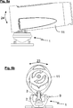
Nach einer ersten bevorzugten Ausführungsform der Erfindung ist vorgesehen, dass der Gelenkkopf zwei beabstandete Führungsflächen aufweist, die durch die kugelförmigen Gelenkflächen des Gelenkkopfes miteinander verbunden sind. Die Führungsflächen sind parallel zueinander ausgerichtet und soweit voneinander beabstandet, dass der Gelenkkopf vollständig in die Längsnut der Gelenkpfanne eingesteckt werden kann. Insofern ist die Breite des Gelenkkopfes und mithin der Abstand der Führungsflächen kleiner als die Breite der Längsnut, die innerhalb der Gelenkpfanne eingearbeitet ist. According to a first preferred embodiment of the invention it is provided that the joint head has two spaced guide surfaces, which are interconnected by the spherical joint surfaces of the joint head. The guide surfaces are aligned parallel to each other and so far apart that the joint head can be completely inserted into the longitudinal groove of the socket. In this respect, the width of the condyle and thus the distance of the guide surfaces is smaller than the width of the longitudinal groove which is incorporated within the socket.
Vorzugsweise ist der Gelenkkopf von einer Schraube zur lösbaren Befestigung einer Lampe durchgriffen. Der Gelenkkopf besitzt zudem mindestens ein Führungselement, das eine relative Verschiebung zwischen der montierten Lampe und dem Gelenkkopf im zusammengesetzten Zustand verhindert. Preferably, the condyle is penetrated by a screw for releasably securing a lamp. The joint head also has at least one guide element which prevents a relative displacement between the mounted lamp and the condyle in the assembled state.
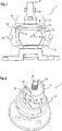
Nach einer weiterhin bevorzugten Ausgestaltung der Erfindung ist vorgesehen, dass die Gelenkpfanne ein Befestigungselement besitzt, das vorzugsweise mit einem Helm oder einem Fahrradlenker verbindbar ist. Ein solches Befestigungselement kann in Form einer Platte ausgestaltet sein, die mit einer Schnellspanneinrichtung oder mit Kabelbindern an einem Helm oder an einem Fahrradlenker befestigt wird. According to a further preferred embodiment of the invention it is provided that the socket has a fastener, which is preferably connectable to a helmet or a bicycle handlebar. Such a fastening element may be designed in the form of a plate which is fastened with a quick-release device or with cable ties to a helmet or to a bicycle handlebar.
Schließlich ist nach einer weiteren bevorzugten Ausgestaltung der Erfindung vorgesehen, dass die Gelenkpfanne aus zwei schalenförmigen Teilbereichen besteht, die von einem Sprengring zusammengehalten sind. Finally, according to a further preferred embodiment of the invention, it is provided that the joint socket consists of two shell-shaped subregions which are held together by a snap ring.
Konkrete Ausgestaltungen der vorliegenden Erfindung werden nachfolgend anhand der Abbildungen erläutert. Es zeigen: Concrete embodiments of the present invention will be explained below with reference to the drawings. Show it:
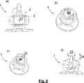
Schließlich zeigt die Bildfolge der
Anschließend wird der Gelenkkopf
Claims (5)
Priority Applications (3)
| Application Number | Priority Date | Filing Date | Title |
|---|---|---|---|
| DE102016108564.2A DE102016108564A1 (en) | 2016-05-10 | 2016-05-10 | lamp bracket |
| PCT/DE2017/100382 WO2017194052A1 (en) | 2016-05-10 | 2017-05-04 | Lamp holder |
| EP17733959.5A EP3455552B1 (en) | 2016-05-10 | 2017-05-04 | Lamp holder |
Applications Claiming Priority (1)
| Application Number | Priority Date | Filing Date | Title |
|---|---|---|---|
| DE102016108564.2A DE102016108564A1 (en) | 2016-05-10 | 2016-05-10 | lamp bracket |
Publications (1)
| Publication Number | Publication Date |
|---|---|
| DE102016108564A1 true DE102016108564A1 (en) | 2017-11-16 |
Family
ID=59253322
Family Applications (1)
| Application Number | Title | Priority Date | Filing Date |
|---|---|---|---|
| DE102016108564.2A Withdrawn DE102016108564A1 (en) | 2016-05-10 | 2016-05-10 | lamp bracket |
Country Status (3)
| Country | Link |
|---|---|
| EP (1) | EP3455552B1 (en) |
| DE (1) | DE102016108564A1 (en) |
| WO (1) | WO2017194052A1 (en) |
Families Citing this family (1)
| Publication number | Priority date | Publication date | Assignee | Title |
|---|---|---|---|---|
| CN110286524B (en) * | 2019-06-28 | 2021-10-29 | 厦门天马微电子有限公司 | Display module and display device |
Family Cites Families (5)
| Publication number | Priority date | Publication date | Assignee | Title |
|---|---|---|---|---|
| US1186428A (en) * | 1915-11-12 | 1916-06-06 | Harold John Newman | Electric-light bracket. |
| CH549260A (en) * | 1973-05-04 | 1974-05-15 | Baitella Carlo | TRIPOD, IN PARTICULAR FOR LEVER GAUGE. |
| US4898490A (en) * | 1988-02-19 | 1990-02-06 | Syron Engineering And Manufacturing Corporation | Structure formed from ball jointed links |
| US6951409B2 (en) * | 2003-08-29 | 2005-10-04 | Chih-Ching Hsien | Lamp assembly attached on a hand tool |
| TWM495255U (en) * | 2014-10-31 | 2015-02-11 | Jin-Lin Cai | Lighting device for gas burner |
-
2016
- 2016-05-10 DE DE102016108564.2A patent/DE102016108564A1/en not_active Withdrawn
-
2017
- 2017-05-04 WO PCT/DE2017/100382 patent/WO2017194052A1/en not_active Ceased
- 2017-05-04 EP EP17733959.5A patent/EP3455552B1/en active Active
Also Published As
| Publication number | Publication date |
|---|---|
| WO2017194052A1 (en) | 2017-11-16 |
| EP3455552A1 (en) | 2019-03-20 |
| EP3455552B1 (en) | 2020-04-15 |
Similar Documents
| Publication | Publication Date | Title |
|---|---|---|
| AT394250B (en) | CROSS-CONNECTOR FOR TWO CROSSING PIPES | |
| DE69017669T2 (en) | Clamping device for flashlight holder. | |
| EP0297033A2 (en) | Fixing element for a rod | |
| DE202005001986U1 (en) | Universal joint arrangement between a device holder and a support arm or a console | |
| DE202009013592U1 (en) | Handlebar stem for bicycle handlebars | |
| DE102007049513B4 (en) | compasses | |
| EP1646300A1 (en) | System for fixing in position collapsible construction kits | |
| DE4336282A1 (en) | Connecting element for two intersecting tubes | |
| DE202016102480U1 (en) | lamp bracket | |
| EP3455552B1 (en) | Lamp holder | |
| EP1939519B1 (en) | Tripod | |
| DE8703940U1 (en) | Articulated connection for pipes | |
| DE102010025978A1 (en) | Tripod head arrangement for supporting and/or positioning camera, has camera indirectly attached with multi-element supporting device, and supporting elements pivotable in respective use position against magnification of pivoting angle | |
| DE202015003640U1 (en) | Remote optical device with a holder for a belt | |
| DE10145199B4 (en) | Cardanic suspension device for a camera balance device | |
| DE202006002876U1 (en) | Device for adjusting of especially window frame in aperture has bolt axially movable in sleeve provided with wings which have locking element so that sleeve in fixed position is connected to component with locking action | |
| DE4342882C1 (en) | Adjusting arrangement for one or more reflectors for a motor-vehicle headlight unit (headlamp unit) | |
| DE10155822B4 (en) | Adjustable handlebar stem for two-wheeled vehicles | |
| EP1536737A1 (en) | Ball joint for a device used for accelerating jaw growth | |
| DE3437089A1 (en) | Clamping device | |
| DE3207981A1 (en) | Shower head | |
| DE102004063371B4 (en) | Conga Stand | |
| DE20118764U1 (en) | Schwenkretraktor | |
| EP2017484B1 (en) | Connecting device | |
| DE9104102U1 (en) | Mounting device for the surface reflector of a satellite antenna |
Legal Events
| Date | Code | Title | Description |
|---|---|---|---|
| R163 | Identified publications notified | ||
| R081 | Change of applicant/patentee |
Owner name: LEDLENSER GMBH & CO. KG, DE Free format text: FORMER OWNER: ZWEIBRUEDER OPTOELECTRONICS GMBH & CO. KG, 42699 SOLINGEN, DE |
|
| R082 | Change of representative |
Representative=s name: PATENTANWAELTE VOMBERG & SCHART, DE |
|
| R119 | Application deemed withdrawn, or ip right lapsed, due to non-payment of renewal fee |