DE102017123721A1 - Process for the production of fiber-reinforced plastic molded parts - Google Patents
Process for the production of fiber-reinforced plastic molded parts Download PDFInfo
- Publication number
- DE102017123721A1 DE102017123721A1 DE102017123721.6A DE102017123721A DE102017123721A1 DE 102017123721 A1 DE102017123721 A1 DE 102017123721A1 DE 102017123721 A DE102017123721 A DE 102017123721A DE 102017123721 A1 DE102017123721 A1 DE 102017123721A1
- Authority
- DE
- Germany
- Prior art keywords
- fiber
- screw
- during
- injection
- cylinder
- Prior art date
- Legal status (The legal status is an assumption and is not a legal conclusion. Google has not performed a legal analysis and makes no representation as to the accuracy of the status listed.)
- Withdrawn
Links
Images


Classifications
-
- B—PERFORMING OPERATIONS; TRANSPORTING
- B29—WORKING OF PLASTICS; WORKING OF SUBSTANCES IN A PLASTIC STATE IN GENERAL
- B29C—SHAPING OR JOINING OF PLASTICS; SHAPING OF MATERIAL IN A PLASTIC STATE, NOT OTHERWISE PROVIDED FOR; AFTER-TREATMENT OF THE SHAPED PRODUCTS, e.g. REPAIRING
- B29C45/00—Injection moulding, i.e. forcing the required volume of moulding material through a nozzle into a closed mould; Apparatus therefor
- B29C45/17—Component parts, details or accessories; Auxiliary operations
- B29C45/46—Means for plasticising or homogenising the moulding material or forcing it into the mould
- B29C45/58—Details
- B29C45/60—Screws
-
- B—PERFORMING OPERATIONS; TRANSPORTING
- B29—WORKING OF PLASTICS; WORKING OF SUBSTANCES IN A PLASTIC STATE IN GENERAL
- B29B—PREPARATION OR PRETREATMENT OF THE MATERIAL TO BE SHAPED; MAKING GRANULES OR PREFORMS; RECOVERY OF PLASTICS OR OTHER CONSTITUENTS OF WASTE MATERIAL CONTAINING PLASTICS
- B29B7/00—Mixing; Kneading
- B29B7/80—Component parts, details or accessories; Auxiliary operations
- B29B7/88—Adding charges, i.e. additives
- B29B7/90—Fillers or reinforcements, e.g. fibres
-
- B—PERFORMING OPERATIONS; TRANSPORTING
- B29—WORKING OF PLASTICS; WORKING OF SUBSTANCES IN A PLASTIC STATE IN GENERAL
- B29B—PREPARATION OR PRETREATMENT OF THE MATERIAL TO BE SHAPED; MAKING GRANULES OR PREFORMS; RECOVERY OF PLASTICS OR OTHER CONSTITUENTS OF WASTE MATERIAL CONTAINING PLASTICS
- B29B7/00—Mixing; Kneading
- B29B7/80—Component parts, details or accessories; Auxiliary operations
- B29B7/88—Adding charges, i.e. additives
- B29B7/90—Fillers or reinforcements, e.g. fibres
- B29B7/905—Fillers or reinforcements, e.g. fibres with means for pretreatment of the charges or fibres
-
- B—PERFORMING OPERATIONS; TRANSPORTING
- B29—WORKING OF PLASTICS; WORKING OF SUBSTANCES IN A PLASTIC STATE IN GENERAL
- B29C—SHAPING OR JOINING OF PLASTICS; SHAPING OF MATERIAL IN A PLASTIC STATE, NOT OTHERWISE PROVIDED FOR; AFTER-TREATMENT OF THE SHAPED PRODUCTS, e.g. REPAIRING
- B29C45/00—Injection moulding, i.e. forcing the required volume of moulding material through a nozzle into a closed mould; Apparatus therefor
- B29C45/17—Component parts, details or accessories; Auxiliary operations
- B29C45/18—Feeding the material into the injection moulding apparatus, i.e. feeding the non-plastified material into the injection unit
- B29C45/1816—Feeding auxiliary material, e.g. colouring material
-
- B—PERFORMING OPERATIONS; TRANSPORTING
- B29—WORKING OF PLASTICS; WORKING OF SUBSTANCES IN A PLASTIC STATE IN GENERAL
- B29C—SHAPING OR JOINING OF PLASTICS; SHAPING OF MATERIAL IN A PLASTIC STATE, NOT OTHERWISE PROVIDED FOR; AFTER-TREATMENT OF THE SHAPED PRODUCTS, e.g. REPAIRING
- B29C45/00—Injection moulding, i.e. forcing the required volume of moulding material through a nozzle into a closed mould; Apparatus therefor
- B29C45/17—Component parts, details or accessories; Auxiliary operations
- B29C45/46—Means for plasticising or homogenising the moulding material or forcing it into the mould
- B29C45/47—Means for plasticising or homogenising the moulding material or forcing it into the mould using screws
- B29C45/50—Axially movable screw
-
- B—PERFORMING OPERATIONS; TRANSPORTING
- B29—WORKING OF PLASTICS; WORKING OF SUBSTANCES IN A PLASTIC STATE IN GENERAL
- B29C—SHAPING OR JOINING OF PLASTICS; SHAPING OF MATERIAL IN A PLASTIC STATE, NOT OTHERWISE PROVIDED FOR; AFTER-TREATMENT OF THE SHAPED PRODUCTS, e.g. REPAIRING
- B29C48/00—Extrusion moulding, i.e. expressing the moulding material through a die or nozzle which imparts the desired form; Apparatus therefor
- B29C48/25—Component parts, details or accessories; Auxiliary operations
- B29C48/285—Feeding the extrusion material to the extruder
- B29C48/286—Raw material dosing
-
- B—PERFORMING OPERATIONS; TRANSPORTING
- B29—WORKING OF PLASTICS; WORKING OF SUBSTANCES IN A PLASTIC STATE IN GENERAL
- B29C—SHAPING OR JOINING OF PLASTICS; SHAPING OF MATERIAL IN A PLASTIC STATE, NOT OTHERWISE PROVIDED FOR; AFTER-TREATMENT OF THE SHAPED PRODUCTS, e.g. REPAIRING
- B29C48/00—Extrusion moulding, i.e. expressing the moulding material through a die or nozzle which imparts the desired form; Apparatus therefor
- B29C48/25—Component parts, details or accessories; Auxiliary operations
- B29C48/285—Feeding the extrusion material to the extruder
- B29C48/288—Feeding the extrusion material to the extruder in solid form, e.g. powder or granules
-
- B—PERFORMING OPERATIONS; TRANSPORTING
- B29—WORKING OF PLASTICS; WORKING OF SUBSTANCES IN A PLASTIC STATE IN GENERAL
- B29C—SHAPING OR JOINING OF PLASTICS; SHAPING OF MATERIAL IN A PLASTIC STATE, NOT OTHERWISE PROVIDED FOR; AFTER-TREATMENT OF THE SHAPED PRODUCTS, e.g. REPAIRING
- B29C48/00—Extrusion moulding, i.e. expressing the moulding material through a die or nozzle which imparts the desired form; Apparatus therefor
- B29C48/25—Component parts, details or accessories; Auxiliary operations
- B29C48/285—Feeding the extrusion material to the extruder
- B29C48/288—Feeding the extrusion material to the extruder in solid form, e.g. powder or granules
- B29C48/2886—Feeding the extrusion material to the extruder in solid form, e.g. powder or granules of fillers or of fibrous materials, e.g. short-fibre reinforcements
-
- B—PERFORMING OPERATIONS; TRANSPORTING
- B29—WORKING OF PLASTICS; WORKING OF SUBSTANCES IN A PLASTIC STATE IN GENERAL
- B29C—SHAPING OR JOINING OF PLASTICS; SHAPING OF MATERIAL IN A PLASTIC STATE, NOT OTHERWISE PROVIDED FOR; AFTER-TREATMENT OF THE SHAPED PRODUCTS, e.g. REPAIRING
- B29C48/00—Extrusion moulding, i.e. expressing the moulding material through a die or nozzle which imparts the desired form; Apparatus therefor
- B29C48/25—Component parts, details or accessories; Auxiliary operations
- B29C48/285—Feeding the extrusion material to the extruder
- B29C48/297—Feeding the extrusion material to the extruder at several locations, e.g. using several hoppers or using a separate additive feeding
-
- B—PERFORMING OPERATIONS; TRANSPORTING
- B29—WORKING OF PLASTICS; WORKING OF SUBSTANCES IN A PLASTIC STATE IN GENERAL
- B29C—SHAPING OR JOINING OF PLASTICS; SHAPING OF MATERIAL IN A PLASTIC STATE, NOT OTHERWISE PROVIDED FOR; AFTER-TREATMENT OF THE SHAPED PRODUCTS, e.g. REPAIRING
- B29C48/00—Extrusion moulding, i.e. expressing the moulding material through a die or nozzle which imparts the desired form; Apparatus therefor
- B29C48/25—Component parts, details or accessories; Auxiliary operations
- B29C48/36—Means for plasticising or homogenising the moulding material or forcing it through the nozzle or die
- B29C48/395—Means for plasticising or homogenising the moulding material or forcing it through the nozzle or die using screws surrounded by a cooperating barrel, e.g. single screw extruders
- B29C48/397—Means for plasticising or homogenising the moulding material or forcing it through the nozzle or die using screws surrounded by a cooperating barrel, e.g. single screw extruders using a single screw
-
- B—PERFORMING OPERATIONS; TRANSPORTING
- B29—WORKING OF PLASTICS; WORKING OF SUBSTANCES IN A PLASTIC STATE IN GENERAL
- B29C—SHAPING OR JOINING OF PLASTICS; SHAPING OF MATERIAL IN A PLASTIC STATE, NOT OTHERWISE PROVIDED FOR; AFTER-TREATMENT OF THE SHAPED PRODUCTS, e.g. REPAIRING
- B29C48/00—Extrusion moulding, i.e. expressing the moulding material through a die or nozzle which imparts the desired form; Apparatus therefor
- B29C48/25—Component parts, details or accessories; Auxiliary operations
- B29C48/36—Means for plasticising or homogenising the moulding material or forcing it through the nozzle or die
- B29C48/50—Details of extruders
- B29C48/505—Screws
- B29C48/53—Screws having a varying channel depth, e.g. varying the diameter of the longitudinal screw trunk
-
- B—PERFORMING OPERATIONS; TRANSPORTING
- B29—WORKING OF PLASTICS; WORKING OF SUBSTANCES IN A PLASTIC STATE IN GENERAL
- B29C—SHAPING OR JOINING OF PLASTICS; SHAPING OF MATERIAL IN A PLASTIC STATE, NOT OTHERWISE PROVIDED FOR; AFTER-TREATMENT OF THE SHAPED PRODUCTS, e.g. REPAIRING
- B29C48/00—Extrusion moulding, i.e. expressing the moulding material through a die or nozzle which imparts the desired form; Apparatus therefor
- B29C48/25—Component parts, details or accessories; Auxiliary operations
- B29C48/36—Means for plasticising or homogenising the moulding material or forcing it through the nozzle or die
- B29C48/50—Details of extruders
- B29C48/505—Screws
- B29C48/67—Screws having incorporated mixing devices not provided for in groups B29C48/52 - B29C48/66
-
- B—PERFORMING OPERATIONS; TRANSPORTING
- B29—WORKING OF PLASTICS; WORKING OF SUBSTANCES IN A PLASTIC STATE IN GENERAL
- B29B—PREPARATION OR PRETREATMENT OF THE MATERIAL TO BE SHAPED; MAKING GRANULES OR PREFORMS; RECOVERY OF PLASTICS OR OTHER CONSTITUENTS OF WASTE MATERIAL CONTAINING PLASTICS
- B29B7/00—Mixing; Kneading
- B29B7/30—Mixing; Kneading continuous, with mechanical mixing or kneading devices
- B29B7/34—Mixing; Kneading continuous, with mechanical mixing or kneading devices with movable mixing or kneading devices
- B29B7/38—Mixing; Kneading continuous, with mechanical mixing or kneading devices with movable mixing or kneading devices rotary
- B29B7/40—Mixing; Kneading continuous, with mechanical mixing or kneading devices with movable mixing or kneading devices rotary with single shaft
- B29B7/42—Mixing; Kneading continuous, with mechanical mixing or kneading devices with movable mixing or kneading devices rotary with single shaft with screw or helix
-
- B—PERFORMING OPERATIONS; TRANSPORTING
- B29—WORKING OF PLASTICS; WORKING OF SUBSTANCES IN A PLASTIC STATE IN GENERAL
- B29B—PREPARATION OR PRETREATMENT OF THE MATERIAL TO BE SHAPED; MAKING GRANULES OR PREFORMS; RECOVERY OF PLASTICS OR OTHER CONSTITUENTS OF WASTE MATERIAL CONTAINING PLASTICS
- B29B7/00—Mixing; Kneading
- B29B7/30—Mixing; Kneading continuous, with mechanical mixing or kneading devices
- B29B7/58—Component parts, details or accessories; Auxiliary operations
- B29B7/60—Component parts, details or accessories; Auxiliary operations for feeding, e.g. end guides for the incoming material
- B29B7/603—Component parts, details or accessories; Auxiliary operations for feeding, e.g. end guides for the incoming material in measured doses, e.g. proportioning of several materials
Landscapes
- Engineering & Computer Science (AREA)
- Mechanical Engineering (AREA)
- Manufacturing & Machinery (AREA)
- Injection Moulding Of Plastics Or The Like (AREA)
Abstract
Beschrieben wird ein Verfahren zur Herstellung von faserverstärkten Kunststoff-Formteilen, wobei Endlosfaserstränge (10a, 10b,...) oder geschnittene Glasfaserstränge einer Plastifiziereinheit (3) zugeführt werden. Die Plastifiziereinheit (3) weist einen Zylinder (4) und in dem Zylinder (4) eine dreh- und linearantreibbare Schnecke (5) auf. Über eine erste Öffnung (8) in dem Zylinder (4) wird ein aufzuschmelzendes Kunststoffmaterial eingegeben. Förderabseitig von der ersten Öffnung (8) werden über eine zweite Öffnung (9) die Endlosfaserstränge (10a, 10b,...) oder die geschnittenen Glasfaserstränge in den Zylinder (4) eingegeben und von der Schnecke (5) durch Rotation eingezogen. Aufgeschmolzenes und mit Fasermaterial versetztes Kunststoffmaterial wird durch einen Einspritzhub der Schnecke in ein Formwerkzeug (2) eingespritzt. Zur Verbesserung der Homogenität der Faserkonzentration in den Schneckengängen und somit auch im Formwerkzeug ist erfindungsgemäß vorgesehen, dass die Schnecke (5) während der Ausführung des Einspritzhubs drehangetrieben wird und gleichzeitig Endlosfaserstränge oder geschnittene Glasfaserstränge in die Schneckengänge eingezogen werden.

Description
Die Erfindung betrifft ein Verfahren zur Herstellung von faserverstärkten Kunststoff-Formteilen gemäß dem Oberbegriff von Patentanspruch 1.The invention relates to a method for producing fiber-reinforced plastic molded parts according to the preamble of patent claim 1.
Die
Aus der
Um eine inhomogene Faserkonzentration in gewissem Maße auszugleichen, kann die eingesetzte Schneckenwelle wahlweise eine oder mehrere Mischzonen aufweisen oder sehr lang ausgeführt werden, sodass eine überproportional hohe, schneckengebundene konvektive Mischwirkung entsteht. Auch eine Kombination aus langer Schneckenwelle und Mischzone ist denkbar. Der Nachteil dieser beiden Möglichkeiten besteht in erhöhten Herstellkosten einer verlängerten Plastifiziereinheit und der verstärkten Faserlängenverkürzung die mit Mischoperationen einhergeht.In order to compensate for an inhomogeneous fiber concentration to some extent, the screw shaft used can optionally have one or more mixing zones or be carried out very long, so that a disproportionately high, spiral-bound convective mixing effect arises. A combination of long worm shaft and mixing zone is conceivable. The disadvantage of these two possibilities is increased production costs of an extended plasticizing unit and the increased shortening of the fiber length associated with mixing operations.
Ausgehend hiervon liegt der Erfindung die Aufgabe zugrunde, ein Verfahren anzugeben, mit welchem faserverstärkte Kunststoff-Formteile auf einer mit einer Einschnecken-Plastifiziereinheit ausgestatteten Spritzgießmaschine hergestellt werden können, wobei die spritzgegossenen Kunststoff-Formteile eine verbesserte Homogenität der Faserkonzentration und infolgedessen auch verbesserte mechanische Eigenschaften aufweisen. Eine weitere der Erfindung zugrundeliegende Aufgabe liegt darin, eine höhere Prozessstabilität durch reproduzierbare Plastifizierzeiten zu erzielen.Proceeding from this, the object of the invention is to specify a method with which fiber-reinforced plastic molded parts can be produced on an injection molding machine equipped with a single-screw plasticizing unit, wherein the injection-molded plastic molded parts have improved homogeneity of the fiber concentration and, consequently, improved mechanical properties , Another object of the invention is to achieve a higher process stability through reproducible plasticizing times.
Diese Lösung erfolgt durch ein Verfahren mit den Merkmalen von Anspruch 1. Vorteilhafte Ausgestaltungen und Weiterentwicklungen finden sich in den abhängigen Ansprüchen.This solution is achieved by a method having the features of claim 1. Advantageous embodiments and further developments can be found in the dependent claims.
Dadurch, dass die Schnecke auch während der Ausführung des Einspritzhubs drehangetrieben wird, wobei Endlosfaserstränge oder geschnittene Faserstrangabschnitte in die Schneckengänge eingezogen werden. lassen sich Schwankungen in der Faserkonzentration in der Schmelze und damit auch im spritzgegossenen Kunststoff-Formteil vermeiden. Es kann auf ein distributiv wirkendes Mischteil verzichtet werden. Ein dispersiv wirkendes Mischteil kann vorgesehen sein, um gegebenenfalls auftretende Agglomerate auflösen zu können.Characterized in that the screw is also rotated during the execution of the injection stroke, wherein endless fiber strands or cut fiber strand sections are drawn into the screw threads. Fluctuations in the fiber concentration in the melt and thus also in the injection-molded plastic molded part can be avoided. It can be dispensed with a distributive acting mixing part. A dispersively acting mixing part can be provided in order to dissolve any agglomerates that may occur.
Außerdem kann anstelle einer Schnecke mit einer relativ langen Meteringzone zwecks Homogenisierung der Faserkonzentration für das erfindungsgemäße Verfahren eine Schnecke mit einer demgegenüber kürzer ausgebildeten Meteringzone verwendet werden, was sich in einer Reduzierung der Kosten für die Schnecke bemerkbar macht. Das gilt unabhängig davon, ob ein Mischteil vorhanden ist oder nicht.Moreover, instead of a screw with a relatively long metering zone for the purpose of homogenizing the fiber concentration for the method according to the invention, a screw having a metering zone which is shorter in comparison can be used, which results in a reduction of the costs for the screw. This applies regardless of whether a mixing part is present or not.
Es ergibt sich eine verbesserte Homogenität der Faserkonzentration und infolgedessen liegen auch verbesserte mechanische Eigenschaften im Formteil vor. Zudem kann eine höhere Prozessstabilität durch reproduzierbare Plastifizierzeiten erzielt werden. Das Fasermaterial kann in Form von Endlosfasersträngen zugeführt werden. Es können aber auch geschnittene Faserstrangabschnitte, vorzugsweise geschnittene Glasfaserstränge, als Fasermaterial verwendet werden.This results in an improved homogeneity of the fiber concentration and, as a result, improved mechanical properties are also present in the molded part. In addition, a higher process stability can be achieved by reproducible plasticizing times. The fiber material can be in the form of endless fiber strands be supplied. However, it is also possible to use cut fiber strand sections, preferably cut glass fiber strands, as fiber material.
Gemäß einer bevorzugten Ausführungsform kann die Schneckendrehzahl während der Ausführung des Einspritzhubs derart geregelt werden, dass der Fasergehalt in den Schneckengängen konstant gehalten wird.According to a preferred embodiment, during the execution of the injection stroke, the screw speed can be controlled in such a way that the fiber content in the screw flights is kept constant.
Dabei kann die Schneckendrehzahl vorzugsweise gemäß folgender Formel bestimmt bzw. geregelt werden:
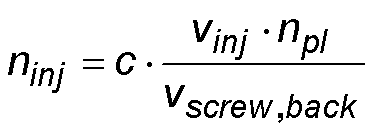
- c:
- Proportionalitätsfaktor, empirisch ermittelt oder aus Schneckengeometrie berechnet.
- ninj:
- Drehzahl während des Einspritzens
- vinj:
- Einspritzgeschwindigkeit
- npl:
- Schneckendrehzahl während des Plastifizierens
- c:
- Proportionality factor, empirically determined or calculated from screw geometry.
- n inj :
- Speed during injection
- v inj :
- Injection speed
- n pl :
- Screw speed during plasticizing
Gemäß einer Weiterbildung der Erfindung kann vorgesehen werden, dass die Granulateindosierung während der Ausführung des Einspritzhubs und/oder während der Nachdruckphase unterbrochen wird.According to one embodiment of the invention can be provided that the Granuleindosierung is interrupted during the execution of the injection stroke and / or during the holding pressure phase.
Die Schneckendrehzahl (ninj.) kann während eines Einspritzhubs verschiedene Werte annehmen.The screw speed (n inj .) May take on different values during an injection stroke.
Das aufzuschmelzende Kunststoffmaterial kann vorzugsweise als Granulat eingegeben werden, wobei die Eingabe des Granulats als Granulateindosierung in die erste Öffnung mit einem gravimetrisch oder volumetrisch betriebenen Granulatdosiergerät erfolgen kann.The plastic material to be melted can preferably be entered as granules, wherein the input of the granules can be done as Granuleindosierung in the first opening with a gravimetrically or volumetrically operated Granulatdosiergerät.
Die Granulateindosierung kann während der Ausführung des Einspritzhubs und/oder während der Nachdruckphase unterbrochen werden.The granule dosage can be interrupted during the execution of the injection stroke and / or during the holding pressure phase.
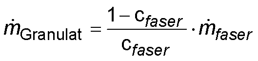
Vorzugsweise kann der Granulatmassestrom dmGranulat/dt, der während des Einspritzens in die Schneckengänge eindosiert werden soll, gemäß folgender Formel bestimmt bzw. geregelt werden, d.h. für die Granulateindosierung kann folgende Formel zugrunde gelegt werden:

- cfaser:
- Gewünschter Fasergehalt im Bauteil
- ṁfaser :
- Fasermassestrom während des Einspritzens (Bekannt, da durch Faserzuführvorrichtung aufgeprägt)
- c fiber :
- Desired fiber content in the component
- ṁ fiber :
- Fiber mass flow during injection (Known as imprinted by fiber feeder)
Nachfolgend soll die Erfindung anhand eines Ausführungsbeispiels und unter Bezugnahme auf die
Die in der
Die
Erfindungsgemäß ist nun vorgesehen, dass die Einschnecken-Plastifiziereinheit in der Weise betrieben wird, dass die Schnecke
In den Tabellen 1 und 2 sind verschiedene Varianten für ein erfindungsgemäßes Verfahren dargestellt.
Tabelle 1: Prozessablauf Variante 1
Die Bestimmung der Schneckendrehzahl ninj während des Einspritzens, die notwendig ist, um die Faserkonzentration konstant zu halten, erfolgt gemäß der nachfolgend dargestellten Formel:

- c:
- Proportionalitätsfaktor, empirisch ermittelt oder aus Schneckengeometrie berechnet.
- ninj:
- Drehzahl während des Einspritzens
- vinj:
- Einspritzgeschwindigkeit
- npl:
- Schneckendrehzahl während des Plastifizierens
- c:
- Proportionality factor, empirically determined or calculated from screw geometry.
- n inj :
- Speed during injection
- v inj :
- Injection speed
- n pl :
- Screw speed during plasticizing
Der Granulatmassestrom dmGranulat/dt, der während des Einspritzens in die Schneckengänge eindosiert wird, berechnet sich gemäß der nachfolgend dargestellten Formel, d.h. für die Granulateindosierung gilt:
- cfaser:
- Gewünschter Fasergehalt im Bauteil
- ṁfaser :
- Fasermassestrom während des Einspritzens (Bekannt, da durch Faserzuführvorrichtung aufgeprägt)
- c fiber :
- Desired fiber content in the component
- ṁ fiber :
- Fiber mass flow during injection (Known as imprinted by fiber feeder)
BezugszeichenlisteLIST OF REFERENCE NUMBERS
- 11
- Spritzgießmaschineinjection molding machine
- 22
- Schließeinheitclosing unit
- 33
- Plastifiziereinheitplasticizing
- 44
- Zylindercylinder
- 55
- Schneckeslug
- 66
- Drehantriebrotary drive
- 77
- Linearantrieblinear actuator
- 88th
- Erste Einfüllöffnung - KunststoffmaterialFirst filling opening - plastic material
- 99
- Zweite Einfüllöffnung - FasermaterialSecond filling opening - fiber material
- 10a - 10f10a-10f
- Fasersträngefiber strands
- 1111
- Rückströmsperrebackflow
- 1212
- Mischteilmixing section
- 1818
- Faservorratsbehälter bzw. Fasergatter mit mehreren FaserspulenFiber reservoir or fiber gate with multiple fiber bobbins
- 1919
- Heizelementeheating elements
- 20, 2120, 21
- Zone mit hoher FaserkonzentrationZone with high fiber concentration
- 2222
- Zone mit niedriger FaserkonzentrationZone with low fiber concentration
ZITATE ENTHALTEN IN DER BESCHREIBUNG QUOTES INCLUDE IN THE DESCRIPTION
Diese Liste der vom Anmelder aufgeführten Dokumente wurde automatisiert erzeugt und ist ausschließlich zur besseren Information des Lesers aufgenommen. Die Liste ist nicht Bestandteil der deutschen Patent- bzw. Gebrauchsmusteranmeldung. Das DPMA übernimmt keinerlei Haftung für etwaige Fehler oder Auslassungen.This list of the documents listed by the applicant has been generated automatically and is included solely for the better information of the reader. The list is not part of the German patent or utility model application. The DPMA assumes no liability for any errors or omissions.
Zitierte PatentliteraturCited patent literature
- WO 2011/066917 A2 [0002]WO 2011/066917 A2 [0002]
- WO 2014/04866 A1 [0003]WO 2014/04866 A1 [0003]
Claims (7)


Priority Applications (2)
| Application Number | Priority Date | Filing Date | Title |
|---|---|---|---|
| DE102017123721.6A DE102017123721A1 (en) | 2017-10-12 | 2017-10-12 | Process for the production of fiber-reinforced plastic molded parts |
| PCT/EP2018/074691 WO2019072485A1 (en) | 2017-10-12 | 2018-09-13 | METHOD FOR PRODUCING FIBER REINFORCED PLASTIC FORM PARTS |
Applications Claiming Priority (1)
| Application Number | Priority Date | Filing Date | Title |
|---|---|---|---|
| DE102017123721.6A DE102017123721A1 (en) | 2017-10-12 | 2017-10-12 | Process for the production of fiber-reinforced plastic molded parts |
Publications (1)
| Publication Number | Publication Date |
|---|---|
| DE102017123721A1 true DE102017123721A1 (en) | 2019-04-18 |
Family
ID=63667878
Family Applications (1)
| Application Number | Title | Priority Date | Filing Date |
|---|---|---|---|
| DE102017123721.6A Withdrawn DE102017123721A1 (en) | 2017-10-12 | 2017-10-12 | Process for the production of fiber-reinforced plastic molded parts |
Country Status (2)
| Country | Link |
|---|---|
| DE (1) | DE102017123721A1 (en) |
| WO (1) | WO2019072485A1 (en) |
Citations (7)
| Publication number | Priority date | Publication date | Assignee | Title |
|---|---|---|---|---|
| DE1812814A1 (en) * | 1968-12-05 | 1970-06-18 | Roemmler Gmbh H | Process for the production of plastic molding compounds containing glass fibers |
| DE4236662A1 (en) * | 1991-11-02 | 1993-05-06 | Frank 7000 Stuttgart De Truckenmueller | Extruder for use with long fibre FRP - feeds fibres continuously into barrel and has special recesses on screw and barrel wall to mix in long fibres without shortening them |
| DE102008061270A1 (en) * | 2008-12-10 | 2010-06-24 | Karl Hehl | Device and method for the production of molded parts from plastifiable material and from fibrous inserts |
| WO2011066917A2 (en) | 2009-12-02 | 2011-06-09 | Bruessel Richard | Method and device for producing a fibre-reinforced material |
| WO2014004866A1 (en) | 2012-06-27 | 2014-01-03 | Orban Biotech Llc | Combinations of modalities for the treatment of diabetes |
| WO2014048666A1 (en) * | 2012-09-27 | 2014-04-03 | Skz-Kfe Ggmbh Kunststoff-Forschung Und -Entwicklung | Injection molding system and injection molding method for producing fiber-reinforced plastic parts |
| US20170001353A1 (en) * | 2014-06-09 | 2017-01-05 | Mitsubishi Heavy Industries Plastic Technology Co., Ltd. | Screw, injection molding machine, and injection molding method |
Family Cites Families (9)
| Publication number | Priority date | Publication date | Assignee | Title |
|---|---|---|---|---|
| DE3303766A1 (en) * | 1983-02-04 | 1984-08-09 | Albert 5600 Wuppertal Schleberger | Process and circuit for the consumption-dependent metering by weight of several components in the extrusion processing of polymers |
| DE4337877C2 (en) * | 1993-11-05 | 1997-02-06 | Volkmar Rudolf Woelfl | Weighing device for pourable materials |
| US7291297B2 (en) * | 2004-01-23 | 2007-11-06 | Husky Injection Molding Systems Ltd. | Injection molding method and apparatus for continuous plastication |
| DE102008018686A1 (en) * | 2008-04-13 | 2009-10-15 | Entex Rust & Mitschke Gmbh | Extrusion unit for extruding property of multiple volatile components, such as plastic, has dosage unit, particularly in planet roller building method, modular structure and planet roller module |
| DE102009014363A1 (en) * | 2009-03-29 | 2010-09-30 | Dieffenbacher Gmbh + Co. Kg | Process for the cyclical production and continuous provision of a resin-filler mixture in the course of the production of plastic molded parts |
| DE102011015553B4 (en) * | 2011-03-30 | 2019-01-17 | Technische Universität Chemnitz | Method of dosing particulate or fibrous material and metering device |
| US9821498B2 (en) * | 2013-03-25 | 2017-11-21 | U-Mhi Platech Co., Ltd. | Injection molding method and injection molding device |
| EP2987603B2 (en) * | 2013-04-15 | 2020-11-18 | U-MHI PLATECH Co., Ltd. | Injection molding apparatus and injection molding method |
| US10464246B2 (en) * | 2014-11-14 | 2019-11-05 | U-Mhi Platech Co., Ltd. | Injection molding method |
-
2017
- 2017-10-12 DE DE102017123721.6A patent/DE102017123721A1/en not_active Withdrawn
-
2018
- 2018-09-13 WO PCT/EP2018/074691 patent/WO2019072485A1/en not_active Ceased
Patent Citations (7)
| Publication number | Priority date | Publication date | Assignee | Title |
|---|---|---|---|---|
| DE1812814A1 (en) * | 1968-12-05 | 1970-06-18 | Roemmler Gmbh H | Process for the production of plastic molding compounds containing glass fibers |
| DE4236662A1 (en) * | 1991-11-02 | 1993-05-06 | Frank 7000 Stuttgart De Truckenmueller | Extruder for use with long fibre FRP - feeds fibres continuously into barrel and has special recesses on screw and barrel wall to mix in long fibres without shortening them |
| DE102008061270A1 (en) * | 2008-12-10 | 2010-06-24 | Karl Hehl | Device and method for the production of molded parts from plastifiable material and from fibrous inserts |
| WO2011066917A2 (en) | 2009-12-02 | 2011-06-09 | Bruessel Richard | Method and device for producing a fibre-reinforced material |
| WO2014004866A1 (en) | 2012-06-27 | 2014-01-03 | Orban Biotech Llc | Combinations of modalities for the treatment of diabetes |
| WO2014048666A1 (en) * | 2012-09-27 | 2014-04-03 | Skz-Kfe Ggmbh Kunststoff-Forschung Und -Entwicklung | Injection molding system and injection molding method for producing fiber-reinforced plastic parts |
| US20170001353A1 (en) * | 2014-06-09 | 2017-01-05 | Mitsubishi Heavy Industries Plastic Technology Co., Ltd. | Screw, injection molding machine, and injection molding method |
Also Published As
| Publication number | Publication date |
|---|---|
| WO2019072485A1 (en) | 2019-04-18 |
Similar Documents
| Publication | Publication Date | Title |
|---|---|---|
| DE19902990C2 (en) | Method and device for injection molding molded parts | |
| DE102008061270B4 (en) | Device and method for the production of molded parts from plastifiable material and from fibrous inserts | |
| DE19538255A1 (en) | Injection moulding of long fibre reinforced thermoplastic | |
| DE102009056653A1 (en) | Method and device for producing a fiber-reinforced mass | |
| DE102017126946A1 (en) | Process for the production of plastic molded parts | |
| DE102004015303B4 (en) | Plasticizing sprayer with in-line screw | |
| DE102013106135A1 (en) | Apparatus and method for feeding thermoset injection molding and extruder units | |
| EP2537658B1 (en) | Device for injection moulding plastic parts made of thermoplastic | |
| DE102017123721A1 (en) | Process for the production of fiber-reinforced plastic molded parts | |
| DE102007051939A1 (en) | Process for the production of plastic transport pallets | |
| DE102020125211A1 (en) | Control device and control method for an injection molding machine | |
| EP1625928A2 (en) | Control of an injection-compounding machine | |
| DE102022114859A1 (en) | Injection molding machine for foam molding | |
| AT521318A1 (en) | injection molding machine | |
| DE102017108470B3 (en) | Single screw plasticising unit and injection molding machine with a single screw plasticizing unit | |
| AT505340A2 (en) | METHOD FOR OPERATING AN INJECTION MOLDING MACHINE AND CONTROL UNIT THEREFOR | |
| DE102014003968A1 (en) | Method for producing a plastic injection-molded part and plastic injection-molded part | |
| DE2104087A1 (en) | Injection molding machine, in particular for plastics | |
| DE4326585C1 (en) | Plasticating screw for injection mould | |
| DE102006026818B4 (en) | Plasticizing and injection device for micro injection molding | |
| AT526872B1 (en) | Forming machine for manufacturing molded parts | |
| DE202005020728U1 (en) | Plastic processing machine | |
| DE102024101886A1 (en) | Forming machine for producing molded parts | |
| DE2012164B2 (en) | SCREW INJECTION MOLDING MACHINE OR EXTRUDER FOR PROCESSING DUROPLASTIC OR THERMOPLASTIC PLASTICS WITH REINFORCING FIBERS | |
| DE102024128571A1 (en) | INJECTION MOLDING MACHINE |
Legal Events
| Date | Code | Title | Description |
|---|---|---|---|
| R012 | Request for examination validly filed | ||
| R083 | Amendment of/additions to inventor(s) | ||
| R119 | Application deemed withdrawn, or ip right lapsed, due to non-payment of renewal fee |