DE102018220249A1 - Method and joining device for mounting a solar collector - Google Patents
Method and joining device for mounting a solar collector Download PDFInfo
- Publication number
- DE102018220249A1 DE102018220249A1 DE102018220249.4A DE102018220249A DE102018220249A1 DE 102018220249 A1 DE102018220249 A1 DE 102018220249A1 DE 102018220249 A DE102018220249 A DE 102018220249A DE 102018220249 A1 DE102018220249 A1 DE 102018220249A1
- Authority
- DE
- Germany
- Prior art keywords
- frame parts
- rear wall
- cover
- frame
- optionally
- Prior art date
- Legal status (The legal status is an assumption and is not a legal conclusion. Google has not performed a legal analysis and makes no representation as to the accuracy of the status listed.)
- Withdrawn
Links
- 238000000034 method Methods 0.000 title claims abstract description 31
- 238000005304 joining Methods 0.000 title claims description 32
- 239000006096 absorbing agent Substances 0.000 claims abstract description 134
- 239000000853 adhesive Substances 0.000 claims description 14
- 230000001070 adhesive effect Effects 0.000 claims description 14
- 239000000565 sealant Substances 0.000 claims description 12
- 238000009413 insulation Methods 0.000 claims description 9
- 238000004140 cleaning Methods 0.000 claims description 7
- 229920001296 polysiloxane Polymers 0.000 claims description 3
- YTAHJIFKAKIKAV-XNMGPUDCSA-N [(1R)-3-morpholin-4-yl-1-phenylpropyl] N-[(3S)-2-oxo-5-phenyl-1,3-dihydro-1,4-benzodiazepin-3-yl]carbamate Chemical compound O=C1[C@H](N=C(C2=C(N1)C=CC=C2)C1=CC=CC=C1)NC(O[C@H](CCN1CCOCC1)C1=CC=CC=C1)=O YTAHJIFKAKIKAV-XNMGPUDCSA-N 0.000 claims 1
- 238000010891 electric arc Methods 0.000 claims 1
- 238000003780 insertion Methods 0.000 description 11
- 230000037431 insertion Effects 0.000 description 11
- 239000012809 cooling fluid Substances 0.000 description 9
- 230000005855 radiation Effects 0.000 description 6
- 230000007613 environmental effect Effects 0.000 description 4
- XLYOFNOQVPJJNP-UHFFFAOYSA-N water Substances O XLYOFNOQVPJJNP-UHFFFAOYSA-N 0.000 description 4
- 230000002528 anti-freeze Effects 0.000 description 2
- 239000000203 mixture Substances 0.000 description 2
- 238000003892 spreading Methods 0.000 description 2
- 238000004026 adhesive bonding Methods 0.000 description 1
- 239000003651 drinking water Substances 0.000 description 1
- 235000020188 drinking water Nutrition 0.000 description 1
- 239000011521 glass Substances 0.000 description 1
- 230000003760 hair shine Effects 0.000 description 1
- 239000007788 liquid Substances 0.000 description 1
- 239000002184 metal Substances 0.000 description 1
- 229910000679 solder Inorganic materials 0.000 description 1
- 238000005476 soldering Methods 0.000 description 1
- 230000007704 transition Effects 0.000 description 1
- 238000003466 welding Methods 0.000 description 1
Images


Classifications
-
- F—MECHANICAL ENGINEERING; LIGHTING; HEATING; WEAPONS; BLASTING
- F24—HEATING; RANGES; VENTILATING
- F24S—SOLAR HEAT COLLECTORS; SOLAR HEAT SYSTEMS
- F24S25/00—Arrangement of stationary mountings or supports for solar heat collector modules
- F24S25/20—Peripheral frames for modules
-
- F—MECHANICAL ENGINEERING; LIGHTING; HEATING; WEAPONS; BLASTING
- F24—HEATING; RANGES; VENTILATING
- F24S—SOLAR HEAT COLLECTORS; SOLAR HEAT SYSTEMS
- F24S10/00—Solar heat collectors using working fluids
- F24S10/70—Solar heat collectors using working fluids the working fluids being conveyed through tubular absorbing conduits
- F24S10/75—Solar heat collectors using working fluids the working fluids being conveyed through tubular absorbing conduits with enlarged surfaces, e.g. with protrusions or corrugations
- F24S10/753—Solar heat collectors using working fluids the working fluids being conveyed through tubular absorbing conduits with enlarged surfaces, e.g. with protrusions or corrugations the conduits being parallel to each other
-
- F—MECHANICAL ENGINEERING; LIGHTING; HEATING; WEAPONS; BLASTING
- F24—HEATING; RANGES; VENTILATING
- F24S—SOLAR HEAT COLLECTORS; SOLAR HEAT SYSTEMS
- F24S80/00—Details, accessories or component parts of solar heat collectors not provided for in groups F24S10/00-F24S70/00
- F24S80/40—Casings
-
- Y—GENERAL TAGGING OF NEW TECHNOLOGICAL DEVELOPMENTS; GENERAL TAGGING OF CROSS-SECTIONAL TECHNOLOGIES SPANNING OVER SEVERAL SECTIONS OF THE IPC; TECHNICAL SUBJECTS COVERED BY FORMER USPC CROSS-REFERENCE ART COLLECTIONS [XRACs] AND DIGESTS
- Y02—TECHNOLOGIES OR APPLICATIONS FOR MITIGATION OR ADAPTATION AGAINST CLIMATE CHANGE
- Y02E—REDUCTION OF GREENHOUSE GAS [GHG] EMISSIONS, RELATED TO ENERGY GENERATION, TRANSMISSION OR DISTRIBUTION
- Y02E10/00—Energy generation through renewable energy sources
- Y02E10/40—Solar thermal energy, e.g. solar towers
- Y02E10/44—Heat exchange systems
-
- Y—GENERAL TAGGING OF NEW TECHNOLOGICAL DEVELOPMENTS; GENERAL TAGGING OF CROSS-SECTIONAL TECHNOLOGIES SPANNING OVER SEVERAL SECTIONS OF THE IPC; TECHNICAL SUBJECTS COVERED BY FORMER USPC CROSS-REFERENCE ART COLLECTIONS [XRACs] AND DIGESTS
- Y02—TECHNOLOGIES OR APPLICATIONS FOR MITIGATION OR ADAPTATION AGAINST CLIMATE CHANGE
- Y02E—REDUCTION OF GREENHOUSE GAS [GHG] EMISSIONS, RELATED TO ENERGY GENERATION, TRANSMISSION OR DISTRIBUTION
- Y02E10/00—Energy generation through renewable energy sources
- Y02E10/40—Solar thermal energy, e.g. solar towers
- Y02E10/47—Mountings or tracking
Landscapes
- Engineering & Computer Science (AREA)
- Chemical & Material Sciences (AREA)
- Physics & Mathematics (AREA)
- Life Sciences & Earth Sciences (AREA)
- Sustainable Development (AREA)
- Sustainable Energy (AREA)
- Thermal Sciences (AREA)
- Combustion & Propulsion (AREA)
- Mechanical Engineering (AREA)
- General Engineering & Computer Science (AREA)
- Dispersion Chemistry (AREA)
- Photovoltaic Devices (AREA)
Abstract
Die Erfindung geht aus von einem Verfahren zum Montieren eines Solarkollektors, wobei der Solarkollektor einen Solarabsorber, eine transparente Abdeckung, einen Rahmen sowie optional eine Rückwand umfasst, wobei der Rahmen mehrere Rahmenteile umfasst. Das erfindungsgemäße Verfahren umfasst folgende Schritte: (a), ein optionales Halten der optionalen Rückwand in einer Position H1. (b), durchgeführt an zwei ersten Rahmenteilen, wobei jedes erste Rahmenteil mindestens eine Rahmenöffnung, vorzugsweise zwei Rahmenöffnungen, aufweist: Einführen eines Montagedorns in jede Rahmenöffnung und Halten der ersten Rahmenteile mittels der Montagedorne. (c), durchgeführt am Solarabsorber, wobei der Solarabsorber mindestens zwei Absorberöffnungen, vorzugsweise vier Absorberöffnungen, aufweist: Einführen der selben Montagedorne wie in Schritt (b) in die Absorberöffnungen und Halten des Solarabsorbers mittels der Montagedorne in einer Position H2, insbesondere parallel vor der Rückwand, (d), Halten der Abdeckung in einer Position H3 parallel vor dem Solarabsorber. (e), Schieben der ersten Rahmenteile auf den Solarabsorber und die Abdeckung sowie optional auf die Rückwand.The invention is based on a method for mounting a solar collector, the solar collector comprising a solar absorber, a transparent cover, a frame and optionally a rear wall, the frame comprising several frame parts. The method according to the invention comprises the following steps: (a) an optional holding of the optional rear wall in a position H1. (b), performed on two first frame parts, each first frame part having at least one frame opening, preferably two frame openings: inserting an assembly mandrel into each frame opening and holding the first frame parts by means of the assembly mandrels. (c), carried out on the solar absorber, the solar absorber having at least two absorber openings, preferably four absorber openings: inserting the same assembly mandrels as in step (b) into the absorber openings and holding the solar absorber in a position H2, in particular parallel in front of the assembly mandrels Rear wall, (d), hold the cover in a position H3 parallel in front of the solar absorber. (e), sliding the first frame parts onto the solar absorber and the cover and optionally onto the rear wall.
Description
Stand der TechnikState of the art
Die Erfindung betrifft ein Verfahren zum Montieren eines Solarkollektors sowie eine Fügevorrichtung zum Montieren eines Solarkollektors, wobei der Solarkollektor einen Solarabsorber, eine transparente Abdeckung, einen Rahmen sowie optional eine Rückwand umfasst, wobei der Rahmen mehrere Rahmenteile umfasst. Die Montage erfolgt häufig händisch.The invention relates to a method for mounting a solar collector and a joining device for mounting a solar collector, the solar collector comprising a solar absorber, a transparent cover, a frame and optionally a rear wall, the frame comprising a plurality of frame parts. The assembly is often done manually.
Offenbarung der ErfindungDisclosure of the invention
Die Erfindung geht aus von einem Verfahren zum Montieren eines Solarkollektors, wobei der Solarkollektor einen Solarabsorber, eine transparente Abdeckung, einen Rahmen sowie optional eine Rückwand umfasst, wobei der Rahmen mehrere Rahmenteile umfasst. Das erfindungsgemäße Verfahren umfasst folgende Schritte:
- (a) ein optionales Halten der optionalen Rückwand in einer Position H1.
- (b) durchgeführt an zwei ersten Rahmenteilen, wobei jedes erste Rahmenteil mindestens eine Rahmenöffnung, vorzugsweise zwei Rahmenöffnungen, aufweist: Einführen eines Montagedorns in jede Rahmenöffnung und Halten der ersten Rahmenteile mittels der Montagedorne.
- (c) durchgeführt am Solarabsorber, wobei der Solarabsorber mindestens zwei Absorberöffnungen, vorzugsweise vier Absorberöffnungen, aufweist:
- Einführen der selben Montagedorne wie in Schritt (b) in die Absorberöffnungen und Halten des Solarabsorbers mittels der Montagedorne in einer Position H2, insbesondere parallel vor der Rückwand.
- (d) Halten der Abdeckung in einer Position H3 parallel vor dem Solarabsorber.
- (e) Schieben der ersten Rahmenteile auf den Solarabsorber und die Abdeckung sowie optional auf die Rückwand.
- (a) optionally holding the optional back panel in position H1.
- (b) performed on two first frame parts, each first frame part having at least one frame opening, preferably two frame openings: inserting a mounting mandrel into each frame opening and holding the first frame parts by means of the mounting pins.
- (c) carried out on the solar absorber, the solar absorber having at least two absorber openings, preferably four absorber openings:
- Insert the same assembly mandrels as in step (b) into the absorber openings and hold the solar absorber in a position H2 by means of the assembly mandrels, in particular parallel in front of the rear wall.
- (d) Hold the cover in a position H3 parallel in front of the solar absorber.
- (e) Push the first frame parts onto the solar absorber and the cover and optionally onto the rear wall.
Unter einem Solarkollektor wird hier eine Vorrichtung zum Auffangen von Solarstrahlung und zum Umwandeln der mit der Solarstrahlung einhergehenden Strahlungsenergie in Wärme verstanden, wobei die Wärme auf ein Medium, insbesondere ein fließendes Kühlfluid wie Luft, Wasser oder ein Wasser-Frostschutz-Gemisch, übertragen und mit diesem zu einer Nutzung abgeführt wird. Insbesondere kann die Wärme zum Erwärmen von Räumen oder Flüssigkeiten, beispielsweise Trinkwasser, verwendet werden. Der Solarkollektor weist auf einer im Betrieb des Solarkollektors der Sonne zugewandten Vorderseite eine, insbesondere rechteckige flache, transparente Abdeckung, insbesondere eine Glas- oder Kunststoffscheibe, auf, durch die die Solarstrahlung hindurchscheint und die einen Innenraum des Solarkollektors vorderseitig von einer Außenumgebung trennt und gegenüber Umgebungseinflüssen wie Außentemperatur, Regen, Schnee, Laub und Schmutz schützt. Ferner weist der Solarkollektor optional auf einer im Betrieb von der Sonne abgewandten Rückseite eine, insbesondere rechteckige flache, Rückwand, beispielsweise eine Blech- oder Kunststoffplatte, auf, die den Innenraum des Solarkollektors rückseitig von der Außenumgebung trennt und gegenüber den Umgebungseinflüssen schützt. Im Innenraum des Solarkollektors und parallel zur Abdeckung sowie zur optionalen Rückwand ist der Solarabsorber angeordnet, der im Betrieb die Solarstrahlung auffängt, absorbiert und in Wärme umwandelt. Insbesondere umfasst der Solarabsorber ein im Betrieb der Sonne zugewandtes, insbesondere rechteckiges flaches, geschwärztes Absorberblech sowie ein auf einer von der Sonne abgewandten Rückseite des Absorberblechs angeordnetes Rohrleitungssystem, durch das im Betrieb das Kühlfluid fließt. Das Rohrleitungssystem, das in wärmeleitender, fester Verbindung mit dem Absorberblech steht, kann als sogenannte Harfe oder Mäander ausgebildet sein und weist mindestens eine Absorberöffnung zum Eintritt des Kühlfluids in das Rohrleitungssystem sowie mindestens eine Absorberöffnung zum Austritt des Kühlfluids aus dem Rohrleitungssystem auf. Insbesondere ist die Absorberöffnung als stirnseitige Öffnung eines Rohrendes des Rohrleitungssystems ausgebildet. Auch ist ein Rohrleitungssystem denkbar, das ein Verteilerrohr mit zwei Absorberöffnungen (eine Eintrittsöffnung und eine Austrittsöffnung) sowie ein Sammelrohr mit zwei Absorberöffnungen (eine Eintrittsöffnung und eine Austrittsöffnung) aufweist; zwischen Verteilerrohr und Sammelrohr erstrecken sich harfenartig oder mäanderförmig ausgebildeten Leitrohre des Rohrleitungssystems. Die Rohrenden des Rohrleitungssystems, insbesondere die Verteilerrohrenden und Sammelrohrenden, an denen die Absorberöffnungen ausgebildet sind, stehen gegenüber einer Außenkontur, insbesondere gegenüber einer Breitenerstreckung oder einer Längserstreckung, des Absorberblechs hervor. Die Abdeckung, der Solarabsorber und die optionale Rückwand weisen im Wesentlichen gleiche oder nur geringfügig voneinander abweichende Längs- und Breitenabmessungen auf und sind stapelartig parallel voreinander angeordnet. Der Solarkollektor weist ferner einen Rahmen auf, der außen umfänglich um die Außenkanten von Abdeckung, Solarabsorber und Rückwand umläuft. Im montierten Zustand hält der Rahmen die Abdeckung, den Solarabsorber und die Rückwand auf Abstand in ihrer jeweiligen Sollposition, er trennt den Innenraum des Solarkollektors umfänglich von einer Außenumgebung und schützt den Innenraum, insbesondere den darin angeordneten Solarabsorber, gegenüber den Umgebungseinflüssen. In einem Zwischenraum zwischen Solarabsorber und Rückwand kann zusätzlich ein Wärmedämmelement vorgesehen sein. Der Rahmen umfasst mehrere, mindestens zwei, insbesondere vier, Rahmenteile, die miteinander verbunden einen, vorzugsweise umfänglich geschlossenen, Rahmen ausbilden. Die Rahmenteile sind bevorzugt leistenförmig-gestreckt ausgebildet, beispielsweise als Strangpressprofil. Alternativ können sie auch L-förmig oder U-förmig ausgebildet sein. Im Rahmen sind mindestens zwei, vorzugsweise vier, Rahmenöffnungen vorgesehen, aus denen im montierten Zustand die mindestens zwei, vorzugsweise vier, Rohrenden des Rohrleitungssystems herausragen. Zwischen Rohrende und Rahmenöffnung kann eine Dichtung angeordnet sein. Bei den Rahmenteilen kann in erste Rahmenteile und zweite Rahmenteile unterschieden werden. Beispielsweise sind zwei erste Rahmenteile länger als zwei zweite Rahmenteile, so dass sich aus ihnen ein rechteckiger flacher Rahmen ergibt, der länger ist als breit. Insbesondere die ersten Rahmenteile weisen jeweils mindestens eine Rahmenöffnung, vorzugsweise zwei Rahmenöffnungen, auf, die ausgebildet sind, die mindestens zwei, vorzugsweise vier, Rohrenden des Rohrleitungssystems aufzunehmen. Über die an den Rohrenden ausgebildete Absorberöffnungen kann das Rohrleitungssystem an weitere Rohrleitungssysteme weiterer Solarkollektoren und/oder an einen Kühlfluidkreislauf angeschlossen werden.A solar collector is understood here to be a device for collecting solar radiation and for converting the radiation energy associated with the solar radiation into heat, the heat being transferred to and with a medium, in particular a flowing cooling fluid such as air, water or a water / antifreeze mixture this is dissipated for use. In particular, the heat can be used to heat rooms or liquids, for example drinking water. On a front side facing the sun during operation of the solar collector, the solar collector has a, in particular rectangular, flat, transparent cover, in particular a glass or plastic pane, through which the solar radiation shines and which separates an interior of the solar collector from the outside from an external environment and from environmental influences like outside temperature, rain, snow, leaves and dirt. Furthermore, the solar collector optionally has on a rear side facing away from the sun during operation, in particular a rectangular flat rear wall, for example a sheet metal or plastic plate, which separates the interior of the solar collector from the rear from the outside and protects it from the environmental influences. The solar absorber is arranged in the interior of the solar collector and parallel to the cover as well as to the optional rear wall, which collects, absorbs and converts the solar radiation into heat during operation. In particular, the solar absorber comprises a, in particular rectangular, flat, blackened absorber plate which faces the sun during operation and a pipeline system which is arranged on a rear side of the absorber plate which faces away from the sun and through which the cooling fluid flows during operation. The pipeline system, which is in a thermally conductive, fixed connection to the absorber sheet, can be designed as a so-called harp or meander and has at least one absorber opening for the entry of the cooling fluid into the piping system and at least one absorber opening for the exit of the cooling fluid from the piping system. In particular, the absorber opening is designed as an end opening of a pipe end of the pipe system. A pipeline system is also conceivable which has a distributor pipe with two absorber openings (one inlet opening and one outlet opening) and a header pipe with two absorber openings (one inlet opening and one outlet opening); Between the distributor pipe and the collecting pipe, guide pipes of the piping system are formed like harps or meanders. The pipe ends of the pipeline system, in particular the distributor pipe ends and header pipe ends, on which the absorber openings are formed, protrude from an outer contour, in particular from a width extension or a longitudinal extension, of the absorber sheet. The cover, the solar absorber and the optional rear wall have essentially the same or only slightly different longitudinal and width dimensions and are arranged in a stack in parallel. The solar collector also has a frame that runs around the outside around the outer edges of the cover, solar absorber and rear wall. When assembled, the frame keeps the cover, the solar absorber and the rear wall at a distance in their respective target positions, it separates the interior of the solar collector from an external environment and protects the interior, in particular the solar absorber arranged therein, against the environmental influences. A thermal insulation element can additionally be provided in a space between the solar absorber and the rear wall. The frame comprises a plurality of, at least two, in particular four, frame parts which, when connected to one another, form a frame which is preferably closed on the circumference. The frame parts are preferably formed in a strip-like manner, for example as an extruded profile. Alternatively, they can also be L-shaped or U-shaped. At least two, preferably four, frame openings are provided in the frame, from which the at least two, preferably four, pipe ends of the piping system protrude in the assembled state. A seal can be arranged between the pipe end and the frame opening. The frame parts can be divided into first frame parts and second frame parts. For example, two first frame parts are longer than two second frame parts, so that they result in a rectangular flat frame that is longer than it is wide. In particular, the first frame parts each have at least one frame opening, preferably two frame openings, which are designed to accommodate the at least two, preferably four, pipe ends of the piping system. Via the absorber openings formed on the pipe ends, the pipe system can be connected to further pipe systems of further solar collectors and / or to a cooling fluid circuit.
Unter einem Montagedorn wird hier ein Montagemittel verstanden, das in einer Aufnahmevorrichtung und/oder Fügevorrichtung zwischen mindestens einer Ruheposition und mindestens einer Montageposition verstellbar gelagert ist und mindestens einen Montageabschnitt aufweist. Beispielsweise weist der Montagedorn einen ersten Montageabschnitt für die Rahmenöffnung und einen zweiten Montageabschnitt für die Absorberöffnung auf. Alternativ kann der Montagedorn auch einen gemeinsamen Montageabschnitt für Rahmenöffnung und Absorberöffnung aufweisen. Der Montageabschnitt ist so ausgebildet, dass er zumindest teilweise in eine Öffnung, insbesondere eine Rahmenöffnung und/oder in eine Absorberöffnung, eingeführt werden kann. Dazu weist der Montageabschnitt zumindest teilweise zumindest zum Einführen ein kleineres Außenmaß auf als die Öffnung. Nach Einführen in die Öffnung kann der Montageabschnitt mit seiner Außenkontur bis an die Innenkontur der Öffnung herangebracht werden und sich in der Öffnung fixieren. Der Montagedorn kann einen Tiefenanschlag für die Einführbewegung aufweisen. Alternativ kann ein Endpunkt der Einführbewegung auch durch die von einer Fügevorrichtung vorgegebene Einführbewegung definiert sein. An der Position des Tiefenanschlags und/oder des Endpunkts zentriert sich der Montagedorn in der Öffnung. Beispielsweise kann der Montagedorn zumindest einen kegelförmigen Montageabschnitt aufweisen, der so ausgebildet ist, dass er zumindest teilweise in die Öffnung eingeführt werden kann. Insbesondere aufgrund der Kegelform und des Querschnitts der Öffnung ergibt sich bei Berührung ein Tiefenanschlag für die Einführbewegung. Alternativ oder ergänzend kann der Montagedorn - insbesondere auch im Bereich eines beispielsweise zylindrischen Montageabschnitts - auch mindestens ein Spreizmittel aufweisen, dass sich nach dem Einführen in der Öffnung aufspreizt und fixiert. Das Halten des die Rahmenöffnung aufweisenden Rahmenteils oder des die Absorberöffnung aufweisenden Solarabsorbers mittels des Montagedorns erfolgt durch Reibschluss und/oder Formschluss zwischen Montagedorn und zu haltendem Rahmenteil und/oder Solarabsorber.An assembly mandrel is understood here to mean an assembly means which is adjustably mounted in a receiving device and / or joining device between at least one rest position and at least one assembly position and has at least one assembly section. For example, the mounting mandrel has a first mounting section for the frame opening and a second mounting section for the absorber opening. Alternatively, the mounting mandrel can also have a common mounting section for the frame opening and the absorber opening. The mounting section is designed such that it can be inserted at least partially into an opening, in particular a frame opening and / or into an absorber opening. For this purpose, the mounting section has at least partially a smaller external dimension than the opening, at least for insertion. After insertion into the opening, the outer contour of the mounting section can be brought up to the inner contour of the opening and can be fixed in the opening. The assembly mandrel can have a depth stop for the insertion movement. Alternatively, an end point of the insertion movement can also be defined by the insertion movement predetermined by a joining device. The assembly mandrel is centered in the opening at the position of the depth stop and / or the end point. For example, the mounting mandrel can have at least one conical mounting section which is designed such that it can be at least partially inserted into the opening. Due to the conical shape and the cross-section of the opening, there is a depth stop for the insertion movement when touched. As an alternative or in addition, the mounting mandrel - in particular also in the area of, for example, a cylindrical mounting section - can also have at least one expanding means that spreads and fixes in the opening after insertion. The frame part having the frame opening or the solar absorber having the absorber opening is held by means of the assembly mandrel by frictional engagement and / or positive engagement between the assembly mandrel and the frame part to be held and / or solar absorber.
Bei der Montage werden die Montagedorne, beginnend an einem vorderen freien Ende des Montageabschnitts, zunächst in die Rahmenöffnungen der ersten Rahmenteile eingeführt. Die ersten Rahmenteile werden bis in einen hinteren Bereich des einen Montageabschnitts oder in einen hinteren ersten Montageabschnitt verschoben. Dann werden die Montagedorne, mit aufgeschobenen ersten Rahmenteilen, mit ihrem vorderen freien Ende in die Absorberöffnungen des Solarabsorbers eingeführt und der Solarabsorber mittels der Montagedorne in einer Position H2 gehalten. Die transparente Abdeckung beziehungsweise die Rückwand werden stapelartig parallel und zueinander beabstandet vor beziehungsweise hinter den Solarabsorber gehalten, in einer Position H3 beziehungsweise H1. Schließlich werden die ersten Rahmenteile auf den Montagedornen aus dem hinteren Bereich des Montageabschnitts wieder in Richtung des vorderen freien Endes geschoben. Dabei schieben sich die ersten Rahmenteile auf den Solarabsorber und die Abdeckung sowie optional auf die Rückwand, insbesondere schieben sie sich über die Rohrenden des Solarabsorber-Rohrleitungssystems, auf die Kanten der Abdeckung sowie auf die Kanten der optionalen Rückwand und verschließen so den Solarkollektor gegenüber der Außenumgebung. Die Positionen H sind absolute Soll-Positionen im Raum und/oder relative Soll-Positionen der Solarkollektor-Komponenten zueinander.During assembly, the assembly mandrels are first inserted into the frame openings of the first frame parts, beginning at a front free end of the assembly section. The first frame parts are shifted into a rear area of the one assembly section or into a rear first assembly section. Then the assembly mandrels, with the first frame parts pushed on, are inserted with their front free end into the absorber openings of the solar absorber and the solar absorber is held in a position H2 by means of the assembly mandrels. The transparent cover or the rear wall are held in a stack-like manner parallel and spaced apart from one another in front of or behind the solar absorber, in a position H3 or H1. Finally, the first frame parts are pushed onto the assembly mandrels from the rear area of the assembly section in the direction of the front free end. The first frame parts slide onto the solar absorber and the cover as well as optionally onto the rear wall, in particular they slide over the pipe ends of the solar absorber piping system, onto the edges of the cover and onto the edges of the optional rear wall and thus seal the solar collector from the outside environment . The positions H are absolute target positions in space and / or relative target positions of the solar collector components to one another.
Eine vorteilhafte Ausgestaltung des Verfahrens umfasst weiter die Schritte:
- Schritt (f): Halten zweier zweiter Rahmenteile in einer Position H0 seitlich neben dem Solarabsorber, der Abdeckung sowie der optionalen Rückwand.
- Schritt (g): Schieben der zweiten Rahmenteile auf die Abdeckung, an die ersten Rahmenteile, sowie optional auf die Rückwand.
- Schritt (h): Verbinden der ersten Rahmenteile mit den zweiten Rahmenteilen.
- Step (f): Hold two second frame parts in a position H0 on the side next to the solar absorber, the cover and the optional rear wall.
- Step (g): Push the second frame parts onto the cover, onto the first frame parts, and optionally onto the rear wall.
- Step (h): connecting the first frame parts to the second frame parts.
Die zweiten Rahmenteile sind vorzugsweise leistenförmig-gestreckt ausgebildet, beispielsweise als Strangpressprofil. Sie werden so Ecke an Ecke an die ersten Rahmenteile geschoben, dass sie zusammen einen, insbesondere rechteckigen flachen, Rahmen ausbilden. Das Verbinden kann mit Verbindungsmitteln erfolgen, die einteilig mit oder getrennt von den Rahmenteilen ausgebildet sind. Beispielsweise erfolgt die Verbindung nach Art einer Rastverbindung und/oder mit Schrauben, Nieten, Klipsen und/oder mit Klebstoff oder Lot. The second frame parts are preferably strip-shaped, for example as an extruded profile. They are pushed corner to corner onto the first frame parts so that together they form a, in particular rectangular, flat frame. The connection can be made with connecting means which are formed in one piece with or separately from the frame parts. For example, the connection is made in the manner of a snap-in connection and / or with screws, rivets, clips and / or with adhesive or solder.
Bei einer weiteren vorteilhaften Ausgestaltung des Verfahrens umfasst das Halten der Rückwand und/oder des Solarabsorbers und/oder der Abdeckung und/oder der zweiten Rahmenteile ein Ausrichten und ortsfestes Halten, insbesondere in absoluten Soll-Positionen im Raum und/oder relativen Soll-Positionen der Solarkollektor-Komponenten zueinander. Das Ausrichten und ortsfeste Halten gewährleisten, dass die ersten Rahmenteile und/oder die zweiten Rahmenteile sicher und richtig auf den Solarabsorber, auf die Abdeckung, optional auf die Rückwand, und/oder aneinander geschoben werden können.In a further advantageous embodiment of the method, the holding of the rear wall and / or the solar absorber and / or the cover and / or the second frame parts comprises an alignment and stationary holding, in particular in absolute target positions in space and / or relative target positions of the Solar collector components to each other. The alignment and stationary holding ensure that the first frame parts and / or the second frame parts can be pushed securely and correctly onto the solar absorber, onto the cover, optionally onto the rear wall, and / or onto one another.
Eine weitere vorteilhafte Ausgestaltung des Verfahrens ist dadurch gekennzeichnet, dass das Schieben der ersten Rahmenteile auf den Solarabsorber und die Abdeckung sowie optional auf die Rückwand (Schritt (e)) ein Einpassen des Solarabsorbers, der Abdeckung sowie optional der Rückwand, insbesondere ein Einpassen von Rohrenden eines Solarabsorber-Rohrleitungssystems, von Kantenbereichen der Abdeckung sowie optional von Kantenbereichen der Rückwand, in zugeordnete Aufnahmeeinrichtungen in/an den ersten Rahmenteilen umfasst. Eine dem Solarabsorber, insbesondere dem Rohrende des Solarabsorber-Rohrleitungssystems, zugeordnete Aufnahmeeinrichtung kann ein, beispielsweise kreisförmiger, Durchbruch im ersten Rahmenteil, insbesondere die Rahmenöffnung des ersten Rahmenteils, sein, durch die das Rohrende beim Schieben des ersten Rahmenteils hindurchgesteckt wird. Eine der Abdeckung und/oder der Rückwand, insbesondere den Kantenbereichen der Abdeckung und/oder den Kantenbereichen der Rückwand, zugeordnete Aufnahmeeinrichtung kann eine Aufnahmenut im ersten Rahmenteil, insbesondere eine in einem Strangpressprofil ausgebildete Aufnahmenut, sein, in die die Kantenbereiche nach Art einer Nut-und-Feder-Verbindung eingeführt werden.A further advantageous embodiment of the method is characterized in that the sliding of the first frame parts onto the solar absorber and the cover and optionally onto the rear wall (step (e)), fitting the solar absorber, the cover and optionally the rear wall, in particular fitting pipe ends of a solar absorber piping system, from edge areas of the cover and optionally from edge areas of the rear wall, in associated receiving devices in / on the first frame parts. A receiving device assigned to the solar absorber, in particular the pipe end of the solar absorber piping system, can be a, for example circular, opening in the first frame part, in particular the frame opening of the first frame part, through which the pipe end is pushed when the first frame part is pushed. A receiving device assigned to the cover and / or the rear wall, in particular the edge regions of the cover and / or the edge regions of the rear wall, can be a receiving groove in the first frame part, in particular a receiving groove formed in an extruded profile, into which the edge regions can be inserted in the manner of a groove. and spring connection are introduced.
Ergänzend oder alternativ kann die Ausgestaltung des Verfahrens auch dadurch gekennzeichnet sein, dass das Schieben der zweiten Rahmenteile auf die Abdeckung sowie optional auf die Rückwand ein Einpassen der Abdeckung sowie optional der Rückwand, insbesondere ein Einpassen von Kanten der Abdeckung sowie optional von Kanten der Rückwand, in zugeordnete Aufnahmeeinrichtungen in/an den zweiten Rahmenteilen umfasst. Die Aufnahmeeinrichtungen können eine Aufnahmenut im zweiten Rahmenteil, insbesondere eine in einem Strangpressprofil ausgebildete Aufnahmenut, sein, in die die Kanten nach Art einer Nut-und-Feder-Verbindung eingeführt werden.Additionally or alternatively, the embodiment of the method can also be characterized in that the sliding of the second frame parts onto the cover and optionally onto the rear wall, fitting the cover and optionally the rear wall, in particular fitting edges of the cover and optionally edges of the rear wall, in associated receiving devices in / on the second frame parts. The receiving devices can be a receiving groove in the second frame part, in particular a receiving groove formed in an extruded profile, into which the edges are inserted in the manner of a tongue and groove connection.
Die Aufnahmeeinrichtungen umgreifen und fixieren die Abdeckung, den Solarabsorber und die Rückwand in den ersten und zweiten Rahmenteilen, so dass diese formschlüssig und/oder kraftschlüssig gehalten werden.The receiving devices grip and fix the cover, the solar absorber and the rear wall in the first and second frame parts, so that they are held in a form-fitting and / or force-fitting manner.
Das Strangpressprofil zur Bildung der ersten Rahmenteile und das Strangpressprofil zur Bildung der zweiten Rahmenteile können identisch und insbesondere auf verschiedene Längen zugeschnitten sein.The extruded profile for forming the first frame parts and the extruded profile for forming the second frame parts can be identical and in particular cut to different lengths.
Eine weitere vorteilhafte Ausgestaltung des Verfahrens ist dadurch gekennzeichnet, dass das Schieben der ersten Rahmenteile auf den Solarabsorber und die Abdeckung sowie optional auf die Rückwand auf einander gegenüberliegenden Seiten des Solarabsorbers sowie auf einander gegenüberliegenden ersten Kantenbereichen der Abdeckung und der Rückwand erfolgt. Ergänzend oder alternativ kann die Ausgestaltung des Verfahrens auch dadurch gekennzeichnet sein, dass das Schieben der zweiten Rahmenteile auf die Abdeckung sowie optional auf die Rückwand auf einander gegenüberliegenden zweiten Kantenbereichen der Abdeckung sowie optional der Rückwand erfolgt. Dazu weisen der Solarabsorber, die Abdeckung und die Rückwand insbesondere eine rechteckige plattenartige Gestalt mit vier Kanten auf, mit zwei einander gegenüberliegenden ersten Kanten und übereck zwei einander gegenüberliegenden zweiten Kanten.A further advantageous embodiment of the method is characterized in that the first frame parts are pushed onto the solar absorber and the cover and optionally onto the rear wall on opposite sides of the solar absorber and on opposite first edge regions of the cover and the rear wall. In addition or alternatively, the embodiment of the method can also be characterized in that the second frame parts are pushed onto the cover and optionally onto the rear wall on mutually opposite second edge regions of the cover and optionally the rear wall. For this purpose, the solar absorber, the cover and the rear wall have, in particular, a rectangular plate-like shape with four edges, with two mutually opposite first edges and a corner with two mutually opposite second edges.
Eine vorteilhafte Ausgestaltung des Verfahrens umfasst weiter den Schritt: Schritt (j): Auftragen eines Dicht- und/oder Klebemittels, insbesondere ein Silikon aufweisend, an den Aufnahmeeinrichtungen in/an den ersten Rahmenteilen und/oder den zweiten Rahmenteilen, insbesondere an den Aufnahmeeinrichtungen zum Einpassen der Abdeckung sowie optional der Rückwand. Dieser Schritt erfolgt vorzugsweise vor dem Schieben der ersten Rahmenteile und/oder der zweiten Rahmenteile auf den Solarabsorber und die Abdeckung sowie optional auf die Rückwand (Schritte (e) und (g)). Das Dicht- und/oder Klebemittel fixiert die Abdeckung und die Rückwand in den Aufnahmeeinrichtungen der Rahmenteile, so dass diese auch stoffschlüssig gehalten werden, und dichtet den Solarkollektor gegenüber Umgebungseinflüssen ab.An advantageous embodiment of the method further comprises the step: Step (j): applying a sealant and / or adhesive, in particular having a silicone, to the receiving devices in / on the first Frame parts and / or the second frame parts, in particular on the receiving devices for fitting the cover and optionally the rear wall. This step is preferably carried out before pushing the first frame parts and / or the second frame parts onto the solar absorber and the cover and optionally onto the rear wall (steps (e) and (g)). The sealant and / or adhesive fixes the cover and the rear wall in the receptacles of the frame parts, so that they are also held integrally, and seals the solar collector against environmental influences.
Eine vorteilhafte Ausgestaltung des Verfahrens umfasst weiter den Schritt: Schritt (k): Säubern der Aufnahmeeinrichtungen in/an den ersten Rahmenteilen und/oder den zweiten Rahmenteilen, insbesondere der Aufnahmeeinrichtungen zum Einpassen der Abdeckung sowie optional der Rückwand, mittels eines, insbesondere von einem elektrischen Lichtbogen erzeugten, Plasmas. Dieser Schritt erfolgt vorzugsweise vor Auftragen des Dicht- und/oder Klebemittels an den Aufnahmeeinrichtungen (Schritt (j)) und verbessert die Haftbedingungen des Dicht- und/oder Klebemittels an den Aufnahmeeinrichtungen.An advantageous embodiment of the method further comprises the step: Step (k): cleaning the receptacle devices in / on the first frame parts and / or the second frame parts, in particular the receptacle devices for fitting the cover and optionally the rear wall, by means of an, in particular of an electrical Arc generated, plasma. This step is preferably carried out before applying the sealant and / or adhesive to the receiving devices (step (j)) and improves the adhesive conditions of the sealant and / or adhesive to the receiving devices.
Eine vorteilhafte Ausgestaltung des Verfahrens umfasst weiter den Schritt: Schritt (I): Einbringen eines Wärmedämmelements in einen Zwischenraum zwischen Solarabsorber und Rückwand, insbesondere Auflegen des Wärmedämmelements auf die Rückwand. Dieser Schritt erfolgt vorzugsweise vor dem Schieben der ersten Rahmenteile auf den Solarabsorber und die Abdeckung sowie optional auf die Rückwand (Schritt (e)). Mittels des Wärmedämmelements wird ein Wärmeverlust des Solarabsorbers durch die Rückwand und/oder die Rahmenteile reduziert. Beispielsweise kann das Wärmedämmelement eine Wärmedämmmatte sein. In einer alternativen Anordnung kann das Wärmedämmelement so steif und dicht ausgeführt sein, dass es eine Rückwand des Solarkollektors ersetzt.An advantageous embodiment of the method further comprises the step: Step (I): introducing a thermal insulation element into an intermediate space between the solar absorber and the rear wall, in particular placing the thermal insulation element on the rear wall. This step is preferably carried out before the first frame parts are pushed onto the solar absorber and the cover and optionally onto the rear wall (step (e)). By means of the thermal insulation element, heat loss of the solar absorber through the rear wall and / or the frame parts is reduced. For example, the thermal insulation element can be a thermal insulation mat. In an alternative arrangement, the thermal insulation element can be made so stiff and tight that it replaces a rear wall of the solar collector.
Die Erfindung geht ferner aus von einer Fügevorrichtung zum Montieren eines Solarkollektors insbesondere nach einem Verfahren der vorhergehenden Ansprüche, wobei der Solarkollektor einen Solarabsorber, eine transparente Abdeckung, einen Rahmen sowie optional eine Rückwand umfasst, wobei der Rahmen mehrere Rahmenteile umfasst. Die erfindungsgemäße Fügevorrichtung ist gekennzeichnet durch:
- A: Eine optionale erste Halteeinrichtung zum Halten der optionalen Rückwand, wobei die erste Halteeinrichtung insbesondere zumindest einen schaltbaren Sauggreifer zum ortsfesten Halten der Rückwand sowie vorzugsweise zumindest einen Anschlag zum Ausrichten der Rückwand aufweist. Die erste Halteeinrichtung kann translatorisch und/oder rotatorisch verstellbar gelagert sein. Der Sauggreifer arbeitet mit Unterdruck.
- B: Zumindest zwei, vorzugsweise vier, Montagedorne zum Halten der ersten Rahmenteile und des Solarabsorbers, wobei die Montagedorne insbesondere auf zwei einander gegenüberliegenden Seiten der Fügevorrichtung angeordnet sind, wobei die Montagedorne translatorisch und/oder rotatorisch, insbesondere parallel zu einer von der ersten Halteeinrichtung gebildeten Ebene sowie senkrecht zu der Ebene, verstellbar gelagert sind.
- C: Eine zweite Halteeinrichtung zum Halten der Abdeckung, wobei die zweite Halteeinrichtung insbesondere zumindest einen schaltbaren Sauggreifer zum ortsfesten Halten der Abdeckung sowie vorzugsweise zumindest einen Anschlag zum Ausrichten der Abdeckung aufweist, wobei die zweite Halteeinrichtung translatorisch und/oder rotatorisch, insbesondere parallel zu einer von der ersten Halteeinrichtung gebildeten Ebene sowie senkrecht zu der Ebene, verstellbar gelagert ist.
- D: Zumindest einen Schieber zum Schieben der ersten Rahmenteile auf den Solarabsorber, die Abdeckung sowie optional auf die Rückwand. Insbesondere kann der Schieber eine vierte Halteeinrichtung zum verkantungsfreien Schieben der ersten Rahmenteile und sicheren Einpassen des Solarabsorbers, der Abdeckung sowie optional der Rückwand in zugeordnete Aufnahmeeinrichtungen der ersten Rahmenteile umfassen.
- A: An optional first holding device for holding the optional rear wall, the first holding device in particular having at least one switchable suction gripper for holding the rear wall stationary and preferably at least one stop for aligning the rear wall. The first holding device can be mounted such that it can be adjusted in translation and / or rotation. The suction pad works with negative pressure.
- B: At least two, preferably four, assembly mandrels for holding the first frame parts and the solar absorber, the assembly mandrels being arranged in particular on two mutually opposite sides of the joining device, the assembly mandrels being translatory and / or rotatory, in particular parallel to one formed by the first holding device Level and perpendicular to the level, are adjustable.
- C: A second holding device for holding the cover, the second holding device in particular having at least one switchable suction gripper for holding the cover stationary and preferably at least one stop for aligning the cover, the second holding device being translational and / or rotational, in particular parallel to one of the first holding device formed level and perpendicular to the plane, is adjustably mounted.
- D: At least one slider for pushing the first frame parts onto the solar absorber, the cover and optionally onto the rear wall. In particular, the slider can include a fourth holding device for tilting the first frame parts without jamming and securely fitting the solar absorber, the cover and optionally the rear wall into associated receiving devices of the first frame parts.
Eine vorteilhafte Ausgestaltung der Fügevorrichtung umfasst weiter
E: Zumindest eine dritte Halteeinrichtung zum Halten und/oder Schieben der zweiten Rahmenteile auf die Abdeckung sowie optional die Rückwand. Insbesondere ist die dritte Halteeinrichtung zum verkantungsfreien Schieben der zweiten Rahmenteile und sicheren Einpassen der Abdeckung sowie optional der Rückwand in zugeordnete Aufnahmeeinrichtungen der zweiten Rahmenteile geeignet ausgebildet.An advantageous embodiment of the joining device further comprises
E: At least one third holding device for holding and / or pushing the second frame parts onto the cover and optionally the rear wall. In particular, the third holding device is designed to cant-free push the second frame parts and securely fit the cover and optionally the rear wall into associated receiving devices of the second frame parts.
Eine vorteilhafte Ausgestaltung der Fügevorrichtung umfasst weiter
F: Eine Auftrageeinrichtung zum Auftragen eines Dicht- und/oder Klebemittels an den Aufnahmeeinrichtungen in/an den ersten Rahmenteilen und/oder den zweiten Rahmenteilen. Insbesondere kann die Auftrageeinrichtung ein verfahrbares Dosiersystem umfassen, bei dem das Dicht- und/oder Klebemittel aus einem Behälter durch einen Schlauch und eine Düse an den Aufnahmeeinrichtungen aufgetragen wird.An advantageous embodiment of the joining device further comprises
F: An application device for applying a sealant and / or adhesive to the receiving devices in / on the first frame parts and / or the second frame parts. In particular, the application device can comprise a movable metering system, in which the sealant and / or adhesive is applied from a container through a hose and a nozzle to the receiving devices.
Eine vorteilhafte Ausgestaltung der Fügevorrichtung umfasst weiter
G: Eine Säuberungseinrichtung zum Säubern der Aufnahmeeinrichtungen in/an den ersten Rahmenteilen und/oder den zweiten Rahmenteilen, insbesondere umfassend eine verfahrbare Plasmaerzeugungseinrichtung zum Erzeugen eines elektrischen Plasmas in/an den Aufnahmeeinrichtungen.An advantageous embodiment of the joining device further comprises
G: A cleaning device for cleaning the receiving devices in / on the first frame parts and / or the second frame parts, in particular comprising a movable plasma generating device for generating an electrical plasma in / on the receiving devices.
Eine vorteilhafte Ausgestaltung der Fügevorrichtung umfasst weiter
H: Eine Verbindungseinrichtung zum Verbinden der Rahmenteile miteinander, insbesondere eine Verbindungseinrichtung zum Verrasten, Verschrauben, Vernieten, Verklipsen, Verkleben, Verlöten und/oder Verschweißen der Rahmenteile miteinander. Insbesondere umfasst die Verbindungseinrichtung eine Bereitstellungseinrichtung für die Verbindungsmittel.An advantageous embodiment of the joining device further comprises
H: A connecting device for connecting the frame parts to one another, in particular a connecting device for latching, screwing, riveting, clipping, gluing, soldering and / or welding the frame parts to one another. In particular, the connection device comprises a provision device for the connection means.
Die Zeichnung illustriert die Erfindung anhand von Abbildungen zu ausgewählten Montageschritten. Es zeigt:
-
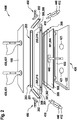
1 einen montierten Solarkollektor mit vier schematisch angedeuteten Montagedornen einer Fügevorrichtung; -
2 Komponenten eines Solarkollektors in Explosionsdarstellung mit schematisch angedeuteten Komponenten einer Fügevorrichtung; -
3 drei Querschnitte durch ein Rahmenteil; -
4 zwei erste Rahmenteile im Querschnitt mit eingeführten Montagedornen; -
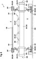
5 zwei erste Rahmenteile im Querschnitt und ein Sammelrohr eines Solarabsorber-Rohrleitungssystems mit eingeführten Montagedornen, sowie transparente Abdeckung, Absorberblech mit Leitrohren und Rückwand; -
6 einen montierten Solarkollektor im Querschnitt entsprechend5 .
-
1 an assembled solar collector with four schematically indicated assembly mandrels of a joining device; -
2nd Components of a solar collector in an exploded view with schematically indicated components of a joining device; -
3rd three cross sections through a frame part; -
4th two first frame parts in cross section with inserted assembly mandrels; -
5 two first frame parts in cross-section and a collector pipe of a solar absorber piping system with inserted assembly mandrels, as well as transparent cover, absorber plate with guide pipes and rear wall; -
6 a mounted solar collector in cross section accordingly5 .
Damit die ersten Rahmenteile
Ein besonderer Vorteil der Erfindung ergibt sich daraus, dass die ersten Rahmenteile
Claims (13)
Priority Applications (2)
| Application Number | Priority Date | Filing Date | Title |
|---|---|---|---|
| DE102018220249.4A DE102018220249A1 (en) | 2018-11-26 | 2018-11-26 | Method and joining device for mounting a solar collector |
| EP19211089.8A EP3657093B1 (en) | 2018-11-26 | 2019-11-25 | Process and joining device for mounting a solar collector |
Applications Claiming Priority (1)
| Application Number | Priority Date | Filing Date | Title |
|---|---|---|---|
| DE102018220249.4A DE102018220249A1 (en) | 2018-11-26 | 2018-11-26 | Method and joining device for mounting a solar collector |
Publications (1)
| Publication Number | Publication Date |
|---|---|
| DE102018220249A1 true DE102018220249A1 (en) | 2020-05-28 |
Family
ID=68655288
Family Applications (1)
| Application Number | Title | Priority Date | Filing Date |
|---|---|---|---|
| DE102018220249.4A Withdrawn DE102018220249A1 (en) | 2018-11-26 | 2018-11-26 | Method and joining device for mounting a solar collector |
Country Status (2)
| Country | Link |
|---|---|
| EP (1) | EP3657093B1 (en) |
| DE (1) | DE102018220249A1 (en) |
Citations (3)
| Publication number | Priority date | Publication date | Assignee | Title |
|---|---|---|---|---|
| US4319844A (en) * | 1978-04-10 | 1982-03-16 | Saint Gobain Industries | Method of adjusting a swiveling solar reflector with multiple reflecting elements supported by prefabricated cambered members |
| DE202005019500U1 (en) * | 2005-12-14 | 2006-03-02 | Schmidt, Patrick | Solar collector with increase in efficiency and ease of assembling has an interior whereby interior of collector is filled with krypton |
| AT506900A1 (en) * | 2008-05-19 | 2009-12-15 | Baumann Holding 1886 Gmbh | PRECAST PANEL SUPPORT STRUCTURE |
Family Cites Families (5)
| Publication number | Priority date | Publication date | Assignee | Title |
|---|---|---|---|---|
| US4252103A (en) * | 1978-07-17 | 1981-02-24 | Advanced Energy Technology | Frame structure for a solar heating panel |
| US20080011289A1 (en) * | 2006-07-14 | 2008-01-17 | National Science And Technology Development Agency | Photovoltaic thermal (PVT) collector |
| IT1390985B1 (en) * | 2008-08-26 | 2011-10-27 | Tvp Solar Sa | SOLAR THERMAL PANEL WITH EMPTY STRUCTURE OF LIGHT |
| US20110146669A1 (en) * | 2009-12-23 | 2011-06-23 | Orion Energy Systems, Inc. | Solar thermal panel |
| DE102014211936A1 (en) * | 2013-06-25 | 2015-01-08 | Thomas Geffert | Solar thermal flat collector |
-
2018
- 2018-11-26 DE DE102018220249.4A patent/DE102018220249A1/en not_active Withdrawn
-
2019
- 2019-11-25 EP EP19211089.8A patent/EP3657093B1/en active Active
Patent Citations (3)
| Publication number | Priority date | Publication date | Assignee | Title |
|---|---|---|---|---|
| US4319844A (en) * | 1978-04-10 | 1982-03-16 | Saint Gobain Industries | Method of adjusting a swiveling solar reflector with multiple reflecting elements supported by prefabricated cambered members |
| DE202005019500U1 (en) * | 2005-12-14 | 2006-03-02 | Schmidt, Patrick | Solar collector with increase in efficiency and ease of assembling has an interior whereby interior of collector is filled with krypton |
| AT506900A1 (en) * | 2008-05-19 | 2009-12-15 | Baumann Holding 1886 Gmbh | PRECAST PANEL SUPPORT STRUCTURE |
Also Published As
| Publication number | Publication date |
|---|---|
| EP3657093A1 (en) | 2020-05-27 |
| EP3657093B1 (en) | 2021-07-14 |
Similar Documents
| Publication | Publication Date | Title |
|---|---|---|
| DE202010006442U1 (en) | Frame for fixing solar modules | |
| EP2765366B1 (en) | Area heater element, method for producing same and tool | |
| DE4137038C1 (en) | Radiator case for front body of motor vehicle - has distance pieces, one elastic, to clamp flat tube heat exchanger between frame and collectors | |
| EP2587182B1 (en) | Sun protection device | |
| DE102008020422B4 (en) | Heating or cooling element with a connection piping | |
| EP3657093B1 (en) | Process and joining device for mounting a solar collector | |
| EP3802981B1 (en) | Radiant ceiling panel with a lighting receptacle, and use of a lighting element with such a radiant ceiling panel | |
| DE102012112837B4 (en) | Vehicle heating and method for producing a vehicle heater | |
| DE102010016177B4 (en) | Heating device for installation in a control cabinet | |
| EP1271063B1 (en) | Heat exchanger, in particular baseboard heater | |
| EP0831282A2 (en) | Baseboard heater for installing heating- or air conditioning systems and eletrical- and/or antenna wires | |
| EP2625471A1 (en) | Cleaning device for photovoltaic and solar thermal systems | |
| DE202018101486U1 (en) | Straight line light | |
| DE29618279U1 (en) | Profile for building frames for photovoltaic generators | |
| EP0677906A1 (en) | Flush mounted box for at least one electrical apparatus | |
| DE102016102790A1 (en) | Ceiling air conditioning unit | |
| CH658308A5 (en) | ENERGY ABSORBERS FOR THE EXPLOITATION OF ENVIRONMENTAL HEAT FROM THE ATMOSPHERA. | |
| EP3001110A1 (en) | Surface tempering system | |
| DE102013208608B3 (en) | Solar thermal flat collector, method for its production, and mounting frame for carrying out the method | |
| DE102006010872B4 (en) | Coating system with coolable aperture | |
| DE102011118871B3 (en) | Solar collector for use on roof, has cladding tube removed from and inserted into tube retainer in pre-assembly position and engaging in retainer in end assembly position, and detent element locking retainer in end assembly position | |
| CH708256A2 (en) | Heat exchangers, solar panel with this heat exchanger and solar collector system. | |
| DE102004023140A1 (en) | Moduldach, especially for halls and residential buildings | |
| DE102012111789A1 (en) | Solar tube collector | |
| DE19847174A1 (en) | Connecting block especially for taking services through wall |
Legal Events
| Date | Code | Title | Description |
|---|---|---|---|
| R163 | Identified publications notified | ||
| R119 | Application deemed withdrawn, or ip right lapsed, due to non-payment of renewal fee |