DE102022128564A1 - Motor device and motor - Google Patents
Motor device and motor Download PDFInfo
- Publication number
- DE102022128564A1 DE102022128564A1 DE102022128564.2A DE102022128564A DE102022128564A1 DE 102022128564 A1 DE102022128564 A1 DE 102022128564A1 DE 102022128564 A DE102022128564 A DE 102022128564A DE 102022128564 A1 DE102022128564 A1 DE 102022128564A1
- Authority
- DE
- Germany
- Prior art keywords
- stator
- rotor
- transport
- unit
- motor device
- Prior art date
- Legal status (The legal status is an assumption and is not a legal conclusion. Google has not performed a legal analysis and makes no representation as to the accuracy of the status listed.)
- Pending
Links
Images




Classifications
-
- H—ELECTRICITY
- H02—GENERATION; CONVERSION OR DISTRIBUTION OF ELECTRIC POWER
- H02K—DYNAMO-ELECTRIC MACHINES
- H02K15/00—Processes or apparatus specially adapted for manufacturing, assembling, maintaining or repairing of dynamo-electric machines
- H02K15/16—Centring rotors within the stators
-
- H—ELECTRICITY
- H02—GENERATION; CONVERSION OR DISTRIBUTION OF ELECTRIC POWER
- H02K—DYNAMO-ELECTRIC MACHINES
- H02K11/00—Structural association of dynamo-electric machines with electric components or with devices for shielding, monitoring or protection
- H02K11/40—Structural association with grounding devices
-
- H—ELECTRICITY
- H02—GENERATION; CONVERSION OR DISTRIBUTION OF ELECTRIC POWER
- H02K—DYNAMO-ELECTRIC MACHINES
- H02K3/00—Details of windings
- H02K3/46—Fastening of windings on the stator or rotor structure
- H02K3/52—Fastening salient pole windings or connections thereto
- H02K3/521—Fastening salient pole windings or connections thereto applicable to stators only
- H02K3/522—Fastening salient pole windings or connections thereto applicable to stators only for generally annular cores with salient poles
-
- H—ELECTRICITY
- H02—GENERATION; CONVERSION OR DISTRIBUTION OF ELECTRIC POWER
- H02K—DYNAMO-ELECTRIC MACHINES
- H02K2213/00—Specific aspects, not otherwise provided for and not covered by codes H02K2201/00 - H02K2211/00
- H02K2213/09—Machines characterised by the presence of elements which are subject to variation, e.g. adjustable bearings, reconfigurable windings, variable pitch ventilators
Landscapes
- Engineering & Computer Science (AREA)
- Power Engineering (AREA)
- Manufacturing & Machinery (AREA)
- Iron Core Of Rotating Electric Machines (AREA)
Abstract
Um eine Motorvorrichtung mit verbesserten Eigenschaften hinsichtlich einer Transportsicherung bereitzustellen, betrifft die vorliegende Erfindung eine Motorvorrichtung (10), insbesondere eine BLDC-Motorvorrichtung, mit einem Rotor (12), welcher in einem Betriebszustand um eine Drehachse (14) drehbar ist, mit einem Stator (16) und mit einer Transportsicherungseinheit (18) zur Sicherung des Rotors (12) relativ zum Stator (16) in zumindest einem Transportzustand.

Description
Stand der TechnikState of the art
Die Erfindung betrifft eine Motorvorrichtung nach Anspruch 1, sowie einen Motor nach Anspruch 15.The invention relates to a motor device according to claim 1, and to a motor according to claim 15.
Aus dem Stand der Technik sind bereits Motorvorrichtungen bekannt, welche in einer Fertigungsstraße hergestellt und direkt in jener Fertigungsstraße in einer separat zu dem Motor hergestellten Baueinheit verbaut und/oder angeordnet werden, und zwar ohne größere Transportstrecken zurücklegen zu müssen.Motor devices are already known from the prior art which are manufactured in a production line and installed and/or arranged directly in that production line in a structural unit manufactured separately from the motor, without having to cover long transport distances.
Die Aufgabe der Erfindung besteht insbesondere darin, eine gattungsgemäße Vorrichtung mit verbesserten Eigenschaften hinsichtlich einer Transportsicherung bereitzustellen. Die Aufgabe wird erfindungsgemäß durch die Merkmale der Ansprüche 1 und 15 gelöst, während vorteilhafte Ausgestaltungen und Weiterbildungen der Erfindung den Unteransprüchen entnommen werden können.The object of the invention is in particular to provide a generic device with improved properties with regard to transport security. The object is achieved according to the invention by the features of claims 1 and 15, while advantageous embodiments and further developments of the invention can be taken from the subclaims.
Vorteile der ErfindungAdvantages of the invention
Die Erfindung betrifft eine Motorvorrichtung, insbesondere eine BLDC-Motorvorrichtung, mit einem Rotor, welcher in einem Betriebszustand um eine Drehachse drehbar ist, mit einem Stator und mit einer Transportsicherungseinheit zur Sicherung des Rotors relativ zum Stator in zumindest einem Transportzustand.The invention relates to a motor device, in particular a BLDC motor device, with a rotor which is rotatable about an axis of rotation in an operating state, with a stator and with a transport locking unit for securing the rotor relative to the stator in at least one transport state.
Durch eine derartige Ausgestaltung kann eine Transportsicherung bereitgestellt werden. Ferner können ein Stator und ein Rotor auf effiziente Art und Weise relativ zueinander in zumindest einem Transportzustand gesichert werden. Damit können Zerstörungen und/oder Beschädigungen des Rotors und/oder Stators bei einem Transport reduziert und/oder verhindert werden. Dadurch kann wiederum eine Sicherheit erhöht werden und eine Effizienz, hinsichtlich einer Produkt- und/oder Kosteneffizienz, gesteigert werden. Such a design can provide a transport lock. Furthermore, a stator and a rotor can be secured in an efficient manner relative to one another in at least one transport state. This can reduce and/or prevent destruction and/or damage to the rotor and/or stator during transport. This in turn can increase safety and efficiency in terms of product and/or cost efficiency.
Darüber hinaus kann ein Bedienkomfort verbessert werden und bevorzugt eine besonders handhabbare und komfortable Transportsicherung bereitgestellt werden.In addition, operating comfort can be improved and, preferably, a particularly easy-to-use and comfortable transport lock can be provided.
Vorzugsweise ist die Motorvorrichtung Teil, und zwar eine Unterbaugruppe eines Motors. Denkbar wäre auch, dass die Motorvorrichtung den gesamten Motor ausbildet. Die Motorvorrichtung kann eine elektronisch kommutierte Motorvorrichtung sein. Insbesondere ist die Motorvorrichtung als BLDC-Motorvorrichtung ausgebildet. Vorteilhaft handelt es sich bei dem Motor um einen elektronisch kommutierten Elektromotor. Elektronisch kommutierte Elektromotoren werden umgangssprachlich auch als „bürstenlose Gleichstrommotoren“ (BLDC-Motoren) bezeichnet, wobei es sich hierbei jedoch um Wechselstrommotoren, insbesondere um Synchronmotoren, handelt, deren Kommutierung mittels elektronischer Halbleiter-Bauteile, beispielsweise MOSFETs und/oder dergleichen, erfolgt, und zwar anstatt über Kohlebürsten, wie es bei Bürsten-Gleichstrommotoren der Fall ist.Preferably, the motor device is part, specifically a subassembly of a motor. It would also be conceivable for the motor device to form the entire motor. The motor device can be an electronically commutated motor device. In particular, the motor device is designed as a BLDC motor device. The motor is advantageously an electronically commutated electric motor. Electronically commutated electric motors are also colloquially referred to as "brushless direct current motors" (BLDC motors), although these are alternating current motors, particularly synchronous motors, whose commutation takes place by means of electronic semiconductor components, for example MOSFETs and/or the like, rather than via carbon brushes, as is the case with brushed direct current motors.
Der Motor ist dazu vorgesehen, elektrische Energie in mechanische Energie, und zwar Bewegungsenergie umzuwandeln. Insbesondere wechselwirkt der Motor in zumindest einem Betriebszustand, vorteilhaft dem bereits genannten Betriebszustand, mit zumindest einer externen Baueinheit, und zwar treibt der Motor die externe Baueinheit an. Die externe Baueinheit kann beispielsweise als Zahnrad oder dergleichen zur Übertragung der mechanischen Energie an zumindest eine weitere Baueinheit ausgebildet sein. Beispielsweise könnte die weitere Baueinheit ein Türgriff sein, welcher mittels des Motors mechanisch öffnen- und/oder verschließbar ist. Die weitere Baueinheit kann jede beliebige, dem Fachmann in Zusammenhang mit der vorliegenden Erfindung als sinnvoll erscheinende Baueinheit sein. Bevorzugt ist der Motor in dem Betriebszustand in einer separat zu dem Motor ausgebildeten Gehäuseeinheit angeordnet. Vorteilhaft ist an und/oder in der Gehäuseeinheit die externe Baueinheit und/oder zumindest die weitere Baueinheit angeordnet. Die externe Baueinheit und/oder zumindest die weitere Baueinheit könnten auch Teil der Gehäuseeinheit sein und eine Unterbaugruppe der Gehäuseeinheit ausbilden.The motor is intended to convert electrical energy into mechanical energy, namely kinetic energy. In particular, the motor interacts in at least one operating state, advantageously the operating state already mentioned, with at least one external structural unit, and the motor drives the external structural unit. The external structural unit can be designed, for example, as a gear or the like for transmitting the mechanical energy to at least one further structural unit. For example, the further structural unit could be a door handle which can be mechanically opened and/or closed by means of the motor. The further structural unit can be any structural unit that appears to be useful to the person skilled in the art in connection with the present invention. In the operating state, the motor is preferably arranged in a housing unit that is designed separately from the motor. The external structural unit and/or at least the further structural unit are advantageously arranged on and/or in the housing unit. The external structural unit and/or at least the further structural unit could also be part of the housing unit and form a subassembly of the housing unit.
Der Motor kann unabhängig von der Gehäuseeinheit hergestellt und/oder produziert werden, beispielsweise von derselben oder unterschiedlichen Firmen. Insbesondere ist der Motor nachträglich, und zwar nach einer jeweiligen separaten Herstellung des Motors und der Gehäuseeinheit, in die Gehäuseeinheit einsetzbar. Vorteilhaft weist die Gehäuseeinheit zumindest einen speziell für den Motor, insbesondere in Abhängigkeit von einer Form, Größe und/oder Ausgestaltung des Motors, vorgesehenen und/oder ausgebildeten Lagerbereich auf, innerhalb welchem der Motor in die Gehäuseeinheit einsetzbar und/oder innerhalb der Gehäuseeinheit positionierbar ist. Bevorzugt ist der Motor in dem Betriebszustand und in zumindest einem montieren Zustand in dem Lagerbereich in der Gehäuseeinheit gelagert und/oder angeordnet und/oder positioniert. Insbesondere ist die Motorvorrichtung in dem montierten Zustand in der Gehäuseeinheit gelagert und/oder angeordnet und/oder positioniert.The motor can be manufactured and/or produced independently of the housing unit, for example by the same or different companies. In particular, the motor can be subsequently inserted into the housing unit, namely after the motor and the housing unit have been manufactured separately. The housing unit advantageously has at least one bearing area which is specifically provided and/or designed for the motor, in particular depending on a shape, size and/or configuration of the motor, within which the motor can be inserted into the housing unit and/or positioned within the housing unit. Preferably, the motor is stored and/or arranged and/or positioned in the bearing area in the housing unit in the operating state and in at least one assembled state. In particular, the motor device is stored and/or arranged and/or positioned in the housing unit in the assembled state.
Vorzugsweise ist der Rotor in dem Betriebszustand und in dem montierten Zustand um die Drehachse drehbar in dem Lagerbereich gelagert und/oder angeordnet. Die Drehachse kann Teil der Motorvorrichtung sein. Besonders bevorzugt ist der Rotor in dem Betriebszustand drehbar innerhalb des Stators gelagert. Der Stator kann einen Rotoraufnahmebereich aufweisen. In dem Betriebszustand kann der Rotor drehbar in dem Rotoraufnahmebereich angeordnet und/oder gelagert sein. Insbesondere umschließt der Stator den Rotor in Umfangsrichtung vollständig. Vorteilhaft ist der Rotor in dem Betriebszustand zur kontaktfreien Rotation relativ zum Stator zumindest abschnittsweise und bevorzugt vollständig in Umfangsrichtung beabstandet zu einer Innenseite, insbesondere einer Innenmantelfläche, des Stators angeordnet.Preferably, the rotor in the operating state and in the assembled state is rotated by the axis is rotatably mounted and/or arranged in the bearing area. The axis of rotation can be part of the motor device. In the operating state, the rotor is particularly preferably rotatably mounted within the stator. The stator can have a rotor receiving area. In the operating state, the rotor can be rotatably arranged and/or mounted in the rotor receiving area. In particular, the stator completely encloses the rotor in the circumferential direction. In the operating state, the rotor is advantageously arranged at a distance from an inner side, in particular an inner surface, of the stator for contact-free rotation relative to the stator, at least in sections and preferably completely in the circumferential direction.
Insbesondere ist der Rotor dazu vorgesehen, in dem Rotoraufnahmebereich des Stators zur Rotation um die Drehachse angetrieben zu werden. Bevorzugt ist der Stator dazu vorgesehen, ein magnetisches Wechselfeld bereitzustellen, um mit zumindest einer magnetischen Komponente des Rotors zu wechselwirken, um damit wiederum den Rotor anzutreiben. Durch Bestromung des Stators und damit einhergehenden Erzeugung von elektromagnetischen Wechselfeldern kann sich der Rotor in dem Betriebszustand innerhalb des Stators drehen.In particular, the rotor is provided to be driven in the rotor receiving area of the stator to rotate about the axis of rotation. The stator is preferably provided to provide an alternating magnetic field to interact with at least one magnetic component of the rotor in order to drive the rotor. By energizing the stator and thereby generating alternating electromagnetic fields, the rotor can rotate within the stator in the operating state.
Der Stator kann einen Statorkern aufweisen. Der Statorkern kann ein magnetisches Rückschlusselement aufweisen. Das Rückschlusselement kann zumindest teilweise, vorteilhaft zumindest zu einem Großteil und besonders bevorzugt vollständig, aus einem Metall und/oder einem Verbundmaterial bestehen. Bevorzugt ist das Rückschlusselement aus einem ferromagnetischen Material zumindest zu einem Großteil oder vollständig ausgebildet. Vorteilhaft besteht der Statorkern, insbesondere das magnetische Rückschlusselement, vollständig aus zumindest einem Metallblech, und zwar aus geblechtem Eisen, insbesondere zumindest einem Elektroblech. Besonders bevorzugt besteht der Statorkern, insbesondere das Rückschlusselement, aus einer Vielzahl von Elektroblechen, insbesondere einem Elektroblechpaket, ferner einem Stapel von Elektroblechen, welche miteinander verbunden, beispielsweise vernietet sind. Insbesondere ist jedes Elektroblech einstückig, bevorzugt einteilig, ausgebildet. Ein einzelnes Blech der Vielzahl von Elektroblechen kann eine Blechstärke von zumindest 0,3 mm, vorteilhaft zumindest 0,35 mm und besonders bevorzugt höchstens 0,50 mm aufweisen. Unter dem Ausdruck „zu einem Großteil“ sollen vorliegend beispielsweise zumindest 55 %, vorteilhaft zumindest 65 %, vorzugsweise zumindest 75 %, besonders bevorzugt zumindest 85 % und besonders vorteilhaft höchstens 95 % eines Flächen- und/oder Volumen- und/oder Massenanteils verstanden werden.The stator can have a stator core. The stator core can have a magnetic return element. The return element can consist at least partially, advantageously at least to a large extent and particularly preferably completely, of a metal and/or a composite material. The return element is preferably made of a ferromagnetic material at least to a large extent or completely. The stator core, in particular the magnetic return element, advantageously consists entirely of at least one metal sheet, namely of laminated iron, in particular at least one electrical sheet. The stator core, in particular the return element, particularly preferably consists of a large number of electrical sheets, in particular an electrical sheet package, and also a stack of electrical sheets, which are connected to one another, for example riveted. In particular, each electrical sheet is formed in one piece, preferably in one piece. An individual sheet of the large number of electrical sheets can have a sheet thickness of at least 0.3 mm, advantageously at least 0.35 mm and particularly preferably at most 0.50 mm. The expression “to a large extent” is to be understood in the present case as meaning, for example, at least 55%, advantageously at least 65%, preferably at least 75%, particularly preferably at least 85% and particularly advantageously at most 95% of an area and/or volume and/or mass proportion.
Insbesondere weist das Rückschlusselement eine Außenmantelfläche auf, welche zumindest abschnittsweise oder vollständig in Umfangsrichtung des Stators eine Außenseite des Statorkerns bildet. Der Statorkern kann zumindest einen Statorzahn aufweisen. Bevorzugt weist der Statorkern mehrere, und zwar zumindest zwei Statorzähne auf, welche an der Innenseite des Stators in Umfangsrichtung angeordnet sind. Vorzugsweise umfasst der Statorkern eine ungerade Anzahl an Statorzähnen, und zwar zumindest drei, vorteilhaft zumindest neun Statorzähne. Insbesondere ist der Statorzahn dazu vorgesehen, zumindest abschnittsweise mit einem Spulendraht bewickelt zu werden sowie den Spulendraht zu tragen und/oder zu halten. Insbesondere erstrecken sich die Statorzähne ausgehend von dem Rückschlusselement radial nach innen. Der Statorkern kann einstückig, vorzugsweise einteilig, ausgebildet sein. Vorteilhaft sind die Statorzähne und das Rückschlusselement zumindest teilweise einstückig, besonders bevorzugt einteilig ausgebildet. Alternativ wäre auch denkbar, dass die Statorzähne und das Rückschlusselement sich hinsichtlich zumindest eines Materials und/oder einer Materialzusammensetzung unterscheiden und insbesondere zumindest teilweise aus verschiedenen Materialien und/oder Materialzusammensetzungen ausgebildet sind. Der Statorzahn kann auf der Innenseite des Stators zumindest einen Polschuh aufweisen. Jeder Statorzahn der Statorzähne des Statorkerns kann zumindest einen Polschuh aufweisen oder ausbilden. Insbesondere begrenzen die Polschuhe zumindest abschnittsweise den Rotoraufnahmebereich. Vorteilhaft ist der Rotor in dem Betriebszustand und in dem montierten Zustand zumindest abschnittsweise und bevorzugt vollständig in Umfangsrichtung beabstandet zu den Polschuhen des Stators angeordnet.In particular, the return element has an outer surface which forms an outer side of the stator core at least partially or completely in the circumferential direction of the stator. The stator core can have at least one stator tooth. The stator core preferably has several, namely at least two stator teeth, which are arranged on the inside of the stator in the circumferential direction. The stator core preferably comprises an odd number of stator teeth, namely at least three, advantageously at least nine stator teeth. In particular, the stator tooth is intended to be wound with a coil wire at least in sections and to carry and/or hold the coil wire. In particular, the stator teeth extend radially inwards from the return element. The stator core can be formed in one piece, preferably in one piece. Advantageously, the stator teeth and the return element are at least partially formed in one piece, particularly preferably in one piece. Alternatively, it would also be conceivable for the stator teeth and the return element to differ with regard to at least one material and/or one material composition and in particular to be formed at least partially from different materials and/or material compositions. The stator tooth can have at least one pole shoe on the inside of the stator. Each stator tooth of the stator teeth of the stator core can have or form at least one pole shoe. In particular, the pole shoes delimit the rotor receiving area at least in sections. Advantageously, the rotor in the operating state and in the assembled state is arranged at a distance from the pole shoes of the stator at least in sections and preferably completely in the circumferential direction.
Der Stator kann eine Nutisolationseinheit mit zumindest einem Nutisolationselement aufweisen, welches an dem Statorkern angeordnet ist. Vorteilhaft weist die Nutisolationseinheit ein erstes Nutisolationselement und zumindest ein zweites Nutisolationselement auf, welche an verschiedenen Seiten, bevorzugt sich gegenüberliegenden Seiten des Statorkerns, bezüglich einer Axialrichtung, insbesondere entlang der Drehachse betrachtet, an dem Statorkern angeordnet sind. Das erste Nutisolationselement und das zweite Nutisolationselement können jeweils zumindest teilweise, vorteilhaft zumindest zu einem Großteil oder vollständig, aus einem Mineral, beispielsweise Keramik, einem Kunststoff, insbesondere einem thermoplastischen Kunststoff, beispielsweise einem Polymer, insbesondere Polyamid, vorzugsweise glasfaserverstärktem Polyamid, und/oder einem Verbundmaterial ausgebildet sein. Vorzugsweise sind das erste Nutisolationselement und das zweite Nutisolationselement jeweils zumindest teilweise einstückig, insbesondere einteilig. Bevorzugt ist zumindest eine der Nutisolationselemente, und zwar das erste Nutisolationselement und/oder das zweite Nutisolationselement vollständig aus einem Kunststoff ausgebildet.The stator can have a slot insulation unit with at least one slot insulation element, which is arranged on the stator core. The slot insulation unit advantageously has a first slot insulation element and at least one second slot insulation element, which are arranged on the stator core on different sides, preferably opposite sides of the stator core, with respect to an axial direction, in particular along the axis of rotation. The first slot insulation element and the second slot insulation element can each be formed at least partially, advantageously at least to a large extent or completely, from a mineral, for example ceramic, a plastic, in particular a thermoplastic plastic, for example a polymer, in particular polyamide, preferably glass fiber reinforced polyamide, and/or a composite material. Preferably, the first slot insulation element and the second slot insulation element are each at least partially in one piece, in particular one-piece. Preferably, at least one of the slot insulation elements, namely the first slot insulation element and/or the second slot insulation element, is made entirely from a plastic.
Unter „einstückig“ soll in diesem Dokument zumindest stoffschlüssig verbunden verstanden werden, beispielsweise durch einen Klebeprozess, einen Anspritzprozess und/oder Schweißprozess und/oder einen anderen, dem Fachmann als sinnvoll erscheinenden Prozess. Ferner soll unter „einteilig“ in einem Stück geformt verstanden werden. Vorzugsweise wird dieses eine Stück aus einem einzelnen Rohling, einer Masse und/oder einem Guss, besonders bevorzugt in einem Spritzgussverfahren, insbesondere einem Ein- und/oder Mehrkomponenten-Spritzgussverfahren, und/oder in einem Stanzverfahren und/der in einem Blechbiegeprozess und/oder in einem Druckprozess, beispielsweise einem 3D-Druckprozesses, und/oder mittels Thermoformen oder vorteilhaft mittels eines Tiefziehprozesses und/oder einem anderen dem Fachmann als sinnvoll erscheinenden Verfahren aus dem einzelnen Rohling hergestellt.In this document, “one-piece” is to be understood as at least materially connected, for example by an adhesive process, an injection molding process and/or welding process and/or another process that appears to be appropriate to the person skilled in the art. Furthermore, “one-piece” is to be understood as formed in one piece. Preferably, this one piece is made from a single blank, a mass and/or a cast, particularly preferably in an injection molding process, in particular a single and/or multi-component injection molding process, and/or in a punching process and/or in a sheet metal bending process and/or in a printing process, for example a 3D printing process, and/or by means of thermoforming or advantageously by means of a deep-drawing process and/or another process that appears to be appropriate to the person skilled in the art from the single blank.
Das erste Nutisolationselement und/oder das zweite Nutisolationselement kann/können dazu vorgesehen sein, die Statorzähne zumindest abschnittsweise zu umgreifen und/oder zu umschließen. Insbesondere bildet/bilden das erste Nutisolationselement und/oder das zweite Nutisolationselement eine elektrische und/oder materialschützende Isolation für und/oder um die Statorzähne. Das erste Nutisolationselement und das zweite Nutisolationselement können gemeinsam zumindest einen Statorzahn der Statorzähne, vorteilhaft alle Statorzähne, zumindest abschnittsweise umgreifen. Bevorzugt sind das erste Nutisolationselement und das zweite Nutisolationselement jeweils an verschiedenen Seiten bezüglich der Axialrichtung betrachtet an dem Statorzahn, insbesondere an allen Statorzähnen, angeordnet. Insbesondere umgreifen das erste Nutisolationselement und das zweite Nutisolationselement zumindest den Statorzahn jeweils zumindest abschnittsweise von unterschiedlichen, bevorzugt sich gegenüberliegenden, Seiten. Das erste Nutisolationselement und das zweite Nutisolationselement können in einem Verhältnis von 20 %/80 %, vorteilhaft von 40 %/60 % und vorzugsweise von 50 %/50 % bezüglich einer Längserstreckung des Statorzahns den Statorzahn jeweils von verschiedenen Seiten umgreifen. Insbesondere erstreckt sich die Längserstreckung des Statorzahns in Axialrichtung, und zwar zumindest im Wesentlichen parallel zu der Drehachse. Unter „im Wesentlichen parallel“ soll hier eine Ausrichtung einer Richtung relativ zu einer Bezugsrichtung, insbesondere in einer Ebene, verstanden werden, wobei die Richtung gegenüber der Bezugsrichtung eine Abweichung kleiner als 8°, vorteilhaft kleiner als 5° und besonders vorteilhaft kleiner als 2° aufweist.The first slot insulation element and/or the second slot insulation element can be provided to encompass and/or enclose the stator teeth at least in sections. In particular, the first slot insulation element and/or the second slot insulation element form an electrical and/or material-protecting insulation for and/or around the stator teeth. The first slot insulation element and the second slot insulation element can together encompass at least one stator tooth of the stator teeth, advantageously all stator teeth, at least in sections. Preferably, the first slot insulation element and the second slot insulation element are each arranged on different sides with respect to the axial direction on the stator tooth, in particular on all stator teeth. In particular, the first slot insulation element and the second slot insulation element each encompass at least the stator tooth at least in sections from different, preferably opposite, sides. The first slot insulation element and the second slot insulation element can each encompass the stator tooth from different sides in a ratio of 20%/80%, advantageously 40%/60% and preferably 50%/50% with respect to a longitudinal extension of the stator tooth. In particular, the longitudinal extension of the stator tooth extends in the axial direction, at least essentially parallel to the axis of rotation. "Essentially parallel" is to be understood here as an alignment of a direction relative to a reference direction, in particular in a plane, wherein the direction has a deviation from the reference direction of less than 8°, advantageously less than 5° and particularly advantageously less than 2°.
Alternativ wäre auch denkbar, dass lediglich das erste Nutisolationselement oder das zweite Nutisolationselement den Statorzahn umgreift. Vorteilhaft kontaktiert der Spulendraht, insbesondere pro Statorzahn, das erste Nutisolationselement und/oder das zweite Nutisolationselement. Besonders bevorzugt ist der Spulendraht kontaktfrei zu dem Statorkern angeordnet. Zumindest eines der Nutisolationselemente, und zwar das erste Nutisolationselement und/oder das zweite Nutisolationselement kann eine Anschlussvorrichtung des Stators aufnehmen und/oder halten. Der Spulendraht kann von dem Statorzahn, insbesondere nach Umwicklung zumindest eines Statorzahns, vorteilhaft nach Umwicklung von zumindest drei Statorzähnen, zu der Anschlussvorrichtung führbar sein, und zwar bevorzugt ohne das Rückschlusselement zu kontaktieren. Die Anschlussvorrichtung kann zumindest ein Anschlusselement, welches beispielsweise als Steckverbinder, insbesondere als Pin, ausgebildet ist, aufweisen. Der Spulendraht ist mit zumindest dem Pin verbindbar. Insbesondere ist das Anschlusselement zu einer Verbindung mit zumindest einer Leiterplatte zum elektrischen Anschluss des Motors vorgesehen.Alternatively, it would also be conceivable for only the first slot insulation element or the second slot insulation element to surround the stator tooth. The coil wire advantageously contacts the first slot insulation element and/or the second slot insulation element, in particular for each stator tooth. The coil wire is particularly preferably arranged without contact with the stator core. At least one of the slot insulation elements, namely the first slot insulation element and/or the second slot insulation element, can accommodate and/or hold a connection device of the stator. The coil wire can be guided from the stator tooth, in particular after wrapping around at least one stator tooth, advantageously after wrapping around at least three stator teeth, to the connection device, preferably without contacting the return element. The connection device can have at least one connection element, which is designed, for example, as a plug connector, in particular as a pin. The coil wire can be connected to at least the pin. In particular, the connection element is intended for connection to at least one circuit board for electrically connecting the motor.
Der Rotor kann einen Grundkörper aufweisen, welcher drehbar an der Drehachse gelagert ist. Ferner kann der Rotor zumindest einen Magneten, bevorzugt zumindest einen Permanentmagneten, aufweisen. Vorteilhaft weist der Rotor mehrere, und zwar zumindest zwei Magnete, insbesondere zumindest drei Permanentmagnete auf, welche in Umfangsrichtung an der Außenseite des Rotors angeordnet sind. Die Magnete können an dem Grundkörper angeordnet sein. Bevorzugt sind die Magnete und der Grundkörper zumindest teilweise einstückig, möglicherweise zumindest teilweise einteilig, ausgebildet.The rotor can have a base body which is rotatably mounted on the axis of rotation. The rotor can also have at least one magnet, preferably at least one permanent magnet. The rotor advantageously has several, namely at least two magnets, in particular at least three permanent magnets, which are arranged in the circumferential direction on the outside of the rotor. The magnets can be arranged on the base body. The magnets and the base body are preferably at least partially integral, possibly at least partially integral.
Zur Vermeidung von zumindest teilweisen Beschädigungen und/oder Zerstörungen des Rotors und/oder des Stators beim Transport und/oder Einsetzen des Motors, beispielsweise durch unkontrollierte und ungewollte Bewegungen des Rotors relativ zum Stator, ist der Rotor relativ zu dem Stator in dem Transportzustand gesichert. Insbesondere in dem Transportzustand ist der Rotor dreh- und/oder bewegungssicher relativ zu dem Stator gelagert und/oder fixiert. Bevorzugt ist in dem Transportzustand eine kontaktfreie Anordnung des Rotors, insbesondere zumindest des Magnets des Rotors, zu den Polschuhen des Stators gewährleistet und/oder bereitgestellt.In order to avoid at least partial damage and/or destruction of the rotor and/or the stator during transport and/or installation of the motor, for example due to uncontrolled and unwanted movements of the rotor relative to the stator, the rotor is secured relative to the stator in the transport state. In particular in the transport state, the rotor is mounted and/or fixed relative to the stator in a rotationally and/or movement-proof manner. Preferably, in the transport state, a contact-free arrangement of the rotor, in particular at least the magnet of the rotor, to the pole shoes of the stator is ensured and/or provided.
Die Transportsicherungseinheit ist dazu vorgesehen, den Rotor relativ zu dem Stator in zumindest dem Transportzustand zu sichern. Die Transportsicherungseinheit kann den Stator und/oder den Rotor in dem Transportzustand zumindest teilweise vor unkontrollierten und/oder ungewollten Bewegungen bewahren und/oder schützen. Die Transportsicherungseinheit kann den Stator und/oder den Rotor zumindest abschnittsweise kontaktieren und/oder an dem Stator und/oder Rotor zumindest teilweise angeordnet sein. Bevorzugt ist die Transportsicherungseinheit zumindest abschnittsweise kontaktbündig an dem Stator und/oder Rotor angeordnet.The transport locking unit is designed to lock the rotor relative to the stator in at least at least in the transport state. The transport securing unit can at least partially protect and/or prevent the stator and/or the rotor from uncontrolled and/or unwanted movements in the transport state. The transport securing unit can contact the stator and/or the rotor at least in sections and/or be arranged at least in part on the stator and/or rotor. Preferably, the transport securing unit is arranged flush with the stator and/or rotor at least in sections.
Um eine besonders effiziente, und zwar stabile Transportsicherung für einen Stator und Rotor bereitzustellen, wird vorgeschlagen, dass die Transportsicherungseinheit zu einer radialen und/oder axialen Sicherung des Rotors relativ zum Stator vorgesehen ist. Die Transportsicherungseinheit kann in dem Transportzustand eine Drehung, und zwar eine Rotation des Rotors um die Drehachse blockieren und/oder verhindern. Alternativ und/oder zusätzlich kann die Transportsicherungseinheit eine Bewegung des Rotors in vertikaler und/oder horizontaler Richtung relativ zu dem Stator verhindern und/oder blockieren. Bevorzugt verhindert die Transportsicherungseinheit ein Verrutschen und/oder Verschieben des Rotors in Axialrichtung, und zwar entlang der Drehachse relativ zum Stator. Die Transportsicherungseinheit kann ferner dazu vorgesehen sein, einen Anschlag des Rotors, insbesondere einen Anschlag zumindest des Magneten des Rotors, an zumindest einem der Statorzähne, insbesondere einem der Polschuhe, des Statorkerns zu verhindern.In order to provide a particularly efficient, namely stable transport lock for a stator and rotor, it is proposed that the transport lock unit is provided for radial and/or axial securing of the rotor relative to the stator. In the transport state, the transport lock unit can block and/or prevent rotation, namely rotation of the rotor about the axis of rotation. Alternatively and/or additionally, the transport lock unit can prevent and/or block movement of the rotor in the vertical and/or horizontal direction relative to the stator. The transport lock unit preferably prevents slipping and/or displacement of the rotor in the axial direction, namely along the axis of rotation relative to the stator. The transport lock unit can also be provided to prevent a stop of the rotor, in particular a stop of at least the magnet of the rotor, on at least one of the stator teeth, in particular one of the pole shoes, of the stator core.
Unter „vorgesehen“ soll hier und im Folgenden speziell programmiert, ausgelegt und/oder ausgestattet verstanden werden. Darunter, dass ein Objekt zu einer bestimmten Funktion vorgesehen ist, soll verstanden werden, dass das Objekt diese bestimmte Funktion in zumindest einem Anwendungs- und/oder Betriebszustand erfüllt und/oder ausführt.Here and in the following, "intended" is understood to mean specifically programmed, designed and/or equipped. The fact that an object is intended for a specific function is understood to mean that the object fulfills and/or executes this specific function in at least one application and/or operating state.
Ferner wird vorgeschlagen, dass die Transportsicherungseinheit zumindest einen Aufnahmebereich zur zumindest abschnittsweisen Aufnahme des Rotors in dem Transportzustand aufweist. Damit kann eine Transportsicherung für einen Rotor optimiert und stabiler gestaltet werden. In dem Transportzustand kann der Rotor zumindest abschnittsweise und vorteilhaft vollständig kontaktbündig in dem Aufnahmebereich der Transportsicherungseinheit angeordnet sein. Bevorzugt nimmt der Aufnahmebereich zumindest den Grundkörper des Rotors auf.It is further proposed that the transport securing unit has at least one receiving area for at least partially receiving the rotor in the transport state. This allows a transport securing device for a rotor to be optimized and made more stable. In the transport state, the rotor can be arranged at least partially and advantageously completely flush in the receiving area of the transport securing unit. The receiving area preferably receives at least the base body of the rotor.
Des Weiteren wird vorgeschlagen, dass der Aufnahmebereich den Rotor in dem Transportzustand zumindest abschnittsweise in Umfangsrichtung umgreift. Dadurch kann eine Bewegungssicherung eines Rotors in zumindest einem Transportzustand verbessert und unkontrollierte und/oder ungewollte Bewegungen, beispielsweise ein Verrutschen des Rotors relativ zu einem Stator gemindert und/oder verhindert werden. Der Aufnahmebereich kann den Rotor in dem Transportzustand zumindest zu 10 %, vorteilhaft zumindest zu 30 % und besonders bevorzugt zumindest zu 50 % in Umfangsrichtung umgreifen. Der Aufnahmebereich kann an eine Größe, Form und/oder Ausgestaltung des Rotors angepasst sein, um insbesondere zumindest abschnittsweise kontaktbündig den Rotor, vorteilhaft den Grundkörper, aufzunehmen. Bevorzugt nimmt der Aufnahmebereich zumindest abschnittsweise in Umfangsrichtung den Grundkörper des Rotors auf.It is further proposed that the receiving area encompasses the rotor in the transport state at least in sections in the circumferential direction. This can improve the movement security of a rotor in at least one transport state and reduce and/or prevent uncontrolled and/or unwanted movements, for example slipping of the rotor relative to a stator. The receiving area can encompass the rotor in the transport state at least 10%, advantageously at least 30% and particularly preferably at least 50% in the circumferential direction. The receiving area can be adapted to a size, shape and/or configuration of the rotor in order to accommodate the rotor, advantageously the base body, in particular at least in sections in a flush contact manner. The receiving area preferably accommodates the base body of the rotor at least in sections in the circumferential direction.
Bevorzugt ist die Transportsicherungseinheit lösbar mit dem Stator und/oder Rotor verbunden. Die Transportsicherungseinheit kann reversibel an dem Stator und/oder Rotor angeordnet werden. Vorteilhaft ist die Transportsicherungseinheit zerstörungsfrei von dem Stator und/oder Rotor entfernbar und bei Bedarf wieder an dem Stator und/oder Rotor anordenbar. Die Transportsicherungseinheit kann nach der Einsetzung und/oder Anordnung des Motors in dem Lagerbereich der Gehäuseeinheit von dem Stator und/oder Rotor entfernbar sein. Es wäre möglicherweise auch denkbar, dass die Transportsicherungseinheit lediglich beim Transport des Stators und Rotors zur Sicherung vorgesehen ist und bereits vor dem Einsetzen des Motors in den Lagerbereich der Gehäuseeinheit von dem Stator und/oder Rotor entfernbar ist. Bevorzugt ist der Motor mit der Transportsicherungseinheit in den Lagerbereich der Gehäuseeinheit einsetzbar und/oder anordenbar. Vorzugsweise wird nach Einsetzung und/oder Anordnung des Motors in dem Lagerbereich der Gehäuseeinheit die Transportsicherungseinheit von dem Stator und/oder dem Rotor entfernt.The transport securing unit is preferably detachably connected to the stator and/or rotor. The transport securing unit can be arranged reversibly on the stator and/or rotor. The transport securing unit can advantageously be removed from the stator and/or rotor without causing any damage and can be arranged back on the stator and/or rotor if required. The transport securing unit can be removed from the stator and/or rotor after the motor has been inserted and/or arranged in the bearing area of the housing unit. It would also be conceivable for the transport securing unit to only be provided for securing the stator and rotor during transport and to be removable from the stator and/or rotor before the motor is inserted into the bearing area of the housing unit. The motor can preferably be inserted and/or arranged in the bearing area of the housing unit with the transport securing unit. The transport securing unit is preferably removed from the stator and/or rotor after the motor has been inserted and/or arranged in the bearing area of the housing unit.
Um eine besonders effiziente und komfortable Transportsicherungseinheit, hinsichtlich einer Handhabung und/oder Lösbarkeit und/oder Entfernung, bereitzustellen, und damit wiederum einen Bedienerkomfort zu steigern, wird vorgeschlagen, dass die Transportsicherungseinheit durch Drehung um die Drehachse relativ zum Stator von einer Verriegelungsposition in eine Entriegelungsposition überführbar ist.In order to provide a particularly efficient and convenient transport locking unit with regard to handling and/or detachability and/or removal, and thus in turn to increase operator comfort, it is proposed that the transport locking unit can be transferred from a locking position to an unlocking position by rotation about the axis of rotation relative to the stator.
Insbesondere in dem Transportzustand ist die Transportsicherungseinheit in der Verriegelungsposition angeordnet. In der Verriegelungsposition kann die Transportsicherungseinheit den Rotor axial und/oder radial relativ zu dem Stator sichern. In der Entriegelungsposition kann die Transportsicherungseinheit von dem Stator und/oder Rotor zumindest teilweise entfernt und/oder gelöst werden. Durch rechtsseitige und/oder linksseitige Drehung um die Drehachse relativ zum Stator kann die Transportsicherungseinheit von Verriegelungsposition in die Entriegelungsposition überführbar sein. Ausgehend von der Entriegelungsposition kann die Transportsicherungseinheit entlang der Drehachse, und zwar in Axialrichtung von dem Stator wegziehbar und/oder wegschiebbar sein.In particular, in the transport state, the transport securing unit is arranged in the locking position. In the locking position, the transport securing unit can secure the rotor axially and/or radially relative to the stator. In the unlocking position, the transport securing unit can be detached from the stator and/or rotor. at least partially removed and/or released. The transport locking unit can be moved from the locking position to the unlocking position by rotating it to the right and/or left about the axis of rotation relative to the stator. Starting from the unlocking position, the transport locking unit can be pulled and/or pushed away from the stator along the axis of rotation, specifically in the axial direction.
Ein Verfahren zur Einsetzung und/oder Anordnung der Motorvorrichtung in der Gehäuseeinheit, zur Entfernung der Transportsicherung sowie zur Freigabe einer Rotation Rotors kann mehrere Verfahrensschritte und möglicherweise mehrere Verfahrensteilschritte aufweisen. Insbesondere ist das genannte Verfahren dazu vorgesehen, den Stator und/oder den Rotor von dem Transportzustand in den Betriebszustand zu überführen und/oder zu überleiten. In einem ersten Verfahrensschritt kann die Motorvorrichtung in der Gehäuseeinheit, und zwar in dem Lagerbereich angeordnet und/oder positioniert werden. In einem zweiten Verfahrensschritt kann die Transportsicherungseinheit von dem Stator und/oder dem Rotor entfernt werden. Bevorzugt erfolgt der zweite Verfahrensschritt entlang eines zeitlichen Verlaufs des Verfahrens nach dem ersten Verfahrensschritt. Insbesondere wird in dem zweiten Verfahrensschritt, und zwar in einem ersten zweiten Verfahrensteilschritt die Transportsicherungseinheit durch Drehung um die Drehachse relativ zum Stator von der Verriegelungsposition in die Entriegelungsposition überführt. In einem zweiten zweiten Verfahrensteilschritt kann die Transportsicherungseinheit entlang der Drehachse, und zwar in Axialrichtung von dem Stator weggezogen und/oder weggeschoben werden. Bevorzugt erfolgt der erste zweite Verfahrensteilschritt entlang des zeitlichen Verlaufs des Verfahrens vor dem zweiten zweiten Verfahrensteilschritt.A method for inserting and/or arranging the motor device in the housing unit, for removing the transport lock and for enabling rotation of the rotor can comprise several method steps and possibly several method sub-steps. In particular, the method mentioned is intended to transfer and/or transfer the stator and/or the rotor from the transport state to the operating state. In a first method step, the motor device can be arranged and/or positioned in the housing unit, specifically in the storage area. In a second method step, the transport lock unit can be removed from the stator and/or the rotor. The second method step preferably takes place along a temporal course of the method after the first method step. In particular, in the second method step, specifically in a first second method sub-step, the transport lock unit is transferred from the locking position to the unlocking position by rotating it about the axis of rotation relative to the stator. In a second second method sub-step, the transport lock unit can be pulled and/or pushed away from the stator along the axis of rotation, specifically in the axial direction. Preferably, the first second method sub-step takes place along the temporal course of the method before the second second method sub-step.
Ferner wird vorgeschlagen, dass die Transportsicherungseinheit nach Entriegelung zumindest im Wesentlichen senkrecht zu der Drehachse von dem Stator und/oder Rotor entfernbar ist. Dadurch kann ein Entfernen und/oder Lösen eine Transportsicherungseinheit komfortabler, und zwar einfacher und/oder schneller gestaltet werden. Die Transportsicherungseinheit kann in vertikaler Richtung von dem Stator und/oder Rotor entfernt werden. Vorteilhaft ist die Transportsicherungseinheit in vertikaler Richtung hochziehbar. Unter „zumindest im Wesentlichen senkrecht“ soll in diesem Zusammenhang unter einem Winkel zwischen 85° und 95°, vorzugsweise zwischen 88° und 92° und besonders vorteilhaft von 90° verstanden werden. Insbesondere wird in einem dritten zweiten Verfahrensteilschritt die Transportsicherungseinheit zumindest im Wesentlichen senkrecht zu der Drehachse von dem Stator und/oder dem Rotor entfernt, und zwar hochgezogen. Bevorzugt erfolgt der dritte zweite Verfahrensteilschritt entlang des zeitlichen Verlaufs des Verfahrens nach dem zweiten zweiten Verfahrensteilschritt.It is further proposed that the transport securing unit can be removed from the stator and/or rotor at least substantially perpendicular to the axis of rotation after unlocking. This makes removing and/or detaching a transport securing unit more convenient, simpler and/or faster. The transport securing unit can be removed from the stator and/or rotor in a vertical direction. The transport securing unit can advantageously be pulled up in a vertical direction. In this context, “at least substantially perpendicular” is to be understood as an angle between 85° and 95°, preferably between 88° and 92° and particularly advantageously 90°. In particular, in a third second method sub-step, the transport securing unit is removed from the stator and/or the rotor at least substantially perpendicular to the axis of rotation, namely pulled up. The third second method sub-step preferably takes place along the temporal course of the method after the second second method sub-step.
Um eine kompakte und gleichzeitig effiziente Transportsicherungseinheit bereitzustellen, kann die Transportsicherungseinheit scheibenartig ausgebildet sein. Die Transportsicherungseinheit kann zumindest teilweise, vorteilhaft zumindest zu einem Großteil oder vollständig, aus einem Mineral, beispielsweise Keramik, einem Kunststoff, beispielsweise einem Polymer, wie Polyethylen und/oder Polypropylen, und/oder einem Verbundmaterial ausgebildet sein. Vorzugsweise ist die Transportsicherungseinheit einstückig, insbesondere einteilig, und zwar bevorzugt vollständig aus einem Kunststoff ausgebildet. Bevorzugt ist die Transportsicherungseinheit als ein Spritzgussteil ausgebildet.In order to provide a compact and at the same time efficient transport securing unit, the transport securing unit can be designed in the shape of a disk. The transport securing unit can be formed at least partially, advantageously at least to a large extent or completely, from a mineral, for example ceramic, a plastic, for example a polymer such as polyethylene and/or polypropylene, and/or a composite material. The transport securing unit is preferably made in one piece, in particular in one piece, and preferably completely from a plastic. The transport securing unit is preferably designed as an injection-molded part.
Wenn die Transportsicherungseinheit einen Führungsbereich aufweist, welcher sich von dem Aufnahmebereich nach außen erstreckt und eine Führung des Rotors entlang des Führungsbereichs nach außen ermöglicht, kann eine besonders schnelle, einfache und unkomplizierte Entriegelung und/oder Entfernung einer Transportsicherungseinheit von einem Rotor bereitgestellt und/oder ermöglicht werden.If the transport locking unit has a guide region which extends outwards from the receiving region and enables the rotor to be guided outwards along the guide region, a particularly quick, simple and uncomplicated unlocking and/or removal of a transport locking unit from a rotor can be provided and/or enabled.
Insbesondere rutscht und/oder gleitet bei Entfernung der Transportsicherungseinheit von dem Stator und/oder dem Rotor, insbesondere zumindest im Wesentlichen senkrecht zur Drehachse, der Rotor aus dem Aufnahmebereich entlang des Führungsbereichs. In dem dritten zweiten Verfahrensteilschritt kann mittels Entfernung der Transportsicherungseinheit von dem Stator und/oder dem Rotor, insbesondere zumindest im Wesentlichen senkrecht zur Drehachse, der Rotor ausgehend von dem Aufnahmebereich entlang des Führungsbereichs geleitet und/oder geführt werden. Vorteilhaft ist der Führungsbereich von zwei zumindest im Wesentlichen parallel zueinander angeordneten Kanten der Transportsicherungseinheit gebildet und/oder definiert. Der Rotor kann bei Entfernung der Transportsicherungseinheit entlang der zwei zumindest im Wesentlichen parallel zueinander angeordneten Kanten der Transportsicherungseinheit entlanggleiten und/oder entlangrutschen. Der Führungsbereich und/oder der Aufnahmebereich könnte/könnten möglicherweise aus einem Grundkörper der Transportsicherungseinheit beispielsweise ausgestanzt und/oder ausgeschnitten sein. Ferner kann/können der Führungsbereich und/oder der Aufnahmebereich bereits ab Werk nach einem Spritzgussverfahren zur Herstellung der Transportsicherungseinheit vorhanden und/oder ausgebildet sein.In particular, when the transport securing unit is removed from the stator and/or the rotor, in particular at least substantially perpendicular to the axis of rotation, the rotor slips and/or slides out of the receiving area along the guide area. In the third, second method sub-step, by removing the transport securing unit from the stator and/or the rotor, in particular at least substantially perpendicular to the axis of rotation, the rotor can be guided and/or guided from the receiving area along the guide area. The guide area is advantageously formed and/or defined by two edges of the transport securing unit that are arranged at least substantially parallel to one another. When the transport securing unit is removed, the rotor can slide and/or glide along the two edges of the transport securing unit that are arranged at least substantially parallel to one another. The guide area and/or the receiving area could possibly be punched out and/or cut out of a base body of the transport securing unit, for example. Furthermore, the guide area and/or the receiving area can already be present and/or formed ex works using an injection molding process for producing the transport securing unit.
Des Weiteren wird vorgeschlagen, dass die Transportsicherungseinheit zumindest abschnittsweise in Umfangsrichtung zumindest ein Sicherungselement aufweist, welches in einer Verriegelungsposition an dem Stator fixiert ist. Hierdurch kann eine Sicherung weiter optimiert und eine besonders stabile Verbindung zwischen einer Transportsicherungseinheit und einem Stator in zumindest einem Transportzustand bereitgestellt werden. Bevorzugt weist die Transportsicherungseinheit mehrere, und zwar zumindest zwei, vorteilhaft zumindest fünf, Sicherungselemente in Umfangsrichtung auf. Das Sicherungselement kann zu einer kraft- und/oder formschlüssigen Verbindung der Transportsicherungseinheit mit dem Stator vorgesehen sein.Furthermore, it is proposed that the transport securing unit at least partially in the circumferential direction, at least one securing element which is fixed to the stator in a locking position. This allows a securing to be further optimized and a particularly stable connection to be provided between a transport securing unit and a stator in at least one transport state. The transport securing unit preferably has several, namely at least two, advantageously at least five, securing elements in the circumferential direction. The securing element can be provided for a force-fitting and/or form-fitting connection of the transport securing unit to the stator.
In einer bevorzugten Ausgestaltung der Erfindung ist das Sicherungselement als Rasthaken ausgebildet. Dadurch kann eine besonders stabile und/oder rutschfeste Transportsicherung, hinsichtlich einer Verriegelung, bereitgestellt werden. Zudem kann eine Entriegelung vereinfacht und/oder komfortabler ausgestaltet werden.In a preferred embodiment of the invention, the securing element is designed as a locking hook. This makes it possible to provide a particularly stable and/or non-slip transport lock with regard to locking. In addition, unlocking can be made simpler and/or more convenient.
Insbesondere ist das Sicherungselement dazu vorgesehen, zumindest eine Rastverbindung mit dem Stator einzugehen. In dem Transportzustand kann das Sicherungselement in eine Öffnung des Stators eingreifen. Bevorzugt bilden der Stator und die Transportsicherungseinheit einen Bajonettverschluss aus bzw. sind in dem Transportzustand mittels eines Bajonettverschlusses miteinander verbunden und/oder fixiert. Vorteilhaft ist die Öffnung Teil des zweiten Nutisolationselements. Das zweite Nutisolationselement kann mehrere, und zwar zumindest zwei Öffnungen aufweisen, welche jeweils zur Wechselwirkung mit korrespondierenden Sicherungselementen der Transportsicherungseinheit vorgesehen sind. Bevorzugt weist das zweite Nutisolationselement zumindest genauso viele Öffnungen auf, wie die Transportsicherungseinheit Sicherungselemente aufweist.In particular, the securing element is provided to form at least one locking connection with the stator. In the transport state, the securing element can engage in an opening in the stator. The stator and the transport securing unit preferably form a bayonet lock or are connected and/or fixed to one another in the transport state by means of a bayonet lock. The opening is advantageously part of the second slot insulation element. The second slot insulation element can have several, namely at least two, openings, each of which is provided for interaction with corresponding securing elements of the transport securing unit. The second slot insulation element preferably has at least as many openings as the transport securing unit has securing elements.
Außerdem wird vorgeschlagen, dass die Transportsicherungseinheit zumindest ein Betätigungselement zur händischen Betätigung und Entfernung der Transportsicherungseinheit vom Stator und/oder Rotor aufweist. Damit kann eine Betätigung und/oder Handhabung einer Transportsicherungseinheit verbessert werden. Zudem kann ein Bedienkomfort weiter optimiert werden.It is also proposed that the transport safety unit has at least one actuating element for manual actuation and removal of the transport safety unit from the stator and/or rotor. This can improve the actuation and/or handling of a transport safety unit. In addition, ease of use can be further optimized.
Das Betätigungselement kann sich in dem Transportzustand, bei Anordnung der Transportsicherungseinheit an dem Stator und/oder Rotor zumindest im Wesentlichen senkrecht zur Drehachse erstrecken. Vorzugsweise erstreckt sich das Betätigungselement radial zu dem Aufnahmebereich. Insbesondere ist das Betätigungselement an einer Außenseite der Transportsicherungseinheit angeordnet. Bevorzugt ist die Transportsicherungseinheit durch Drehung an dem Betätigungselement von der Verriegelungsposition in die Entriegelungsposition überführbar. Ein Bediener kann das Betätigungselement in dem ersten zweiten Verfahrensteilschritt drehen, um damit zumindest das Sicherungselement aus der Verriegelungsposition in die Entriegelungsposition zu überführen. Die Transportsicherungseinheit kann, insbesondere in dem zweiten zweiten Verfahrensteilschritt, mittels des Betätigungselements ausgehend von der Entriegelungsposition entlang der Drehachse, und zwar in Axialrichtung von dem Stator wegziehbar und/oder verschiebbar sein. Bevorzugt schiebt der Bediener in dem zweiten zweiten Verfahrensteilschritt das Betätigungselement entlang der Drehachse, und zwar in Axialrichtung.In the transport state, when the transport securing unit is arranged on the stator and/or rotor, the actuating element can extend at least substantially perpendicular to the axis of rotation. The actuating element preferably extends radially to the receiving area. In particular, the actuating element is arranged on an outer side of the transport securing unit. The transport securing unit can preferably be transferred from the locking position to the unlocking position by rotating the actuating element. An operator can rotate the actuating element in the first second method sub-step in order to thereby transfer at least the securing element from the locking position to the unlocking position. The transport securing unit can, in particular in the second second method sub-step, be pulled and/or displaced away from the stator by means of the actuating element starting from the unlocking position along the axis of rotation, specifically in the axial direction. In the second second method sub-step, the operator preferably pushes the actuating element along the axis of rotation, specifically in the axial direction.
Ferner wird vorgeschlagen, dass die Transportsicherungseinheit in dem Transportzustand bezüglich der Drehachse an einem Ende des Stators angeordnet ist. Hierdurch kann eine kompakte und dennoch stabile sowie sichere Transportsicherung bereitgestellt und/oder ermöglicht werden. Bevorzugt ist das genannte Ende gegenüberliegend zu der Anschlussvorrichtung an dem Stator lokalisiert. Das genannte Ende kann an dem zweiten Nutisolationselement sein. Vorzugsweise ist die Transportsicherungseinheit an dem zweiten Nutisolationselement angeordnet.It is further proposed that the transport securing unit is arranged at one end of the stator in the transport state with respect to the axis of rotation. This makes it possible to provide and/or enable a compact, yet stable and secure transport securing device. Preferably, said end is located opposite the connection device on the stator. Said end can be on the second slot insulation element. Preferably, the transport securing unit is arranged on the second slot insulation element.
Um eine Transportsicherung weiter zu optimieren, und zwar zumindest stabiler zu gestalten sowie eine Rotationssicherung und radiale Sicherung eines Rotors bereitzustellen, wird vorgeschlagen, dass der Rotor in dem Transportzustand zur Rotationssicherung und Bewegungssicherung relativ zum Stator entlang der Drehachse verschoben ist und zumindest abschnittsweise in Umfangsrichtung den Stator kontaktiert.In order to further optimize transport security, and at least to make it more stable and to provide rotation security and radial security of a rotor, it is proposed that the rotor is displaced relative to the stator along the axis of rotation in the transport state for rotation security and movement security and contacts the stator at least in sections in the circumferential direction.
Bevorzugt umfasst die Transportsicherung die Transportsicherungseinheit sowie die Verschiebung des Rotors relativ zu dem Stator. Mittels der Verschiebung des Rotors kann eine Rotationssicherung und/oder vertikale Sicherung des Rotors relativ zu dem Stator ermöglicht werden. Insbesondere ist die Verschiebung des Rotors und Kontaktierung des Rotors mit dem Stator zur axialen und radialen Sicherung des Rotors vorgesehen. Die Nutisolationseinheit kann den Rotor zumindest abschnittsweise in Umfangsrichtung kontaktieren. Vorteilhaft kontaktiert das erste Nutisolationselement den Rotor zumindest abschnittsweise in Umfangsrichtung. Alternativ könnte auch das zweite Nutisolationselement den Rotor zumindest abschnittsweise in Umfangsrichtung kontaktieren. Das erste Nutisolationselement kann den Grundkörper des Rotors und/oder zumindest den Magneten des Rotors kontaktieren. Die Verschiebung des Rotors, insbesondere ausgehend von einer Betriebsposition des Rotors, entlang der Drehachse relativ zum Stator kann zumindest 1 mm, vorteilhaft zumindest 1,5 mm und bevorzugt zumindest 2 mm betragen.The transport lock preferably comprises the transport lock unit and the displacement of the rotor relative to the stator. By means of the displacement of the rotor, rotational security and/or vertical security of the rotor relative to the stator can be enabled. In particular, the displacement of the rotor and contacting of the rotor with the stator is provided for axial and radial securing of the rotor. The slot insulation unit can contact the rotor at least in sections in the circumferential direction. Advantageously, the first slot insulation element contacts the rotor at least in sections in the circumferential direction. Alternatively, the second slot insulation element could also contact the rotor at least in sections in the circumferential direction. The first slot insulation element can contact the base body of the rotor and/or at least the magnet of the rotor. The displacement of the rotor, in particular starting from an operating position of the Rotor, along the axis of rotation relative to the stator can be at least 1 mm, advantageously at least 1.5 mm and preferably at least 2 mm.
Zudem wird vorgeschlagen, dass der Stator und der Rotor in dem Transportzustand zumindest abschnittsweise in Umfangsrichtung zumindest kraftschlüssig aneinander fixiert sind. Damit kann eine besonders stabile axiale und/oder radiale Sicherung eines Rotors relativ zu einem Stator in einem Transportzustand bereitgestellt werden und damit wiederum eine Sicherheit erhöht werden.It is also proposed that the stator and the rotor are fixed to one another in the transport state, at least in sections, in the circumferential direction, at least in a force-fitting manner. This makes it possible to provide a particularly stable axial and/or radial securing of a rotor relative to a stator in a transport state, thus increasing safety.
Der Rotor kann mit dem Stator verkantet sein. Insbesondere ist der Rotor entlang der Drehachse soweit relativ zu dem Stator verschoben, bis zumindest ein Anschlagelement des Stators den Rotor kontaktiert und/oder an dem Rotor anschlägt. Vorteilhaft ist das Anschlagelement als eine Anschlagnase ausgebildet. Das Anschlagelement kann Teil des zweiten Nutisolationselements sein. Bevorzugt ist das Anschlagelement Teil des ersten Nutisolationselements. Vorzugsweise ist das Anschlagelement an zumindest einem der Statorzähne angeordnet. Das Anschlagelement kann den Grundkörper des Rotors und/oder zumindest den Magneten des Rotors kontaktieren.The rotor can be tilted with the stator. In particular, the rotor is displaced along the axis of rotation relative to the stator until at least one stop element of the stator contacts the rotor and/or strikes the rotor. The stop element is advantageously designed as a stop lug. The stop element can be part of the second slot insulation element. Preferably, the stop element is part of the first slot insulation element. Preferably, the stop element is arranged on at least one of the stator teeth. The stop element can contact the base body of the rotor and/or at least the magnet of the rotor.
Um einen Komfort weiter zu optimieren und eine leichte, einfache und/oder schnelle Positionierung und/oder Ausrichtung eines Rotors zu einem Stator zur Inbetriebnahme bereitzustellen, wird vorgeschlagen, dass der Rotor zur Freigabe aus dem Transportzustand entlang der Drehachse relativ zu dem Stator verschiebbar ist.In order to further optimize comfort and to provide easy, simple and/or quick positioning and/or alignment of a rotor to a stator for commissioning, it is proposed that the rotor be displaceable along the axis of rotation relative to the stator for release from the transport state.
Insbesondere wird in einen dritten Verfahrensschritt des genannten Verfahrens der Rotor entlang der Drehachse relativ zu dem Stator verschoben. Der Rotor kann soweit entlang der Drehachse verschiebbar sein, bis das Zahnradelement vollständig in die externe Baueinheit eingreift und/oder der Rotor, insbesondere der Magnet des Rotors, frei von einer Kontaktierung zu dem Stator, insbesondere dem Anschlagelement, ist. Insbesondere ist der Magnet nach Verschiebung des Rotors, und zwar in dem Betriebszustand des Rotors fluchtend, bevorzugt unverschoben, zu dem Rückschlusselement des Stators ausgerichtet, vorzugsweise parallel und unterhalb vom Rückschlusselement angeordnet, und zwar bei einer senkrechten Betrachtung zu dem Rückschlusselement und/oder der Drehachse. Insbesondere ist der Magnet des Rotors in dem Betriebszustand konzentrisch zu dem Rückschlusselement angeordnet. Besonders bevorzugt nach Entfernung der Transportsicherungseinheit und Positionskorrektur des Rotors relativ zu dem Stator ist die Motorvorrichtung, ferner der Motor betriebsbereit.In particular, in a third method step of the method mentioned, the rotor is displaced along the axis of rotation relative to the stator. The rotor can be displaceable along the axis of rotation until the gear element fully engages the external structural unit and/or the rotor, in particular the magnet of the rotor, is free from contact with the stator, in particular the stop element. In particular, after displacement of the rotor, and in fact in the operating state of the rotor, the magnet is aligned, preferably not displaced, with the return element of the stator, preferably parallel and arranged below the return element, in fact when viewed perpendicular to the return element and/or the axis of rotation. In particular, the magnet of the rotor is arranged concentrically to the return element in the operating state. Particularly preferably, after removal of the transport locking unit and correction of the position of the rotor relative to the stator, the motor device, and also the motor, are ready for operation.
Die Motorvorrichtung und/oder der Motor soll/sollen hierbei nicht auf die oben beschriebene Anwendung und Ausführungsform beschränkt sein. Insbesondere kann/können die Motorvorrichtung und/oder der Motor zu einer Erfüllung einer hierin beschriebenen Funktionsweise eine von einer hierin genannten Anzahl von einzelnen Elementen, Bauteilen, Einheiten und Verfahrensschritten abweichende Anzahl aufweisen. Zudem sollen bei den in diesem Dokument angegebenen Wertebereichen auch innerhalb der genannten Grenzen liegende Werte als offenbart und als beliebig einsetzbar gelten.The motor device and/or the motor should not be limited to the application and embodiment described above. In particular, the motor device and/or the motor can have a number of individual elements, components, units and method steps that differs from the number stated herein in order to fulfill a function described herein. In addition, values within the ranges of values stated in this document that lie within the limits stated should also be considered disclosed and can be used as desired.
Zeichnungendrawings
Weitere Vorteile ergeben sich aus der folgenden Zeichnungsbeschreibung. In den Zeichnungen ist ein Ausführungsbeispiel der Erfindung dargestellt. Die Zeichnungen, die Beschreibung und die Ansprüche enthalten zahlreiche Merkmale in Kombination. Der Fachmann wird die Merkmale zweckmäßigerweise auch einzeln betrachten und zu sinnvollen weiteren Kombinationen zusammenfassen.Further advantages emerge from the following description of the drawings. The drawings show an embodiment of the invention. The drawings, the description and the claims contain numerous features in combination. The person skilled in the art will also expediently consider the features individually and combine them into further useful combinations.
Es zeigen:
-
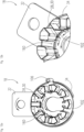
1 einen Motor, welcher eine Motorvorrichtung umfassend einen Stator und einen Rotor aufweist, -
2 eine weitere Ansicht des Motors gemäß1 , -
3 eine Draufsicht auf eine Transportsicherungseinheit der Motorvorrichtung gemäß den1 und2 , -
4 eine Explosionsdarstellung des Motors, -
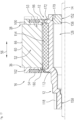
5 eine geschnittene Ansicht des Motors mit einem Schnitt senkrecht zu einer Drehachse der Motorvorrichtung, -
6 eine Detailansicht eines Rückschlusselements des Stators und eines Kontaktelements der Motorvorrichtung zur Kontaktierung des Rückschlusselements mit einem Erdungselement der Motorvorrichtung, -
7 eine geschnittene Einzelansicht des Rotors gelagert an einer Drehachse der Motorvorrichtung und aufweisend einen Grundkörper sowie zumindest einen Magneten, -
8 eine Nahansicht eines Zahnradelements des Rotors in einem ersten als Lagerbereich ausgebildeten Bereich des Rotors zur Lagerung des Rotors an der Drehachse, -
9 eine Einzelansicht der Transportsicherungseinheit, -
10 eine Schnittansicht des Motors gemäß2 mit der Transportsicherungseinheit, wobei sich der Motor in einem Transportzustand befindet, -
11 einen eingesetzten Zustand des Motors in eine separat zu dem Motor ausgebildete Gehäuseeinheit, wobei sich der Motor noch in dem Transportzustand befindet, -
12 eine Überführung der Transportsicherungseinheit von einer Verriegelungsposition in eine Entriegelungsposition relativ zu einem zweiten Nutisolationselement einer Nutisolationseinheit des Stators, an welchem die Transportsicherungseinheit in der Verriegelungsposition fixiert ist, -
13 eine Verschiebung der Transportsicherungseinheit ausgehend von der Entriegelungsposition entlang der Drehachse zur Entfernung von zumindest dem Stator, -
14 ein Herausziehen der Transportsicherungseinheit zur Entfernung von zumindest dem Rotor, -
15 eine Schnittansicht des Motors ohne Transportsicherungseinheit, wobei der Rotor zur Transportsicherung relativ zu dem Stator entlang der Drehachse verschoben ist und mit dem Stator fixiert ist, -
16 eine Verschiebung des Rotors entlang der Drehachse zur Ausrichtung und/oder Positionierung des Rotors relativ zu dem Stator und Loslösung einer Fixierung des Rotors mit dem Stator und -
17 eine Schnittansicht des Motors in einem Betriebszustand, ohne Transportsicherungseinheit und unverschobener Positionierung des Rotors relativ zu dem Stator bzw. Fixierung des Rotors mit dem Stator.
-
1 a motor having a motor device comprising a stator and a rotor, -
2 another view of the engine according to1 , -
3 a plan view of a transport securing unit of the motor device according to the1 and2 , -
4 an exploded view of the engine, -
5 a sectional view of the engine with a section perpendicular to an axis of rotation of the engine device, -
6 a detailed view of a return element of the stator and a contact element of the motor device for contacting the return element with a grounding element of the motor device, -
7 a sectional individual view of the rotor mounted on a rotation axis of the motor device and comprising a base body and at least one magnet, -
8th a close-up view of a gear element of the rotor in a first region of the rotor designed as a bearing region for supporting the rotor on the axis of rotation, -
9 a detailed view of the transport locking unit, -
10 a sectional view of the engine according to2 with the transport safety unit, the engine is in a transport condition, -
11 an inserted state of the motor in a housing unit formed separately from the motor, with the motor still in the transport state, -
12 a transfer of the transport securing unit from a locking position to an unlocking position relative to a second slot insulation element of a slot insulation unit of the stator, to which the transport securing unit is fixed in the locking position, -
13 a displacement of the transport locking unit from the unlocking position along the axis of rotation to remove at least the stator, -
14 pulling out the transport locking unit to remove at least the rotor, -
15 a sectional view of the motor without transport locking unit, wherein the rotor is displaced relative to the stator along the axis of rotation for transport locking and is fixed to the stator, -
16 a displacement of the rotor along the axis of rotation for aligning and/or positioning the rotor relative to the stator and releasing a fixation of the rotor with the stator and -
17 a sectional view of the motor in an operating state, without transport locking unit and unshifted positioning of the rotor relative to the stator or fixation of the rotor with the stator.
Beschreibung des AusführungsbeispielsDescription of the embodiment
Nachfolgend handelt es sich bei den vorliegenden Figuren um schematische und nicht maßstabsgetreue Darstellungen. Wenn nicht anders angegeben, ist von mehrfach vorhandenen Objekten lediglich eins mit einem Bezugszeichen versehen. Zudem sind, um Wiederholungen zu vermeiden, Beschreibungen zu gleichen bzw. identisch ausgebildeten Objekten jeweils analog auf die einzelnen Objekte übertragbar.The following figures are schematic representations and are not to scale. Unless otherwise stated, only one of the objects that exist in multiple copies is provided with a reference symbol. In addition, to avoid repetition, descriptions of the same or identically designed objects can be transferred analogously to the individual objects.
Die Motorvorrichtung 10 weist einen um eine Drehachse 14 drehbar gelagerten Rotor 12 auf. Ferner weist die Motorvorrichtung 10 einen Stator 16 auf. Der Stator 16 ist dazu vorgesehen, den Rotor in einem Rotoraufnahmebereich des Stators 16 aufzunehmen und in Umfangsrichtung zumindest abschnittsweise zu umschließen und/oder zu umgreifen. Gemäß den
Um zumindest teilweise Beschädigungen und/oder Zerstörungen des Rotors 12 und/oder des Stators 16 beim Transport und/oder Einsetzen des Motors 50, beispielsweise durch unkontrollierte und ungewollte Bewegungen des Rotors 12 relativ zum Stator 16 zu vermeiden und/oder zu verhindern, befindet sich der Motor 50 gemäß zumindest den
Die Motorvorrichtung 10 weist ein magnetisches Rückschlusselement 60 auf. Das magnetische Rückschlusselement 60 ist Teil des Stators 16. Das magnetische Rückschlusselement 60 besteht vollständig aus zumindest einem Metallblech, und zwar aus geblechtem Eisen, ferner zumindest einem Elektroblech. Das Rückschlusselement 60 besteht in dieser beispielhaften Ausgestaltung aus einer Vielzahl von Elektroblechen, und zwar einem Elektroblechpaket, wobei die einzelnen Elektrobleche miteinander verbunden, beispielsweise vernietet sind. Eine Außenmantelfläche 66 des Rückschlusselements 60 bildet zumindest abschnittsweise, vorliegend vollständig in Umfangsrichtung des Stators 16 eine Außenseite des Stators 16 (vgl.
Der Stator 16 weist einen Statorkern 52 auf. Der Statorkern 52 weist vorliegend das magnetische Rückschlusselement 60 auf. Ferner bildet die Außenmantelfläche 66 des Rückschlusselements 60 eine Außenseite des Statorkerns 52. Der Statorkern 52 umfasst zumindest einen Statorzahn 53. Vorliegend weist der Statorzahn 52 mehrere, und zwar zumindest zwei Statorzähne 53 auf, welche an einer Innenseite des Stators 16 in Umfangsrichtung angeordnet sind. Die Statorzähne 53 erstrecken sich ausgehend von dem Rückschlusselement 60 radial nach innen. Vorliegend sind die Statorzähne 53 und das Rückschlusselement 60 einteilig ausgebildet. Der Statorkern 52 ist einteilig ausgebildet (vgl.
Die
Zur elektrischen Erdung des Rückschlusselements 60 weist die Motorvorrichtung 10 zumindest ein Erdungselement 62 auf. Das Erdungselement 62 ist vorliegend Teil einer Anschlussvorrichtung 108 der Motorvorrichtung 10. Das Erdungselement 62 ist in dieser beispielhaften Ausgestaltung als Steckverbinder, und zwar als Erdungspin ausgebildet (vgl. beispielsweise
Um eine Kontaktierung des Rückschlusselements 60 mit dem Erdungselement 62 bereitzustellen, weist die Motorvorrichtung 10 ein elastisches Kontaktelement 64 auf, welches das Erdungselement 62 und das Rückschlusselement 60 elektrisch leitend miteinander verbindet (vgl.
Je nach Anordnung und/oder Positionierung des Kontaktelements 64, und zwar je nach Auslenkung und/oder Vorspannung und/oder Verbiegung und/oder Stauchung der Schraubenfeder 70 relativ zu der Außenmantelfläche 66 des Rückschlusselements 60, weist das Kontaktelement 64 mit der Außenmantelfläche 66 des Rückschlusselements 60 zumindest eine Kontaktstelle 98 auf. Um eine besonders stabile und effiziente Kontaktierung zwischen dem Kontaktelement 64 und dem Rückschlusselement 60 zu ermöglichen, weist das Kontaktelement 64 mehr als eine Kontaktstelle 98, beispielsweise zumindest fünf Kontaktstellen 98 mit der Außenmantelfläche 66 des Rückschlusselements 60 auf. Das Kontaktelement 64 ist verformbar, und zwar flexibel biegbar. Ferner ist das Kontaktelement 64 reversibel elastisch verformbar.Depending on the arrangement and/or positioning of the
Mittels des Kontaktelements 64 ist das Erdungselement 62 unmittelbar kontaktfrei zu dem Rückschlusselement 60 angeordnet bzw. ist frei von einem direkten Kontakt zu dem Rückschlusselement 60. Das Kontaktelement 64 ist dazu vorgesehen, eine mittelbare Verbindung und/oder Kontaktierung zwischen dem Erdungselement 62 und dem Rückschlusselement 60 bereitzustellen und/oder zu ermöglichen (vgl.
Ferner kontaktiert eine Mantelfläche 76 der Schraubenfeder 70 das Rückschlusselement 60. Alternativ wäre auch denkbar, dass eine Stirnfläche der Schraubenfeder 70 das Rückschlusselement 60, und zwar die Außenmantelfläche 66 des Rückschlusselements 60 kontaktiert. Vorliegend kontaktiert eine Stirnfläche 72 der Schraubenfeder 70 das Erdungselement 62. Zu Unterscheidungszwecken wird die Stirnfläche 72 im Folgenden als erste Stirnfläche 72 bezeichnet. Die erste Stirnfläche 72 bildet ein erstes Ende der Schraubenfeder 70 aus. Um eine gleichmäßige Kontaktierung der Schraubenfeder 70 mit dem Erdungselement 62 bereitzustellen und/oder zu gewährleisten und/oder eine Steifheit und/der Festigkeit der Schraubenfeder 70 zu optimieren, ist das erste Ende der Schraubenfeder 70 geschlossen, und zwar vorliegend doppelt gewickelt. In dieser beispielhaften Ausgestaltung weist das Rückschlusselement 60 zumindest abschnittsweise eine Beschichtung auf, wobei das Kontaktelement 64 das Rückschlusselement 60 in einem unbeschichteten Abschnitt 68 kontaktiert (vgl.
Zur Halterung zumindest des Kontaktelements 64 relativ zum Rückschlusselement 60 weist die Motorvorrichtung 10 eine Nutisolationseinheit 80 auf (vgl.
Die Nutisolationseinheit 80 weist vorliegend ein erstes Nutisolationselement 100 und ein zweites Nutisolationselement 102 auf (vgl. beispielsweise
Die Nutisolationseinheit 80 weist einen Aufnahmekanal 86 auf, in welchem das Kontaktelement 64 zumindest abschnittsweise angeordnet ist (vgl.
Gemäß der Explosionsdarstellung 4 sowie der Anordnung der Nutisolationseinheit 80 relativ zu dem Kontaktelement 64 und dem Rückschlusselement 60 gemäß
Ferner weist die Nutisolationseinheit 80 eine Halteaufnahme 92 für das Erdungselement 62 auf (vgl. beispielsweise
Ferner sei im Folgenden der Aufbau des Rotors 12 anhand der
Der Rotor 12 weist einen Grundkörper 112 auf. Der Grundkörper 112 ist zumindest zu einem Großteil aus einem Kunststoff ausgebildet. Bei dem Kunststoff handelt es sich um einen gleitoptimierten Kunststoff mit einer hohen Festigkeit, Widerstandsfähigkeit und/oder Wärmebeständigkeit, wie es beispielsweise bei PPA oder PTFE der Fall ist. Der Grundkörper 112 ist einstückig, und zwar einteilig ausgebildet. Vorliegend ist der Grundkörper 112 als ein Spritzgussteil ausgebildet. Ferner ist zumindest ein Magnet 154 des Rotors an den Grundkörper 112 angespritzt. Bei dem Magnet 154 handelt es sich um einen Permanentmagneten. Der Rotor 12 kann noch weitere Magnete 154, beispielsweise zwei oder vier Magnete aufweisen, welche in Umfangsrichtung an einer Außenseite des Rotors angeordnet sind. Der Grundkörper 112 ist zumindest teilweise einstückig oder einteilig ausgebildet.The
In dem ersten Bereich 114 des Rotors 12 ist ein Zahnradelement 118 angeordnet. Das Zahnradelement 118 ist zur Übertragung eines Drehmoments vorgesehen. Vorliegend ist das Zahnradelement 118 in dem montierten Zustand dazu vorgesehen, ein Drehmoment an die externe Baueinheit 186 zu übertragen (vgl.
Der Rotor 12 könnte in dem Zwischenbereich 120 einen zumindest im Wesentlichen konstanten radialen Abstand 136 des Grundkörpers 112 zu der Drehachse 14 aufweisen. Vorliegend weist der Grundkörper 112 jedoch mehrere Bereiche auf, in welchen der radiale Abstand 136 des Grundkörpers 112 von der Drehachse 14 variiert. Gemäß
In
Um bei Herstellung des Rotors 12, und zwar des Grundkörpers 112 einen gleichmäßigen Durchmesser einer Drehachsenlagerung für die Lagerung der Drehachse 14 in dem ersten Bereich 114 zu gewährleisten, weist der Rotor 12 in dem ersten Bereich 114 eine größere Materialstärke auf als in einem unmittelbar zum ersten Bereich 114 benachbarten dritten Bereich 134. In dem ersten Bereich 114 weist der Rotor 12 vorliegend eine Materialstärke von zumindest 2,5 mm auf. Die Materialstärke in dem dritten Bereich 134 beträgt zumindest 2 mm. Der dritte Bereich 134 entspricht genau jenem Abschnitt des Rotors 12, und zwar des Grundkörpers 112, welcher den Unterschied zwischen der Erstreckung des ersten Bereichs 114 und der Erstreckung des Zahnradelements 118 bildet. Der dritte Bereich 134 ist Teil des Zwischenbereichs 120. Der dritte Bereich 134 grenzt unmittelbar an den ersten Bereich 114, und zwar ohne weitere dazwischenliegende Bereiche und/oder Abschnitte des Rotors 12 (vgl.
In dieser beispielhaften Ausgestaltung sind eine erste Gleitkontaktstelle 150 des Rotors 12 mit der Drehachse 14 in dem ersten Bereich 114 und eine zweite Gleitkontaktstelle 152 des Rotors 12 mit der Drehachse 14 in dem zweiten Bereich 116 jeweils aus einem Kunststoff ausgebildet. Der Rotor 12 ist in der ersten Gleitkontaktstelle 150 und in der zweiten Gleitkontaktstelle 152 gleitend an der Drehachse 14 gelagert (vgl.
Der Grundkörper 112 bildet in dem ersten Bereich 114 die erste Gleitkontaktstelle 150 aus. Vorliegend weist der Rotor 12 ein von dem Grundkörper 112 separat ausgebildetes Lagerelement 156 auf, welches die zweite Gleitkontaktstelle 152 aufweist. Bei dem Lagerelement 156 handelt es sich um eine Lagerscheibe. Das Lagerelement 156 ist radial um die Drehachse 14 angeordnet. Das Lagerelement 156 ist zumindest zu einem Großteil aus einem Kunststoff ausgebildet. Vorliegend sind das Lagerelement 156 und der Grundkörper 112 aus dem gleichen Kunststoff hergestellt. Ferner handelt es sich bei dem Kunststoff um den bereits genannten gleitoptimierten Kunststoff.The
Gemäß
Ferner sei im Folgenden im Detail auf die Transportsicherung des Motors 50 eingegangen, welche nach Herstellung des Motors 50 zur Sicherung des Rotors 12 relativ zum Stator 16 beim Transport bis vorliegend zum Einsetzen des Motors 50 in die Gehäuseeinheit 180 sowie Inbetriebnahme des Motors 50 vorgesehen ist. Wie bereits beschrieben, weist die Motorvorrichtung 10 die Transportsicherungseinheit 18 zur Sicherung des Rotors 12 relativ zum Stator 16 in zumindest dem Transportzustand auf. Vorliegend ist die Transportsicherungseinheit 18 zu einer radialen und/oder axialen Sicherung des Rotors 12 relativ zum Stator 16 vorgesehen. In dem Transportzustand ist der Rotor 12 dreh- und/oder bewegungssicher relativ zu dem Stator 16 gelagert und/oder fixiert. Die Transportsicherungseinheit 18 verhindert in dem Transportzustand ein Verrutschen und/oder Verschieben des Rotors 12 in Axialrichtung 56, und zwar entlang der Drehachse 14 relativ zum Stator 16. Ferner ist in dem Transportzustand eine kontaktfreie Anordnung zumindest des Magneten 154 des Rotors 12 zu den Polschuhen 78 des Stators 16 gewährleistet und/oder bereitgestellt. Dadurch kann ein Anschlag des Rotors 12, und zwar ein Anschlag zumindest des Magneten 154 an zumindest einem der Polschuhe 78 verhindert werden. Wie gemäß den
Die Transportsicherungseinheit 18 ist in Einzelansicht in der
Zur Fixierung der Transportsicherungseinheit 18 an dem Stator 16 weist die Transportsicherungseinheit 18 zumindest abschnittsweise in Umfangsrichtung zumindest ein Sicherungselement 28 auf, welches in einer Verriegelungsposition an dem Stator 16 fixiert ist. Gemäß
Ein Verfahren zur Einsetzung und/oder Anordnung der Motorvorrichtung 10 in der Gehäuseeinheit 180, zur Entfernung der Transportsicherung 18 sowie zur Freigabe einer Rotation des Rotors 12 weist mehrere Verfahrensschritte und teilweise mehrere Verfahrensteilschritte auf. Das genannte Verfahren ist dazu vorgesehen, den Stator 16 und den Rotor 12 von dem Transportzustand in den Betriebszustand zu überführen und/oder zu überleiten. In einem ersten Verfahrensschritt wird die Motorvorrichtung 10 in der Gehäuseeinheit 180, und zwar in dem Lagerbereich 182 angeordnet und/oder positioniert werden. Ist der Motor 50 bzw. die Motorvorrichtung 10 in die Gehäuseeinheit 180 eingesetzt, muss zur Inbetriebnahme des Motors 50 zumindest die Transportsicherungseinheit 18 entfernt werden.
In einem zweiten Verfahrensschritt wird die Transportsicherungseinheit 18 von dem Stator 16 und dem Rotor 12 entfernt. Ferner erfolgt der zweite Verfahrensschritt entlang eines zeitlichen Verlaufs des Verfahrens nach dem ersten Verfahrensschritt. In dieser beispielhaften Ausgestaltung ist die Transportsicherungseinheit 18 durch Drehung um die Drehachse 14 relativ zum Stator 16 von einer Verriegelungsposition in eine Entriegelungsposition überführbar. Die
Zur Verbesserung einer Betätigung, und zwar Handhabung der Transportsicherungseinheit 18, weist die Transportsicherungseinheit 18 zumindest ein Betätigungselement 32 zur händischen Betätigung und Entfernung der Transportsicherungseinheit 18 vom Stator 16 und/oder Rotor 12 auf (vgl. beispielsweise
In einem zweiten zweiten Verfahrensteilschritt wird die Transportsicherungseinheit 18 ausgehend von der Entriegelungsposition entlang der Drehachse 14, und zwar in Axialrichtung 56 von dem Stator 16 weggezogen und/oder weggeschoben. Vorliegend erfolgt der erste zweite Verfahrensteilschritt entlang des zeitlichen Verlaufs des Verfahrens vor dem zweiten zweiten Verfahrensteilschritt. Die
Ferner ist die Transportsicherungseinheit 18 nach Entriegelung senkrecht zu der Drehachse 14 von dem Stator 16 und Rotor 12 entfernbar. In einem dritten zweiten Verfahrensteilschritt wird die Transportsicherungseinheit 18 zumindest im Wesentlichen senkrecht zu der Drehachse 14 von dem Stator 16 und dem Rotor 12 entfernt, und zwar hochgezogen (vgl.
Um eine besonders effiziente Transportsicherung bereitzustellen, ist in der vorliegenden Ausführungsform der Rotor 12 in dem Transportzustand zur Bewegungssicherung relativ zum Stator 16 entlang der Drehachse 14 verschoben und kontaktiert zumindest abschnittsweise in Umfangsrichtung den Stator 16. Somit umfasst die Transportsicherung vorliegend die Transportsicherungseinheit 18 sowie die Verschiebung des Rotors 12 relativ zu dem Stator 16. Die
Um den Rotor 12 aus dem fixierten Zustand mit dem Stator 16 zu lösen, ist der Rotor 12 zur Freigabe aus dem Transportzustand entlang der Drehachse 14 relativ zu dem Stator 16 verschiebbar. Die
BezugszeichenReference symbols
- 1010
- MotorvorrichtungMotor device
- 1212
- Rotorrotor
- 1414
- DrehachseRotation axis
- 1616
- Statorstator
- 1818
- TransportsicherungseinheitTransport safety unit
- 2020
- AufnahmebereichRecording area
- 2626
- FührungsbereichManagement area
- 2828
- SicherungselementSecuring element
- 3030
- RasthakenLatching hook
- 3232
- BetätigungselementActuator
- 3434
- Randedge
- 3636
- EndeEnd
- 3838
- EndeEnd
- 5050
- Motorengine
- 5252
- StatorkernStator core
- 5353
- StatorzahnStator tooth
- 5454
- SpulendrahtCoil wire
- 5656
- AxialrichtungAxial direction
- 6060
- RückschlusselementInference element
- 6262
- ErdungselementEarthing element
- 6464
- KontaktelementContact element
- 6666
- AußenmantelflächeOuter surface
- 6868
- AbschnittSection
- 7070
- SchraubenfederCoil spring
- 7272
- StirnflächeFrontal area
- 7474
- StirnflächeFrontal area
- 7676
- MantelflächeShell surface
- 7878
- PolschuhPole shoe
- 8080
- NutisolationseinheitSlot insulation unit
- 8282
- StützflächeSupport surface
- 8484
- NormalrichtungNormal direction
- 8686
- AufnahmekanalRecording channel
- 8888
- HaupterstreckungsrichtungMain extension direction
- 9090
- Winkelangle
- 9292
- HalteaufnahmeHolding fixture
- 9696
- AnschlagnaseStop lug
- 9898
- KontaktstelleContact point
- 100100
- NutisolationselementSlot insulation element
- 102102
- NutisolationselementSlot insulation element
- 104104
- TeilPart
- 106106
- TeilPart
- 108108
- AnschlussvorrichtungConnection device
- 110110
- AnschlusselementeConnection elements
- 112112
- GrundkörperBase body
- 114114
- BereichArea
- 116116
- BereichArea
- 118118
- ZahnradelementGear element
- 120120
- ZwischenbereichIntermediate area
- 126126
- Hohlraumcavity
- 128128
- ErstreckungExtension
- 132132
- ErstreckungExtension
- 134134
- BereichArea
- 136136
- AbstandDistance
- 150150
- GleitkontaktstelleSliding contact point
- 152152
- GleitkontaktstelleSliding contact point
- 154154
- MagneteMagnets
- 156156
- LagerelementBearing element
- 160160
- Öffnungopening
- 170170
- Wulstbead
- 172172
- Vertiefungdeepening
- 180180
- GehäuseeinheitHousing unit
- 182182
- Lagerbereichstorage area
- 186186
- BaueinheitUnit
Claims (15)
Priority Applications (1)
| Application Number | Priority Date | Filing Date | Title |
|---|---|---|---|
| DE102022128564.2A DE102022128564A1 (en) | 2022-10-27 | 2022-10-27 | Motor device and motor |
Applications Claiming Priority (1)
| Application Number | Priority Date | Filing Date | Title |
|---|---|---|---|
| DE102022128564.2A DE102022128564A1 (en) | 2022-10-27 | 2022-10-27 | Motor device and motor |
Publications (1)
| Publication Number | Publication Date |
|---|---|
| DE102022128564A1 true DE102022128564A1 (en) | 2024-05-02 |
Family
ID=90628794
Family Applications (1)
| Application Number | Title | Priority Date | Filing Date |
|---|---|---|---|
| DE102022128564.2A Pending DE102022128564A1 (en) | 2022-10-27 | 2022-10-27 | Motor device and motor |
Country Status (1)
| Country | Link |
|---|---|
| DE (1) | DE102022128564A1 (en) |
Citations (7)
| Publication number | Priority date | Publication date | Assignee | Title |
|---|---|---|---|---|
| DE2260033B2 (en) * | 1972-12-08 | 1977-08-25 | Schorch GmbH, 4050 Mönchengladbach | TRANSPORT SECURITY FOR ELECTRIC MOTORS OF DESIGN B9 |
| DE19755537A1 (en) * | 1997-12-13 | 1999-06-17 | Fhp Motors Gmbh | Transport safety mechanism for assembled and justified motor kit brushless DC motor, e.g for washing machines |
| DE102004058349B3 (en) * | 2004-12-03 | 2006-08-17 | Zf Friedrichshafen Ag | Transport safety device for electrical machine, has transport flange provided with circular base plate, and fastening boreholes provided for receiving fastening screws for fastening flange at rotor carrier of rotor of electric machine |
| DE102010024962A1 (en) * | 2010-06-24 | 2011-12-29 | Minebea Co., Ltd. | Electromotor i.e. drive motor, for fuel pump, has rotor mounted at closed side of motor housing, and transport lock fixed at unsupported side of rotor, where position of rotor is changed without disassembly of motor, lock or rotor |
| US20150097456A1 (en) * | 2012-01-17 | 2015-04-09 | Hitachi Industrial Equipment Systems Co., Ltd. | Cantilevered-Shaft Electric Motor |
| DE102020124151A1 (en) * | 2020-09-16 | 2022-03-17 | Schaeffler Technologies AG & Co. KG | Electrical machine and method for manufacturing and assembling an electrical machine |
| CN216216313U (en) * | 2021-10-22 | 2022-04-05 | Sew-电机(苏州)有限公司 | Electric machine |
-
2022
- 2022-10-27 DE DE102022128564.2A patent/DE102022128564A1/en active Pending
Patent Citations (7)
| Publication number | Priority date | Publication date | Assignee | Title |
|---|---|---|---|---|
| DE2260033B2 (en) * | 1972-12-08 | 1977-08-25 | Schorch GmbH, 4050 Mönchengladbach | TRANSPORT SECURITY FOR ELECTRIC MOTORS OF DESIGN B9 |
| DE19755537A1 (en) * | 1997-12-13 | 1999-06-17 | Fhp Motors Gmbh | Transport safety mechanism for assembled and justified motor kit brushless DC motor, e.g for washing machines |
| DE102004058349B3 (en) * | 2004-12-03 | 2006-08-17 | Zf Friedrichshafen Ag | Transport safety device for electrical machine, has transport flange provided with circular base plate, and fastening boreholes provided for receiving fastening screws for fastening flange at rotor carrier of rotor of electric machine |
| DE102010024962A1 (en) * | 2010-06-24 | 2011-12-29 | Minebea Co., Ltd. | Electromotor i.e. drive motor, for fuel pump, has rotor mounted at closed side of motor housing, and transport lock fixed at unsupported side of rotor, where position of rotor is changed without disassembly of motor, lock or rotor |
| US20150097456A1 (en) * | 2012-01-17 | 2015-04-09 | Hitachi Industrial Equipment Systems Co., Ltd. | Cantilevered-Shaft Electric Motor |
| DE102020124151A1 (en) * | 2020-09-16 | 2022-03-17 | Schaeffler Technologies AG & Co. KG | Electrical machine and method for manufacturing and assembling an electrical machine |
| CN216216313U (en) * | 2021-10-22 | 2022-04-05 | Sew-电机(苏州)有限公司 | Electric machine |
Similar Documents
| Publication | Publication Date | Title |
|---|---|---|
| EP2084806A1 (en) | Electric motor and method for manufacturing an electric motor for a motor vehicle actuator drive | |
| DE102017203736A1 (en) | electric motor | |
| DE10115852A1 (en) | Electric rotating system for DC motor, has iron sheet core with slots, and core insulator fitted with core, in which winding is wound in core slots via core insulator | |
| EP1816727A2 (en) | Electric motor | |
| DE102017216692A1 (en) | Method for electrically contacting a winding of an electrical machine with a printed circuit board | |
| DE102017201438A1 (en) | Laminated core disc with a plurality of laminated core segments and rotor | |
| DE102016214031A1 (en) | Electric motor and a method for producing a stator for an electric motor | |
| EP2605372A2 (en) | Element for retaining permanent magnets on a rotor of an electrical machine | |
| DE102022203959A1 (en) | Rotor for an electric motor | |
| DE102008054330A1 (en) | Claw pole motor i.e. linear stepping motor, has housing part connected with stator part of stator, where stator part comprises coil element that is arranged in axial direction partly outside housing part | |
| WO2009010463A2 (en) | Electrical machine comprising electrically insulated partial windings | |
| DE112023002030T5 (en) | rotor for an electric motor | |
| DE102008040348A1 (en) | Rotor for an electric motor and method for its production | |
| EP2009769A2 (en) | Winding support for an electric motor with individual coils | |
| DE102022128570A1 (en) | Motor device and motor | |
| DE102017216094A1 (en) | Rotor of an electric motor and electric motor | |
| DE102010042697A1 (en) | commutator | |
| EP2619849A1 (en) | Insulation displacement connector for producing an electrical connection and contact-making arrangement with such an insulation displacement connector | |
| DE102022128575A1 (en) | Motor device and motor | |
| DE102010042699A1 (en) | commutator | |
| DE102019119244A1 (en) | Permanently excited inclined electric motor rotor | |
| DE102006017233B4 (en) | Rotor arrangement for an electric machine and claw pole motor | |
| EP2532075B1 (en) | Outer body of an electromecanical energy converter | |
| EP2532077B1 (en) | Mounting aid for a brush-commutated electric motor | |
| DE102010024962A1 (en) | Electromotor i.e. drive motor, for fuel pump, has rotor mounted at closed side of motor housing, and transport lock fixed at unsupported side of rotor, where position of rotor is changed without disassembly of motor, lock or rotor |
Legal Events
| Date | Code | Title | Description |
|---|---|---|---|
| R163 | Identified publications notified |