DE102023128564A1 - reach truck - Google Patents
reach truck Download PDFInfo
- Publication number
- DE102023128564A1 DE102023128564A1 DE102023128564.5A DE102023128564A DE102023128564A1 DE 102023128564 A1 DE102023128564 A1 DE 102023128564A1 DE 102023128564 A DE102023128564 A DE 102023128564A DE 102023128564 A1 DE102023128564 A1 DE 102023128564A1
- Authority
- DE
- Germany
- Prior art keywords
- push
- carriage
- designed
- sensor
- rotation
- Prior art date
- Legal status (The legal status is an assumption and is not a legal conclusion. Google has not performed a legal analysis and makes no representation as to the accuracy of the status listed.)
- Pending
Links
Images

Classifications
-
- B—PERFORMING OPERATIONS; TRANSPORTING
- B66—HOISTING; LIFTING; HAULING
- B66F—HOISTING, LIFTING, HAULING OR PUSHING, NOT OTHERWISE PROVIDED FOR, e.g. DEVICES WHICH APPLY A LIFTING OR PUSHING FORCE DIRECTLY TO THE SURFACE OF A LOAD
- B66F9/00—Devices for lifting or lowering bulky or heavy goods for loading or unloading purposes
- B66F9/06—Devices for lifting or lowering bulky or heavy goods for loading or unloading purposes movable, with their loads, on wheels or the like, e.g. fork-lift trucks
- B66F9/075—Constructional features or details
-
- B—PERFORMING OPERATIONS; TRANSPORTING
- B66—HOISTING; LIFTING; HAULING
- B66F—HOISTING, LIFTING, HAULING OR PUSHING, NOT OTHERWISE PROVIDED FOR, e.g. DEVICES WHICH APPLY A LIFTING OR PUSHING FORCE DIRECTLY TO THE SURFACE OF A LOAD
- B66F9/00—Devices for lifting or lowering bulky or heavy goods for loading or unloading purposes
- B66F9/06—Devices for lifting or lowering bulky or heavy goods for loading or unloading purposes movable, with their loads, on wheels or the like, e.g. fork-lift trucks
- B66F9/075—Constructional features or details
- B66F9/0755—Position control; Position detectors
-
- B—PERFORMING OPERATIONS; TRANSPORTING
- B66—HOISTING; LIFTING; HAULING
- B66F—HOISTING, LIFTING, HAULING OR PUSHING, NOT OTHERWISE PROVIDED FOR, e.g. DEVICES WHICH APPLY A LIFTING OR PUSHING FORCE DIRECTLY TO THE SURFACE OF A LOAD
- B66F9/00—Devices for lifting or lowering bulky or heavy goods for loading or unloading purposes
- B66F9/06—Devices for lifting or lowering bulky or heavy goods for loading or unloading purposes movable, with their loads, on wheels or the like, e.g. fork-lift trucks
- B66F9/075—Constructional features or details
- B66F9/08—Masts; Guides; Chains
- B66F9/10—Masts; Guides; Chains movable in a horizontal direction relative to truck
-
- B—PERFORMING OPERATIONS; TRANSPORTING
- B66—HOISTING; LIFTING; HAULING
- B66F—HOISTING, LIFTING, HAULING OR PUSHING, NOT OTHERWISE PROVIDED FOR, e.g. DEVICES WHICH APPLY A LIFTING OR PUSHING FORCE DIRECTLY TO THE SURFACE OF A LOAD
- B66F9/00—Devices for lifting or lowering bulky or heavy goods for loading or unloading purposes
- B66F9/06—Devices for lifting or lowering bulky or heavy goods for loading or unloading purposes movable, with their loads, on wheels or the like, e.g. fork-lift trucks
- B66F9/075—Constructional features or details
- B66F9/20—Means for actuating or controlling masts, platforms, or forks
- B66F9/24—Electrical devices or systems
Landscapes
- Engineering & Computer Science (AREA)
- Transportation (AREA)
- Structural Engineering (AREA)
- Civil Engineering (AREA)
- Life Sciences & Earth Sciences (AREA)
- Geology (AREA)
- Mechanical Engineering (AREA)
- Chemical & Material Sciences (AREA)
- Combustion & Propulsion (AREA)
- Length Measuring Devices With Unspecified Measuring Means (AREA)
- Forklifts And Lifting Vehicles (AREA)
Abstract
Die Erfindung betrifft einen Schubmaststapler (1) mit einem Fahrzeugkörper (2) und einem an dem Fahrzeugkörper (2) in Fahrzeuglängsrichtung (L) verschiebbar angeordneten Schubschlitten (3), an dem ein Hubmast (7) angeordnet ist, und mit einer Schubwegmesseinrichtung (10), die ausgebildet ist, einen Schubweg und/oder eine Schubposition des Schubschlittens (3) zu ermitteln. Die Schubwegmesseinrichtung (10) weist einen Drehwinkelsensor (11) auf, der an dem Fahrzeugkörper (2) angeordnet ist. Der Drehwinkelsensor (11) ist mittels eines Koppelmechanismus (12) mit dem Schubschlitten (3) verbunden.
Description
Die Erfindung betrifft einen Schubmaststapler mit einem Fahrzeugkörper und einem an dem Fahrzeugkörper in Fahrzeuglängsrichtung verschiebbar angeordneten Schubschlitten, an dem ein Hubmast angeordnet ist, und mit einer Schubwegmesseinrichtung, die ausgebildet ist, einen Schubweg und/oder eine Schubposition des Schubschlittens zu ermitteln.The invention relates to a reach truck with a vehicle body and a push carriage which is arranged on the vehicle body so as to be displaceable in the vehicle longitudinal direction and on which a lifting mast is arranged, and with a push path measuring device which is designed to determine a push path and/or a push position of the push carriage.
Schubmaststapler weisen einen Schubschlitten auf, der an einem Fahrzeugkörper des Schubmaststaplers mittels eines Schubantriebs in horizontaler Fahrzeuglängsrichtung verschoben werden kann. Dabei ist es bekannt, eine Schubwegmesseinrichtung an dem Schubmaststapler vorzusehen, mit der der Schubweg und/oder die Schubposition des Schubschlittens ermittelt werden kann.Reach trucks have a reach carriage that can be moved horizontally along the vehicle's longitudinal direction by means of a push drive. It is known to provide a push travel measuring device on the reach truck, with which the push travel and/or push position of the reach carriage can be determined.
Bei Schubmaststaplern des Standes der Technik ist es bekannt, als Schubwegmesseinrichtung zwei induktive Sensoren vorzusehen, die mit einer Steuereinrichtung verbunden sind und mit einem Kamm zusammenwirken. Die beiden Sensoren sind hierbei an dem Schubschlitten befestigt und der Kamm am Fahrzeugkörper des Schubmaststaplers. Wird der Schubschlitten in Fahrzeuglängsrichtung bewegt, detektieren die induktiven Sensoren die relative Bewegung zu dem Kamm. Die Sensoren senden ein Sinus/Cosinus-Signal an die Steuereinrichtung, die dieses Signal in einen Schubweg und/oder in eine Schubposition des Schubschlittens umgerechnet. Bei bekannten Schubmaststaplern sind die induktiven Sensoren aufgrund der Bauraumgegebenheiten an dem Schubschlitten angeordnet. Dies führt zu Nachteilen, da eine Kabelverbindung, mit der die am Schubschlitten angeordneten Sensoren mit der im Fahrzeugkörper angeordneten Steuereinrichtung verbunden sind, jede Schubbewegung des Schubschlittens mit ausführt, wodurch eine erhöhte Kabelbruchgefahr besteht. Zudem sind lange Kabel und viele Stecker erforderlich. Weiterhin ist nachteilig, dass die Positionsänderung des Schubschlittens nur inkrementell ermittelt wird. Weiterhin ist nachteilig, dass Fehler in der Detektion nicht ermittelt werden können sowie Positionsänderungen des Schubschlittens bei ausgeschalteter Steuereinrichtung nicht erkannt werden können. Zudem können Fremdkörper in der Messstrecke, beispielsweise Metallpackband oder Metallklammern, zu Fehldetektionen führen. Darüber hinaus können mechanische Toleranzen in der gesamten Messstrecke zu Fehldetektionen führen.In prior art reach trucks, it is known to provide two inductive sensors as a push-distance measuring device. These sensors are connected to a control device and interact with a comb. The two sensors are attached to the push carriage, and the comb is attached to the vehicle body of the reach truck. When the push carriage is moved in the longitudinal direction of the vehicle, the inductive sensors detect the relative movement to the comb. The sensors send a sine/cosine signal to the control device, which converts this signal into a push distance and/or a push position of the push carriage. In known reach trucks, the inductive sensors are mounted on the push carriage due to the space constraints. This leads to disadvantages, since a cable connection connecting the sensors mounted on the push carriage to the control device located in the vehicle body carries out every push movement of the push carriage, which increases the risk of cable breakage. In addition, long cables and numerous connectors are required. Another disadvantage is that the change in position of the push carriage is only determined incrementally. Another disadvantage is that detection errors cannot be detected, and position changes of the slider cannot be detected when the control system is switched off. Furthermore, foreign objects in the measuring section, such as metal packing tape or metal staples, can lead to false detections. Furthermore, mechanical tolerances throughout the measuring section can lead to false detections.
Der vorliegenden Erfindung liegt die Aufgabe zugrunde, einen Schubmaststapler der eingangs genannten Gattung zu Verfügung zu stellen, der hinsichtlich der genannten Nachteile verbessert ist.The present invention is based on the object of providing a reach truck of the type mentioned at the outset which is improved with regard to the disadvantages mentioned.
Diese Aufgabe wird erfindungsgemäß dadurch gelöst, dass die Schubwegmesseinrichtung einen Drehwinkelsensor aufweist, der an dem Fahrzeugkörper angeordnet ist, wobei der Drehwinkelsensor mittels eines Koppelmechanismus mit dem Schubschlitten verbunden ist.This object is achieved according to the invention in that the thrust travel measuring device has a rotation angle sensor which is arranged on the vehicle body, wherein the rotation angle sensor is connected to the thrust carriage by means of a coupling mechanism.
Erfindungsgemäß wird somit als Sensor der Schubwegmesseinrichtung, mit dem der Schubweg und/oder die Schubposition des am Fahrzeugkörper in Fahrzeuglängsrichtung verschiebbar angeordneten Schubschlitten ermittelt wird, ein an dem Fahrzeugkörper angeordneter Drehwinkelsensor verwendet, der mittels eines Koppelmechanismus mit dem Schubschlitten verbunden ist. Die Längenänderung des Schubschlittens beim Verschieben des Schubschlittens am Fahrzeugkörper wird mit einer von dem Koppelmechanismus gebildeten kinematischen Anbindung in eine Drehbewegung an dem Drehwinkelsensor gewandelt, der einen entsprechenden Drehwinkel bzw. eine Winkeländerung misst, aus der der Schubweg und/oder die Schubposition des Schubschlittens ermittelt wird.According to the invention, a rotation angle sensor arranged on the vehicle body and connected to the push carriage by means of a coupling mechanism is used as the sensor of the push carriage travel measuring device, with which the push carriage travel and/or the push position of the push carriage arranged on the vehicle body so as to be displaceable in the vehicle's longitudinal direction is determined. The change in length of the push carriage when the push carriage is displaced on the vehicle body is converted into a rotational movement at the rotation angle sensor by a kinematic connection formed by the coupling mechanism. The sensor measures a corresponding rotation angle or angular change, from which the push carriage travel and/or the push position is determined.
Gemäß einer vorteilhaften Ausführungsform der Erfindung weist der Koppelmechanismus einen mit dem Drehwinkelsensor drehfest verbundenen Stab aufweist, der mittels eines Verbindungselements mit dem Schubschlitten verbunden ist. Der Stab ist insbesondere mit einem drehbaren Sensorelement des Drehwinkelsensors drehfest verbunden. Mit einem derartigen aus einem Stab und einem Verbindungselement gebildeten Koppelmechanismus kann auf einfache Weise die Längenänderung des Schubschlittens beim Verschieben des Schubschlittens am Fahrzeugkörper in eine Drehbewegung an dem Drehwinkelsensor gewandelt werden.According to an advantageous embodiment of the invention, the coupling mechanism comprises a rod that is rotationally fixedly connected to the angle of rotation sensor and is connected to the sliding carriage by means of a connecting element. The rod is, in particular, rotationally fixedly connected to a rotatable sensor element of the angle of rotation sensor. With such a coupling mechanism formed from a rod and a connecting element, the change in length of the sliding carriage when the sliding carriage is displaced on the vehicle body can be easily converted into a rotational movement at the angle of rotation sensor.
Gemäß einer vorteilhaften Ausführungsform der Erfindung ist das Verbindungselement als Verbindungstab ausgebildet, der an einem ersten Ende mit dem Stab gelenkig verbunden ist und an einem zweiten Ende mit dem Schubschlitten gelenkig verbunden ist. Mit einem derartigen gelenkig mit dem Stab und gelenkig mit dem Schubschlitten verbundenen Verbindungstab kann einfacher Weise der Stab mit dem Schubschlitten gekoppelt werden.According to an advantageous embodiment of the invention, the connecting element is designed as a connecting rod that is pivotally connected to the rod at a first end and pivotally connected to the push carriage at a second end. With such a connecting rod pivotally connected to the rod and pivotally connected to the push carriage, the rod can be easily coupled to the push carriage.
Gemäß einer vorteilhaften Ausführungsform der Erfindung ist das Verbindungselement als Seil ausgebildet, das an einem ersten Ende mit dem Stab verbunden ist und an einem zweiten Ende mit dem Schubschlitten verbunden ist. Mit einem derartigen mit dem Stab und mit dem Schubschlitten verbundenen Seil kann in besonders einfacher Weise der Stab mit dem Schubschlitten gekoppelt werden.According to an advantageous embodiment of the invention, the connecting element is designed as a cable that is connected to the rod at a first end and to the push carriage at a second end. With such a cable connected to the rod and the push carriage, the rod can be coupled to the push carriage in a particularly simple manner.
Gemäß einer vorteilhaften Ausführungsform der Erfindung steht der Drehwinkelsensor mit einer Steuereinrichtung, insbesondere einer elektronischen Steuereinrichtung, in Wirkverbindung, wobei die Steuereinrichtung ausgebildet ist, anhand des mit dem Drehwinkelsensor gemessenen Drehwinkels den Schubweg und/oder die Schubposition des Schubschlittens zu bestimmen. In einer Steuereinrichtung kann auf einfache Weise aus dem mit dem Drehwinkelsensor gemessenen Drehwinkel der Schubweg und/oder die Schubposition des Schubschlittens bestimmt werden. Bevorzugt sind der Steuereinrichtung die Kinematik des Koppelmechanismus bekannt, so dass auf diese Weise die Steuerung den mit dem Drehwinkelsensor gemessenen Winkel in eine Längenänderung umrechnen kann und den Schubweg und/oder die Schubposition des Schubschlittens bestimmen kann.According to an advantageous embodiment of the invention, the angle of rotation sensor is provided with a control device, in particular an electronic ical control device, in operative connection, wherein the control device is designed to determine the pushing path and/or the pushing position of the pushing carriage based on the rotation angle measured with the rotation angle sensor. In a control device, the pushing path and/or the pushing position of the pushing carriage can be determined in a simple manner from the rotation angle measured with the rotation angle sensor. The kinematics of the coupling mechanism are preferably known to the control device, so that in this way the control can convert the angle measured with the rotation angle sensor into a change in length and determine the pushing path and/or the pushing position of the pushing carriage.
Gemäß einer vorteilhaften Ausführungsform der Erfindung steht der Koppelmechanismus mit einer Federeinrichtung in Wirkverbindung. Mit einer Federeinrichtung kann insbesondere bei der Ausführung des Verbindungselements als Seil das Seil dauerhaft unter Spannung gehalten werden, um bei einer Schubbewegung des Schubschlittens eine Betätigung des Drehwinkelsensors sicherzustellen.According to an advantageous embodiment of the invention, the coupling mechanism is operatively connected to a spring device. A spring device can be used, particularly when the connecting element is designed as a cable, to keep the cable permanently under tension to ensure actuation of the rotation angle sensor during a pushing movement of the sliding carriage.
Gemäß einer vorteilhaften Ausführungsform der Erfindung ist die Federeinrichtung ausgebildet ist, den Drehwinkelsensor in einen Fehlerwinkel zu betätigen. Der Fehlerwinkel liegt bevorzugt außerhalb des Messbereichs des Drehwinkelsensors, in dem der Drehwinkelsensor bei der Schubbewegung des Schubschlittens betätigt wird. Hierdurch wird auf einfache Weise ermöglicht, dass der Drehwinkelsensor bei einem Defekt der Koppeleinrichtung, beispielweise einem Bruch oder Riss des Stabes und/oder des Verbindungselements, von der Federeinrichtung in den Fehlerwinkel betätigt wird.According to an advantageous embodiment of the invention, the spring device is designed to actuate the angle of rotation sensor to an error angle. The error angle preferably lies outside the measuring range of the angle of rotation sensor, within which the angle of rotation sensor is actuated during the pushing movement of the sliding carriage. This makes it easy for the angle of rotation sensor to be actuated to the error angle by the spring device in the event of a defect in the coupling device, for example, a break or crack in the rod and/or the connecting element.
Gemäß einer vorteilhaften Ausführungsform der Erfindung ist die Steuereinrichtung ausgebildet, bei gemessenem Fehlerwinkel eine Fehlermeldung auszugeben. Hierdurch kann auf einfache Weise bei einem Defekt der Koppeleinrichtung eine entsprechende Fehlermeldung erzeugt werden.According to an advantageous embodiment of the invention, the control device is configured to output an error message when an error angle is measured. This allows a corresponding error message to be generated easily in the event of a defect in the coupling device.
Gemäß einer vorteilhaften Ausführungsform der Erfindung ist die Federeinrichtung als Torsionsfeder ausgebildet, die koaxial zu einer Drehachse des Drehwinkelsensors angeordnet ist. Mit einer derartigen Torsionsfeder kann der Koppelmechanismus in einfacher Weise betätigt werden.According to an advantageous embodiment of the invention, the spring device is designed as a torsion spring arranged coaxially with a rotational axis of the rotation angle sensor. With such a torsion spring, the coupling mechanism can be easily actuated.
Gemäß einer vorteilhaften Ausführungsform der Erfindung ist der Drehwinkelsensor als magnetoresitiver Sensor ausgebildet. Mit einem derartigen Sensor kann bei geringem Bauaufwand und mit hoher Zuverlässigkeit ein Drehwinkel erfasst und gemessen werden.According to an advantageous embodiment of the invention, the angle of rotation sensor is designed as a magnetoresistive sensor. Such a sensor can detect and measure a rotation angle with minimal construction effort and high reliability.
Gemäß einer vorteilhaften Ausführungsform der Erfindung ist der Drehwinkelgeber als optischer Sensor ausgebildet. Mit einem optischen Sensor kann bei geringem Bauaufwand und mit hoher Zuverlässigkeit ein Drehwinkel erfasst und gemessen werden.According to an advantageous embodiment of the invention, the rotary encoder is designed as an optical sensor. With an optical sensor, a rotation angle can be detected and measured with minimal construction effort and high reliability.
Gemäß einer vorteilhaften Ausführungsform der Erfindung ist der Drehwinkelgeber als Hall-Sensor ausgebildet. Mit einem Hall-Sensor kann bei geringem Bauaufwand und mit hoher Zuverlässigkeit ein Drehwinkel erfasst und gemessen werden.According to an advantageous embodiment of the invention, the rotary encoder is designed as a Hall sensor. A Hall sensor allows a rotation angle to be detected and measured with minimal construction effort and high reliability.
Gemäß einer vorteilhaften Ausführungsform der Erfindung ist der Drehwinkelgeber als Potentiometer ausgebildet. Mit einem Potentiometer kann bei geringem Bauaufwand und mit hoher Zuverlässigkeit ein Drehwinkel erfasst und gemessen werden.According to an advantageous embodiment of the invention, the rotary encoder is designed as a potentiometer. A potentiometer allows the detection and measurement of a rotation angle with minimal construction effort and high reliability.
Die Erfindung weist eine Reihe von Vorteilen auf.The invention has a number of advantages.
Gemäß der Erfindung ist der Drehwinkelsensor am Fahrzeugkörper angeordnet, wodurch eine Kabelverbindung des Drehwinkelsensors nicht über den ein bewegtes Teil darstellenden Schubschlitten geführt werden muss. Dadurch können Zwischenstecker und Kabellänge eingespart werden. Zusätzlich wird die Gefahr eines Kabelbruchs aufgrund von dauerhaft bewegte elektrische Leitungen vermieden.According to the invention, the angle of rotation sensor is mounted on the vehicle body, eliminating the need to route the cable connection of the angle of rotation sensor over the sliding carriage, which is a moving part. This saves on intermediate connectors and cable length. Furthermore, the risk of cable breakage due to constantly moving electrical wires is avoided.
Mit dem Drehwinkelsensor ist weiterhin eine Absolutwertmessung des Schubwegs und/oder der Schubposition des Schubschlittens möglich, da ein gemessener Drehwinkel immer einer Schubposition des Schubschlittens entspricht.The angle of rotation sensor also enables absolute value measurement of the push travel and/or the push position of the push carriage, since a measured angle of rotation always corresponds to a push position of the push carriage.
Weiterhin ist der Drehwinkelsensor störungsunempfindlich und Fremdkörper, beispielsweise Metalle, führen nicht zu Fehldetektionen.Furthermore, the angle of rotation sensor is insensitive to interference and foreign bodies, such as metals, do not lead to false detections.
In Verbindung mit der Federeinrichtung können Fehler bzw. ein Defekt des Koppelmechanismus in einfacher Weise erkannt werden.In conjunction with the spring device, errors or defects in the coupling mechanism can be easily detected.
Darüber hinaus weist ein Drehwinkelsensor geringe Herstellkosten auf, so dass mit geringem Kostenaufwand eine Absolutwertmesssystem zur Verfügung gestellt werden kann, mit dem der Schubwegs und/oder die Schubposition des Schubschlittens ermittelt werden kann.In addition, a rotary angle sensor has low manufacturing costs, so that an absolute value measuring system can be provided at low cost with which the push travel and/or the push position of the push carriage can be determined.
Weitere Vorteile und Einzelheiten der Erfindung werden anhand der in den schematischen Figuren dargestellten Ausführungsbeispielen näher erläutert. Hierbei zeigt
-
1 einen erfindungsgemäßen Schubmaststapler in einer Seitenansicht, -
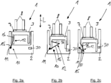
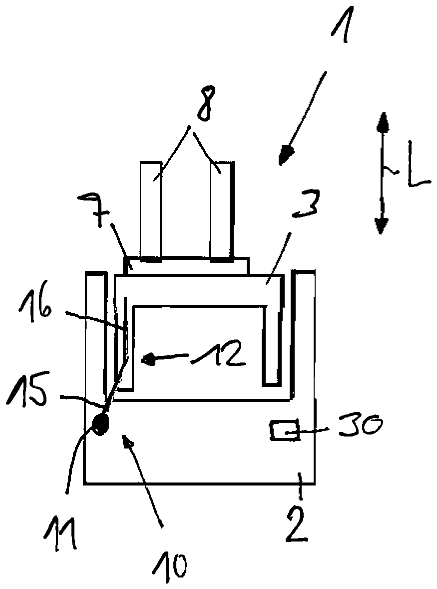
2a bis 2c schematische Draufsichten eines erfindungsgemäßen Schubmaststaplers mit dem Schubschlitten in unterschiedlichen Schubpositionen, -
3 einen Drehwinkelsensor mit einer ersten Ausführungsform des Koppelmechanismus und -
4 einen Drehwinkelsensor mit einer zweiten Ausführungsform des Koppelmechanismus.
-
1 a reach truck according to the invention in a side view, -
2a to 2c schematic plan views of a reach truck according to the invention with the push carriage in different push positions, -
3 a rotation angle sensor with a first embodiment of the coupling mechanism and -
4 a rotation angle sensor with a second embodiment of the coupling mechanism.
In der
Der Schubmaststapler 1 weist einen Fahrzeugkörper 2 auf, an dem in horizontaler Fahrzeuglängsrichtung L ein Schubschlitten 3 mittels eines nicht näher dargestellten Schubantriebs verschiebbar angeordnet ist.The
An dem Fahrzeugkörper 2 ist ein Fahrerstand 5 angeordnet. Ebenfalls an dem Fahrzeugkörper 2 angeordnet ist ein Batterieblock 6, der sämtliche Antriebe des Schubmaststaplers 1 mit elektrischer Energie versorgt.A driver's
An dem Schubschlitten 3 ist ein Hubmast 7 angeordnet, an dem ein Lastaufnahmemittel 8, beispielsweise eine zwei Gabelzinken aufweisende Lastgabel, anhebbar und absenkbar angeordnet ist.A lifting mast 7 is arranged on the
In der
Der Schubmaststapler 1 weist eine in den
In der
Die Schubwegmesseinrichtung 10 weist - wie in den in den
Der Koppelmechanismus 12 weist einen mit dem Drehwinkelsensor 11 drehfest verbundenen Stab 15 auf, der mittels eines Verbindungselements 16 mit dem Schubschlitten 3 verbunden ist.The
Der Stab 15 ist bevorzugt mit einem drehbaren Sensorelement des Drehwinkelsensors 11 drehfest verbunden. Das drehbare Sensorelement ist bevorzugt um eine vertikale Drehachse D drehbar angeordnet. Der Stab 15 ist radial am Drehwinkelsensor 11 angeordnet.The
In der
In der
Die von dem Koppelmechanismus 12 gebildete kinematische Anbindung des Drehwinkelsensors 11 mit dem Schubschlitten 3 besteht somit aus dem Stab 15, der an dem Drehwinkelsensor 11 drehfest verbunden ist und den Drehwinkelsensor 11 betätigt. An der anderen Seite des Stabs 15 ist das mit dem Schubschlitten 3 verbundenen Verbindungselement 16 angelenkt.The kinematic connection of the angle of rotation sensor 11 to the sliding
Gemäß der
In dem Ausführungsbeispiel der
Im normalen Betrieb des Schubmaststaplers 1 wird der Drehwinkelsensor 11 mit einem Drehwinkel innerhalb eines Messbereiches MB betrieben.During normal operation of the
Die Federeinrichtung 25 ist ausgebildet, den Drehwinkelsensor in einen Fehlerwinkel FW zu betätigen. Der Fehlerwinkel FW liegt außerhalb des Drehwinkelbereichs des Messbereichs MB des Drehwinkelsensors 11.The spring device 25 is designed to actuate the angle of rotation sensor to an error angle FW. The error angle FW lies outside the angle of rotation range of the measuring range MB of the angle of rotation sensor 11.
Der Drehwinkelsensor 11 steht mit einer Steuereinrichtung 30, beispielsweise einer elektronischen Steuereinrichtung, in Wirkverbindung. Die Steuereinrichtung 30 ist ausgebildet, anhand des mit dem Drehwinkelsensor 11 gemessenen Drehwinkels den Schubweg und/oder die Schubposition des Schubschlittens 3 zu bestimmen.The angle of rotation sensor 11 is operatively connected to a
Weiterhin ist die Steuereinrichtung 30 ausgebildet, bei gemessenem Fehlerwinkel FW eine Fehlermeldung auszugeben.Furthermore, the
Die Erfindung ist nicht auf die in den Figuren dargestellten Ausführungsbeispiele beschränkt. Die Federeinrichtung 25 der
In den
Die Erfindung arbeitet wie folgt:
- Wird mittels des Schubantriebs der Schubschlitten 3 in Fahrzeuglängsrichtung L verschoben, wird die Längenänderung des Schubschlittens 3 beim Verschieben des Schubschlittens 3
am Fahrzeugkörper 2 mit dervon dem Koppelmechanismus 12 gebildeten kinematischen Anbindung in eine Drehbewegung an dem Drehwinkelsensor 11 gewandelt, der einen entsprechenden Drehwinkel bzw. eine Winkeländerung misst, aus der inder Steuereinrichtung 30 der Schubweg und/oder die Schubposition des Schubschlittens 3 ermittelt wird.
- If the
push carriage 3 is displaced in the vehicle longitudinal direction L by means of the push drive, the change in length of thepush carriage 3 when displacing thepush carriage 3 on thevehicle body 2 with the kinematic connection formed by thecoupling mechanism 12 is converted into a rotational movement at the rotation angle sensor 11, which measures a corresponding rotation angle or an angular change, from which the push path and/or the push position of thepush carriage 3 is determined in thecontrol device 30.
Tritt ein Defekt der Koppeleinrichtung 12, beispielweise ein Bruch oder Riss des als Seil 21 oder Verbindungsstab 20 ausgebildete Verbindungselements 16 und/oder ein Defekt an der Gelenkverbindung G1 oder G2, auf, wird der Stab 15 der Koppeleinrichtung 12 von der Federeinrichtung 25 in den Fehlerwinkel FW gezogen, wodurch die Steuereinrichtung 30 eine Fehlermeldung ausgeben kann.If a defect occurs in the
Claims (13)
Priority Applications (3)
| Application Number | Priority Date | Filing Date | Title |
|---|---|---|---|
| DE102023128564.5A DE102023128564A1 (en) | 2023-10-18 | 2023-10-18 | reach truck |
| CN202411347381.0A CN119841253A (en) | 2023-10-18 | 2024-09-26 | Reach truck |
| EP24204880.9A EP4541757A1 (en) | 2023-10-18 | 2024-10-07 | Reach truck |
Applications Claiming Priority (1)
| Application Number | Priority Date | Filing Date | Title |
|---|---|---|---|
| DE102023128564.5A DE102023128564A1 (en) | 2023-10-18 | 2023-10-18 | reach truck |
Publications (1)
| Publication Number | Publication Date |
|---|---|
| DE102023128564A1 true DE102023128564A1 (en) | 2025-04-24 |
Family
ID=93014981
Family Applications (1)
| Application Number | Title | Priority Date | Filing Date |
|---|---|---|---|
| DE102023128564.5A Pending DE102023128564A1 (en) | 2023-10-18 | 2023-10-18 | reach truck |
Country Status (3)
| Country | Link |
|---|---|
| EP (1) | EP4541757A1 (en) |
| CN (1) | CN119841253A (en) |
| DE (1) | DE102023128564A1 (en) |
Family Cites Families (2)
| Publication number | Priority date | Publication date | Assignee | Title |
|---|---|---|---|---|
| JPS6131040Y2 (en) * | 1980-11-28 | 1986-09-09 | ||
| EP2857344B1 (en) * | 2013-10-07 | 2016-04-06 | Hyster-Yale Group, Inc. | Reach truck |
-
2023
- 2023-10-18 DE DE102023128564.5A patent/DE102023128564A1/en active Pending
-
2024
- 2024-09-26 CN CN202411347381.0A patent/CN119841253A/en active Pending
- 2024-10-07 EP EP24204880.9A patent/EP4541757A1/en active Pending
Also Published As
| Publication number | Publication date |
|---|---|
| CN119841253A (en) | 2025-04-18 |
| EP4541757A1 (en) | 2025-04-23 |
Similar Documents
| Publication | Publication Date | Title |
|---|---|---|
| EP2113742B1 (en) | Measuring device with dual channel scanning | |
| EP3013613B1 (en) | Air spring with level measuring device integrated in the bellows | |
| EP3143370B1 (en) | Large manipulator having an articulated mast and having means for measuring angles of rotation | |
| DE102008029205A1 (en) | Truck with optical lift height measurement | |
| EP3504389B1 (en) | Sensing system for detecting actuation of a handle device of a vehicle | |
| EP4095017A2 (en) | Steering actuator for a steering system and steering system for a motor vehicle | |
| WO2007147709A1 (en) | Drive unit for a cable drum | |
| EP4032783B1 (en) | Steering column for a motor vehicle | |
| DE102017118569A1 (en) | Detection system for detecting an actuation in a grip device of a vehicle | |
| DE102018129227A1 (en) | Crane with an anti-collision device and method for setting up such an anti-collision device | |
| DE10038167B4 (en) | Steer-by-wire steering system for a vehicle | |
| EP3259170B1 (en) | Method and device for centering an uncoupled central buffer coupling | |
| EP3607276B1 (en) | Rotational angle sensor holding system | |
| DE102018102244A1 (en) | Automobile tail | |
| EP1722060B1 (en) | Functional unit of a motor vehicle | |
| EP4541757A1 (en) | Reach truck | |
| DE10248759B4 (en) | Motor vehicle with a mobile roof | |
| DE102019219899A1 (en) | Method for calibrating a position sensor | |
| DE20016498U1 (en) | Device for detecting an angular position | |
| EP3577000B1 (en) | Gap bridging device and method for operating a gap bridging device | |
| EP1873498A1 (en) | Angle sensor with housing | |
| BE1032028B1 (en) | Steering column for a motor vehicle | |
| DE29923362U1 (en) | Position measuring device and industrial truck equipped with it | |
| DE10054791A1 (en) | Load handling device for an industrial truck | |
| DE102023104681A1 (en) | Industrial truck with a lifting frame |