DE19829251B4 - drilling - Google Patents
drilling Download PDFInfo
- Publication number
- DE19829251B4 DE19829251B4 DE19829251A DE19829251A DE19829251B4 DE 19829251 B4 DE19829251 B4 DE 19829251B4 DE 19829251 A DE19829251 A DE 19829251A DE 19829251 A DE19829251 A DE 19829251A DE 19829251 B4 DE19829251 B4 DE 19829251B4
- Authority
- DE
- Germany
- Prior art keywords
- spindle
- drilling device
- pin
- chuck body
- chuck
- Prior art date
- Legal status (The legal status is an assumption and is not a legal conclusion. Google has not performed a legal analysis and makes no representation as to the accuracy of the status listed.)
- Expired - Fee Related
Links
Classifications
-
- B—PERFORMING OPERATIONS; TRANSPORTING
- B23—MACHINE TOOLS; METAL-WORKING NOT OTHERWISE PROVIDED FOR
- B23Q—DETAILS, COMPONENTS, OR ACCESSORIES FOR MACHINE TOOLS, e.g. ARRANGEMENTS FOR COPYING OR CONTROLLING; MACHINE TOOLS IN GENERAL CHARACTERISED BY THE CONSTRUCTION OF PARTICULAR DETAILS OR COMPONENTS; COMBINATIONS OR ASSOCIATIONS OF METAL-WORKING MACHINES, NOT DIRECTED TO A PARTICULAR RESULT
- B23Q3/00—Devices holding, supporting, or positioning work or tools, of a kind normally removable from the machine
- B23Q3/12—Devices holding, supporting, or positioning work or tools, of a kind normally removable from the machine for securing to a spindle in general
-
- B—PERFORMING OPERATIONS; TRANSPORTING
- B23—MACHINE TOOLS; METAL-WORKING NOT OTHERWISE PROVIDED FOR
- B23B—TURNING; BORING
- B23B31/00—Chucks; Expansion mandrels; Adaptations thereof for remote control
- B23B31/02—Chucks
- B23B31/10—Chucks characterised by the retaining or gripping devices or their immediate operating means
- B23B31/12—Chucks with simultaneously-acting jaws, whether or not also individually adjustable
- B23B31/1207—Chucks with simultaneously-acting jaws, whether or not also individually adjustable moving obliquely to the axis of the chuck in a plane containing this axis
- B23B31/1215—Details of the jaws
-
- B—PERFORMING OPERATIONS; TRANSPORTING
- B23—MACHINE TOOLS; METAL-WORKING NOT OTHERWISE PROVIDED FOR
- B23B—TURNING; BORING
- B23B31/00—Chucks; Expansion mandrels; Adaptations thereof for remote control
- B23B31/02—Chucks
- B23B31/10—Chucks characterised by the retaining or gripping devices or their immediate operating means
- B23B31/12—Chucks with simultaneously-acting jaws, whether or not also individually adjustable
- B23B31/1207—Chucks with simultaneously-acting jaws, whether or not also individually adjustable moving obliquely to the axis of the chuck in a plane containing this axis
- B23B31/1238—Jaws movement actuated by a nut with conical screw-thread
-
- B—PERFORMING OPERATIONS; TRANSPORTING
- B23—MACHINE TOOLS; METAL-WORKING NOT OTHERWISE PROVIDED FOR
- B23B—TURNING; BORING
- B23B2226/00—Materials of tools or workpieces not comprising a metal
- B23B2226/27—Composites
-
- B—PERFORMING OPERATIONS; TRANSPORTING
- B23—MACHINE TOOLS; METAL-WORKING NOT OTHERWISE PROVIDED FOR
- B23B—TURNING; BORING
- B23B2231/00—Details of chucks, toolholder shanks or tool shanks
- B23B2231/38—Keyless chucks for hand tools
-
- B—PERFORMING OPERATIONS; TRANSPORTING
- B23—MACHINE TOOLS; METAL-WORKING NOT OTHERWISE PROVIDED FOR
- B23B—TURNING; BORING
- B23B2231/00—Details of chucks, toolholder shanks or tool shanks
- B23B2231/44—Nose pieces
Landscapes
- Engineering & Computer Science (AREA)
- Mechanical Engineering (AREA)
- Gripping On Spindles (AREA)
- Perforating, Stamping-Out Or Severing By Means Other Than Cutting (AREA)
Abstract
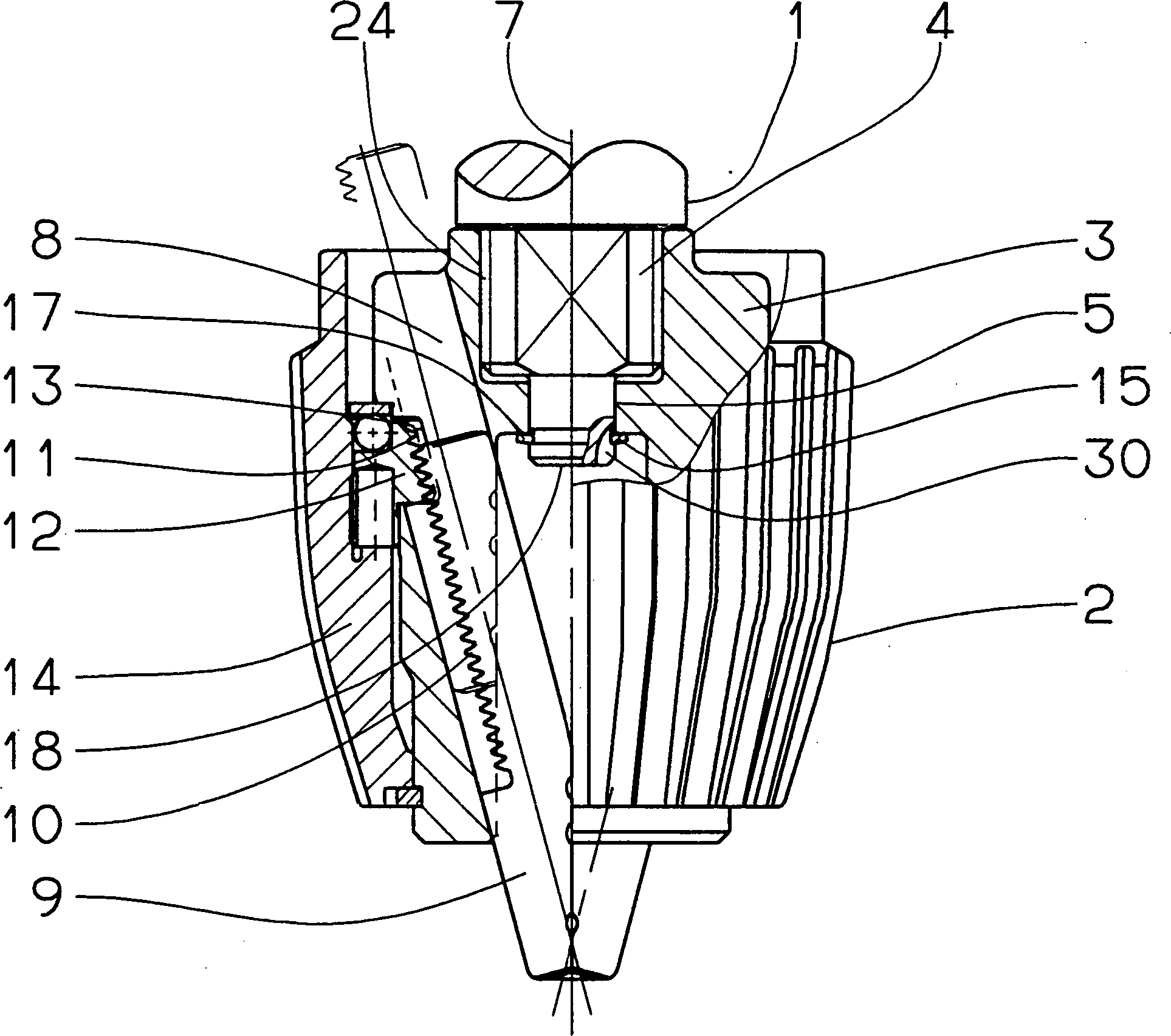
Bohrvorrichtung, bestehend aus einer eine Spindel (1) aufweisenden Bohrmaschine und einem Bohrfutter (2) mit einem Futterkörper (3), in dem an dessen der Spindel (1) zugewandtem Ende eine Spindelaufnahme (4) und an dem gegenüberliegenden Ende eine Werkzeugaufnahme (6) ausgebildet ist, dadurch gekennzeichnet, daß die Spindel (1) mit einem Sicherungsteil (15) in ihrer axialen Lage gegenüber dem Futterkörper (3) gesichert ist, und daß zur Drehmomentübertragung zwischen Bohrfutter (2) und Spindel (1) diese einen nicht-rotationssymmetrischen Abschnitt (16) aufweist, der mit einer am Futterkörper (3) ausgebildeten Drehaufnahme (22) drehfest gekoppelt ist.drilling, consisting of a spindle (1) having a drill and a chuck (2) with a chuck body (3), in which at the Spindle (1) facing the end of a spindle receptacle (4) and on the opposite End of a tool holder (6) is formed, characterized in that the spindle (1) with a securing part (15) in its axial position relative to the chuck body (3) is secured, and that the torque transmission between chuck (2) and spindle (1) this one non-rotationally symmetrical Section (16) with one on the chuck body (3) trained rotary holder (22) is rotatably coupled.
Description
Die Erfindung betrifft eine Bohrvorrichtung, bestehend aus einer eine Spindel aufweisenden Bohrmaschine und einem Bohrfutter mit einem Futterkörper, in dem an dessen der Spindel zugewandtem Ende eine Spindelaufnahme und an dem gegenüberliegenden Ende eine Werkzeugaufnahme ausgebildet ist.The The invention relates to a drilling device consisting of a Spindle having drill and a chuck with a Chuck body, in which at the end facing the spindle, a spindle receptacle and on the opposite End of a tool holder is formed.
Derartige Bohrvorrichtungen sind aus der Praxis bekannt, wobei die Kopplung von Bohrmaschine und Bohrfutter in der Regel über eine Gewindeverbindung erfolgt, bei der auf der Spindel ein Außengewinde und in der Spindelaufnahme ein Innengewinde ausgebildet ist. Diese Gewindeverbindung erfüllt die zweifache Funktion, die axiale Lage des Futterkörpers und damit des Bohrfutters gegenüber der Bohrmaschine zu sichern und zugleich eine drehfeste Verbindung herzustellen, über die das von der Bohrmaschine erzeugte Drehmoment übertragen werden kann. Ist jedoch die Bohrmaschine für den Rechts-/Linkslauf ausgelegt, ergibt sich das Problem, dass bei großem Bohrwiderstand in der dem Lösen des Bohrfutters entsprechenden Drehrichtung zusätzliche Sicherungen notwendig sind, um eine Trennung der Kopplung von Spindel und Bohrfutter zu verhindern.such Drilling devices are known in practice, wherein the coupling of drill and chuck usually via a threaded connection takes place, in which on the spindle an external thread and in the spindle receptacle an internal thread is formed. This thread connection fulfills the two-fold function, the axial position of the chuck body and thus of the chuck opposite the To secure drill and at the same time to produce a non-rotatable connection on the the torque generated by the drill can be transmitted. is however, the drill for designed the right / left rotation, the problem arises that at great Drilling resistance in the release of the Drill chucks corresponding direction of rotation additional fuses necessary are to prevent separation of the spindle and chuck coupling.
In
der
Der Erfindung liegt daher die Aufgabe zugrunde, die Kopplung von Bohrfutter und Spindel der Bohrmaschine weiter zu verbessern.Of the The invention is therefore based on the object, the coupling of chuck and spindle of the drill to further improve.
Diese Aufgabe wird bei einer Bohrvorrichtung der eingangs genannten Art dadurch gelöst, dass die Spindel mit einem Sicherungsteil in ihrer axialen Lage gegenüber dem Futterkörper gesichert ist, und dass zur Drehmomentübertragung zwischen Bohrfutter und Spindel diese einen nicht- rotationssymmetrischen Abschnitt aufweist, der mit einer am Futterkörper ausgebildeten Drehaufnahme drehfest gekoppelt ist.These Task is in a drilling device of the type mentioned solved by that the spindle with a securing part in its axial position relative to the chuck body is secured, and that for torque transmission between chuck and spindle this one non-rotationally symmetric Section having, which is formed with a chuck body on the rotary receptacle rotatably coupled.
Die Erfindung bietet den Vorteil, dass die axiale Lagesicherung des Bohrfutters und dessen Drehmitnahme separiert sind und die Übertragung des Drehmoments beim Bohrbetrieb nicht dazu führen kann, dass die Kopplung von Bohrfutter und Spindel sich löst oder das Bohrfutter in axialer Richtung gegenüber der Spindel verstellt wird.The Invention has the advantage that the axial position assurance of Drill chucks and its rotational drive are separated and the transmission The torque during drilling operation can not cause the coupling of chuck and spindle dissolves or the chuck in axial Direction opposite the spindle is adjusted.
Eine besonders bevorzugte Ausführungsform der Erfindung ist dadurch gekennzeichnet, dass im Futterkörper eine die Spindelaufnahme und die Werkzeugaufnahme verbindende Durchgangsöffnung und an der Spindel ein durch die Durchgangsöffnung hindurch ragender Spindelzapfen ausgebildet ist, an dem als das Sicherungsteil ein sich an dem Boden der Werkzeugaufnahme abstützender Sicherungsring befestigt ist. Bei dieser Ausführungsform bietet die aus Stahl gefertigte Spindel einen rückwärtigen axialen Anschlag für das Bohrwerkzeug, das somit auch in seiner axialen Lage festgelegt ist und nicht das Sicherungsteil schleichend oder auch schlagartig verschleißen oder zerstören kann.A particularly preferred embodiment the invention is characterized in that in the chuck body a the spindle receptacle and the tool holder connecting passage opening and on the spindle a through the through hole projecting spindle pin is formed, on which as the securing part is a on the ground the tool holder abstützender Circlip is attached. In this embodiment, the steel offers manufactured spindle a rear axial Stop for the drilling tool, which thus also fixed in its axial position is and not the security part creeping or abruptly wear out or destroy can.
Nach einer Alternative ist es möglich, daß der Sicherungsring in einer an dem Spindelzapfen ausgebildeten, in Umfangsrichtung verlaufenden Nut gehalten ist. Diese Ausführungsform bietet Kostenvorteile, und zwar sowohl hinsichtlich des Materialeinsatzes als auch bei der Fertigung. In axialer Richtung wird nur sehr wenig Platz beansprucht, so daß der Zapfen und die Spindel kurz ausgeführt werden können, was die Möglichkeit bietet, die Spindel in ihren rotationssymmetrischen Abschnitten mit einem Gewinde zu versehen und neben dem zu der Erfindung gehörenden Bohrfutter auch konventionelle Bohrfutter mit der Bohrmaschine koppeln zu können.To an alternative it is possible that the Circlip in a formed on the spindle pin, in the circumferential direction extending groove is held. This embodiment offers cost advantages, both in terms of material usage and in the production. In the axial direction only very little space is claimed, so that the Spigot and the spindle can be made short what the possibility provides the spindle in its rotationally symmetric sections to be provided with a thread and next to the invention belonging to drill chuck also to be able to couple conventional chuck with the drill.
Zweckmäßig ist es, wenn der Sicherungsring in axialer Richtung federnd ist, da durch dessen federnde Eigenschaften eine Zentrierung des Futterkörpers erfolgt, auch wenn der Spindelzapfen nicht in einem Paßsitz in der Durchgangsbohrung gehalten ist, was aber natürlich gleichfalls möglich ist. Durch die federnden Eigenschaften ist weiterhin sichergestellt, daß die Stirnseite der Spindel beim Übergang zum Spindelzapfen stets unter Spannung an dem Boden der Spindelaufnahme anliegt.Is appropriate it, if the retaining ring is resilient in the axial direction, there by whose resilient properties a centering of the chuck body takes place, even if the spindle pin is not in a snug fit in the through hole is held, but of course also possible is. Due to the resilient properties, it is furthermore ensured that that the front side the spindle at the transition to Spindle pin always under tension at the bottom of the spindle is applied.
Zum Lösen der Verbindung von Spindel und Bohrfutter ist am Spindelzapfen mindestens eine in axialer Richtung verlaufende, sich vom Rand bis zur Ringnut erstreckende Nut vorhanden, in die ein Stift zum Aufspreizen des Sicherungsringes eingeführt werden kann.To the Solve the Connection of spindle and chuck is at the spindle pin at least a running in the axial direction, from the edge to the annular groove extending groove present in a pin for spreading the Circlip are introduced can.
Die Befestigung des Sicherungsringes auf dem Spindelzapfen kann über eine Gewindeverbindung erfolgen, wozu vorgesehen ist, daß der Sicherungsring ein Innengewinde aufweist, das mit einem Außengewinde des Spindelzapfens zusammenwirkt. Dabei ist zu beachten, daß bei dieser Gewindeverbindung keine Drehmomentübertragung erfolgt und allein eine axiale Lagesicherung bei der Kopplung von Bohrfutter und Spindel bezweckt ist.The attachment of the retaining ring on the spindle pin can via a Gewindeverbin made tion, what is provided, that the locking ring has an internal thread, which cooperates with an external thread of the spindle pin. It should be noted that in this threaded connection no torque transmission takes place and only an axial position assurance in the coupling of chuck and spindle is intended.
Eine weitere Ausführungsform der Erfindung ist dadurch gekennzeichnet, daß an der Spindel der durch die Durchgangsöffnung hindurch ragende Spindelzapfen und zur Ausbildung einer Schnappverbindung an dem Spindelzapfen ein pilzkopf-förmiges Ende als Sicherungsteil ausgebildet ist, und daß die Durchgangsöffnung durch einen Ringbund verengt ist. Bei dieser Ausführungsform ist ein separates Sicherungsteil vermieden, das erst nach Durchstecken des Spindelzapfens durch die Durchgangsöffnung auf dem Spindelzapfen plaziert werden muß; vielmehr ist ein einfacher Steckvorgang ausreichend, um eine axial feste Kopplung zwischen Bohrfutter und Spindel herzustellen.A another embodiment the invention is characterized in that on the spindle of the passage opening through projecting spindle pin and to form a snap connection on the spindle pin a mushroom-shaped end as a security part is formed, and that the Through opening is narrowed by a collar. In this embodiment a separate security part is avoided, the only after plugging of the spindle journal through the passage opening on the spindle journal must be placed; much more is a simple mating process sufficient to an axially fixed Coupling between chuck and spindle produce.
Im Rahmen der Erfindung ist es weiterhin möglich, daß eine mit ihrem Schraubenkopf dem Boden der Werkzeugaufnahme anliegende Schraube als Sicherungsteil mit dem Spindelzapfen verschraubt ist.in the Under the invention, it is also possible that one with her screw head the bottom of the tool holder fitting screw as a security part screwed to the spindle pin.
Wenn die Spindel eine zum Rand hin geneigt verlaufende erste Keilfläche aufweist, an der eine dem Futterkörper zugeordnete zweite Keilfläche angreift, dann ist über die einander anliegenden Keilflächen, die dem nicht-rotationssymmetrischen Abschnitt der Spindel und der Drehaufnahme des Futterkörpers entsprechen, eine axiale Sicherung erreicht, deren Stärke über das gegenseitige Verschieben der Keilflächen eingestellt werden kann, wozu axiales Spiel zur Verfügung steht, um die eine Keilfläche gegenüber der anderen Keilfläche radial zu verschieben und die Spindel in einer Plananlage an dem Futterkörper zu halten.If the spindle has a first wedge surface extending inclined towards the edge, at one of the chuck body associated second wedge surface attacks, then is over the adjacent wedge surfaces, which is the non-rotationally symmetric section of the spindle and the Shooting of the chuck body correspond to an axial fuse whose strength exceeds that mutual displacement of the wedge surfaces can be adjusted for which axial play available stands around the one wedge surface across from the other wedge surface to move radially and the spindle in a plane contact with the chuck body hold.
Hinsichtlich der Einfachheit des Aufbaus ist bevorzugt, wenn die zweite Keilfläche an einem Sicherungsstift gebildet ist, der durch eine radiale, im Futterkörper zur Spindelaufnahme führende Bohrung ragt.Regarding the simplicity of construction is preferred when the second wedge surface on a Secured pin is formed by a radial, in the chuck body for Spindle holder leading Bore sticks out.
Für eine sichere, dauerhafte Verbindung ist es dann möglich, daß der Sicherungsstift in der Bohrung durch eine Gewindeverbindung radial festgelegt ist.For a safe, permanent connection, it is then possible that the locking pin in the Bore is defined radially by a threaded connection.
Nach einer alternativen Ausführungsform ist vorgesehen, daß eine der Keilflächen durch eine radial verschiebbare Kugel gebildet ist.To an alternative embodiment is provided that a the wedge surfaces is formed by a radially displaceable ball.
Das Ausmaß der radialen Verstellung der Kugel und damit die Haltekraft läßt sich einstellen, wenn die Kugel durch eine Feder beaufschlagt in Richtung der anderen Keilfläche gedrückt ist. Durch die Federkraft ist weiterhin eine gleichbleibende gute Plananlage der Spindel an dem Futterkörper gegeben.The Extent of radial adjustment of the ball and thus the holding force can be set when the ball is acted upon by a spring in the direction the other wedge surface depressed is. Due to the spring force is still a consistent good plan system the spindle on the chuck body given.
Zum Lösen der Verbindung von Spindel und Futterkörper ist in der Spindel ein radial verlaufendes, zur ersten Keilfläche führendes Langloch ausgebildet, das mit Löchern in der Stellhülse und dem Futterkörper fluchtet.To the Solve the Connection of spindle and chuck body is in the spindle formed radially extending, leading to the first wedge surface slot, with holes in the adjusting sleeve and the chuck body flees.
Eine weitere Alternative zur Befestigung der Spindel ist dadurch gekennzeichnet, daß an der Spindel ein Ring mit Rastzapfen befestigt ist, die in in der Spindel ausgebildeten Zapfenaufnahmen radial verstellbar sind und an dem Futterkörper ausgebildte Raststege hintergreifen.A Another alternative for fastening the spindle is characterized in that that on the spindle is attached to a ring with locking pins, which in in the Spindle trained pin receivers are radially adjustable and on the chuck body engage behind trained locking webs.
Zur Sicherung einer guten Plananlage der Spindel ist vorgesehen, daß die Rastzapfen mit Vorspannung den Raststegen anliegen.to Securing a good plan system of the spindle is provided that the locking pin with bias to rest the locking webs.
Eine sich durch die Einfachheit ihrer Gestaltung auszeichnende Spindel mit nicht-rotationssymmetrischem Abschnitt ist dadurch gegeben, daß an der Spindel mindestens eine Planfläche ausgebildet ist. Diese Planfläche und die dazu korrespondierende Planfläche in der Spindelaufnahme sind einfach herzustellen und gewährleisten damit eine bessere Paßgenauigkeit als bei komplizierter geformten Querschnittsprofilen von Spindel und Spindelaufnahme. Weist die Spindel weiterhin auch ein Gewinde auf, ist es gleichfalls möglich, konventionelle Bohrfutter mit einer Gewindeaufnahme an der Spindel zu befestigen.A characterized by the simplicity of their design distinguishing spindle with non-rotationally symmetric section is given by that at the Spindle at least one plane surface is trained. This plane surface and the corresponding plane surface in the spindle receptacle are easy to manufacture and thus ensure a better fit as with more complicated shaped cross-sectional profiles of spindle and spindle receptacle. If the spindle still has a thread, it is equally possible Conventional drill chuck with a threaded receptacle on the spindle to fix.
Um bei der Drehmomentübertragung eine geringere Belastung der Spindelaufnahme zu erreichen, ist auf der Planfläche der Spindel als Koppelglied eine Flügelscheibe drehfest befestigt, deren Flügel in der Drehaufnahme drehfest gehalten ist. Auf der Flügelscheibe kann auch die Spindel in ihrer Plananlage aufliegen. Um eine bessere Verteilung der Belastungt sowohl hinsichtlich des Drehmoments als auch in axialer Richtung beispielsweise im Schlagbohrbetrieb zu erreichen, weist die Flügelscheibe mehrere, gleichmäßig über den Umfang verteilte Flügel auf. An den Flügeln ist eine in axiale Richtung weisende Platte ausgebildet, in der der Sicherungsstift gehalten ist, der in eine Ringnut der Spindel eingreift und so eine axiale Sicherung bildet. Zur Ausbildung der Keilflächen weist die Nut geneigte Seitenwände und der Stift eine Konusspitze auf.Around in torque transmission to achieve a lower load on the spindle, is on the plane surface the spindle as a coupling member rotatably attached a wing disc, their wings is held against rotation in the rotary holder. On the wing disk can also rest the spindle in their plan system. To a better one Distribution of the load, both in terms of torque and in the axial direction, for example in impact drilling, the wing disc has several, evenly over the Circumference distributed wings on. At the wings is an axially facing plate formed in the the locking pin is held in an annular groove of the spindle engages and forms an axial securing. To the training of wedge surfaces the groove has inclined side walls and the pen on a cone tip.
Zur axialen Verbindung der Spindel und des Futterkörpers ist es auch möglich, daß in der Spindelaufnahme im Futterköper ein radial verlaufender Stiftkanal zur Aufnahme eines in eine Spindelöffnung einzusetzenden Sicherungsbolzens ausgebildet ist. Bevorzugt dabei ist, daß die Spindelöffnung durch die Spindelachse verläuft, und daß der Sicherungsbolzens mit seinen Rändern in die Drehaufnahmen eingreift. So ist mit dem Sicherungsbolzen sowohl die axiale als auch die Drehverbindung hergestellt, ohne daß im Bohrbetrieb eine Lockerung oder ein Lösen dieser Verbindungen droht.For axial connection of the spindle and the chuck body, it is also possible that in the spindle receptacle in the Futterköper a radially extending pin channel for receiving a to be used in a spindle opening securing bolt is formed. It is preferred that the spindle opening extends through the spindle axis, and that the securing bolt engages with its edges in the rotary receptacles. Thus, both the axial and the rotational connection is made with the safety bolt, without loosening or loosening of these compounds threatens in drilling operation.
Alternativ ist es möglich, die Verbindung von Bohrfutter und Spindel so vorzusehen, daß die Spindelaufnahme einen nicht-runden, vorzugsweise einen mehrkantigen Querschnitt und die Spindel eine dazu korrespondierende Querschnittsgestalt besitzt oder daß der Spindelzapfen und die Durchgangsöffnung eine aufeinander abgestimmte eckige Querschnittsform haben, oder daß der Spindelzapfen nach Art eines Torx-Steckers und die Durchgangsöffnung nach Art einer Torx-Buchse geformt ist.alternative Is it possible, to provide the connection of chuck and spindle so that the spindle receptacle a non-round, preferably a polygonal cross-section and the spindle has a corresponding cross-sectional shape owns or that the Spindle pin and the through hole have a coordinated angular cross-sectional shape, or that the Spindle pin in the manner of a Torx connector and the passage opening to Type of a Torx socket is shaped.
Die sich aus der Erfindung ergebenden Vorteile hinsichtlich der Separierung der axialen Lagesicherung und der Drehmomentübertragung sind besonders ausgeprägt, wenn der Futterkörper aus einem faserverstärkten Kunststoff besteht, bei dem eine zuverlässige Gewindeverbindung zwischen Spindel und Spindelaufnahme nur mit hohem Aufwand erreichbar ist, weil die einzelnen Gewindegänge gegenüber Beschädigungen anfälliger sind als bei vergleichbaren Futterkörpern aus Stahl.The resulting from the invention advantages in terms of separation the axial position assurance and torque transmission are particularly pronounced when the chuck body made of a fiber-reinforced Plastic consists of a reliable threaded connection between spindle and spindle mount is achievable only with great effort, because the single threads across from damage vulnerable are as in comparable chucks made of steel.
Im folgenden soll die Erfindung an in der Zeichnung dargestellten Ausführungsbeispielen näher erläutert werden; es zeigen:in the The following is intended to the invention in exemplary embodiments illustrated in the drawing be explained in more detail; show it:
Die
in der Zeichnung dargestellte Bohrvorrichtung besteht aus einer
Bohrmaschine, von der jedoch lediglich die für die Erläuterung der Erfindung relevante
Spindel
Bei
den in der Zeichnung dargestellten Bohrvorrichtungen ist die Kopplung
zwischen der Spindel
Nach
einer nicht gezeigten Ausführungsform ist
es aber gleichfalls möglich,
statt eines Sicherungsringes
Eine
weitere Ausführungsform
ist in den
Bei
den Bohrvorrichtungen gemäß den
In
den
In
den Zeichnungen ist dargestellt, daß eine der Keilflächen
Die
Kugel
In
den
Die
vorstehend geschilderten Bohrvorrichtungen zeichnen sich dadurch
aus, daß die
Kopplung zwischen Spindel
Die
Drehmomentübertragung
erfolgt, indem an der Spindel
Es
ist auch möglich,
die Ausdehnung der Planflächen
In
den
In
den
Die
Vorteile der erfindungsgemäßen Bohrvorrichtung
zeigen sich sowohl bei der Verwendung des bewährten Werkstoffes Stahl für Futterkörper
Claims (29)
Priority Applications (3)
| Application Number | Priority Date | Filing Date | Title |
|---|---|---|---|
| DE19829251A DE19829251B4 (en) | 1998-01-14 | 1998-06-30 | drilling |
| GB9900608A GB2333253B (en) | 1998-01-14 | 1999-01-12 | Drilling apparatus |
| BR9900054-7A BR9900054A (en) | 1998-01-14 | 1999-01-13 | Drilling machine. |
Applications Claiming Priority (3)
| Application Number | Priority Date | Filing Date | Title |
|---|---|---|---|
| DE19800999 | 1998-01-14 | ||
| DE19800999.2 | 1998-01-14 | ||
| DE19829251A DE19829251B4 (en) | 1998-01-14 | 1998-06-30 | drilling |
Publications (2)
| Publication Number | Publication Date |
|---|---|
| DE19829251A1 DE19829251A1 (en) | 1999-07-15 |
| DE19829251B4 true DE19829251B4 (en) | 2008-05-21 |
Family
ID=7854494
Family Applications (2)
| Application Number | Title | Priority Date | Filing Date |
|---|---|---|---|
| DE19829251A Expired - Fee Related DE19829251B4 (en) | 1998-01-14 | 1998-06-30 | drilling |
| DE19829931A Expired - Fee Related DE19829931C2 (en) | 1998-01-14 | 1998-07-04 | Drill chuck |
Family Applications After (1)
| Application Number | Title | Priority Date | Filing Date |
|---|---|---|---|
| DE19829931A Expired - Fee Related DE19829931C2 (en) | 1998-01-14 | 1998-07-04 | Drill chuck |
Country Status (2)
| Country | Link |
|---|---|
| DE (2) | DE19829251B4 (en) |
| GB (1) | GB2333254B (en) |
Families Citing this family (8)
| Publication number | Priority date | Publication date | Assignee | Title |
|---|---|---|---|---|
| DE10226429A1 (en) * | 2002-06-13 | 2003-12-24 | Roehm Gmbh | chuck |
| DE102004053783A1 (en) * | 2004-11-08 | 2006-05-11 | Robert Bosch Gmbh | Hand tool, in particular drill or screwdriver |
| US8459659B2 (en) * | 2007-12-19 | 2013-06-11 | Illinois Tool Works Inc. | Hybrid lathe chuck |
| DE102009028269A1 (en) | 2009-08-06 | 2011-02-10 | Robert Bosch Gmbh | The tool holder assembly |
| DE202012102742U1 (en) | 2012-07-23 | 2013-04-25 | Röhm Gmbh | chuck |
| DE102012112208A1 (en) * | 2012-12-13 | 2014-06-18 | Röhm Gmbh | chuck |
| DE102013108209B3 (en) * | 2013-07-31 | 2014-12-11 | Haimer Gmbh | tool holder |
| DE102023134201A1 (en) * | 2023-12-06 | 2025-06-12 | Röhm Gmbh | Drill chuck and drill |
Citations (2)
| Publication number | Priority date | Publication date | Assignee | Title |
|---|---|---|---|---|
| DE3400149C2 (en) * | 1984-01-04 | 1986-10-30 | Günter Horst 7927 Sontheim Röhm | Drill chucks for hammer drilling |
| DE4411524A1 (en) * | 1994-04-02 | 1995-10-05 | Roehm Guenter H | Drill chuck |
Family Cites Families (5)
| Publication number | Priority date | Publication date | Assignee | Title |
|---|---|---|---|---|
| US3910589A (en) * | 1974-03-06 | 1975-10-07 | Jacobs Mfg Co | Electrically insulated drill chuck for portable electric power drills |
| IT1077357B (en) * | 1977-03-14 | 1985-05-04 | Star Utensili Elett | SELF-CENTERING SPINDLE, IN PARTICULAR FOR PORTABLE ELECTRIC TOOLS |
| DE4208460A1 (en) * | 1992-03-17 | 1993-09-23 | Bosch Gmbh Robert | DRILL CHUCK FOR HAND MACHINE TOOLS |
| DE4307780A1 (en) * | 1993-03-12 | 1994-09-15 | Bosch Gmbh Robert | Drill chuck |
| DE59606508D1 (en) * | 1996-01-17 | 2001-04-05 | Roehm Gmbh | Drill chuck |
-
1998
- 1998-06-30 DE DE19829251A patent/DE19829251B4/en not_active Expired - Fee Related
- 1998-07-04 DE DE19829931A patent/DE19829931C2/en not_active Expired - Fee Related
-
1999
- 1999-01-12 GB GB9900610A patent/GB2333254B/en not_active Expired - Fee Related
Patent Citations (2)
| Publication number | Priority date | Publication date | Assignee | Title |
|---|---|---|---|---|
| DE3400149C2 (en) * | 1984-01-04 | 1986-10-30 | Günter Horst 7927 Sontheim Röhm | Drill chucks for hammer drilling |
| DE4411524A1 (en) * | 1994-04-02 | 1995-10-05 | Roehm Guenter H | Drill chuck |
Also Published As
| Publication number | Publication date |
|---|---|
| GB2333254A (en) | 1999-07-21 |
| DE19829931A1 (en) | 1999-07-22 |
| GB2333254B (en) | 2002-06-05 |
| DE19829251A1 (en) | 1999-07-15 |
| DE19829931C2 (en) | 2001-09-27 |
Similar Documents
| Publication | Publication Date | Title |
|---|---|---|
| EP2325502B1 (en) | Assembly and method for connecting an accessory with an operating table | |
| EP2792439B1 (en) | Quick change system for a tool holder | |
| WO1998051450A2 (en) | Tool system that can be coupled to a lathe drive shaft | |
| EP0501149A1 (en) | Fastening for securing a coupling sleeve | |
| DE102006028373A1 (en) | Separation point between two sub-elements of a rotating tool system | |
| DE2732677A1 (en) | COLLET | |
| DE3031216C2 (en) | Chuck for taps | |
| EP0391262B1 (en) | Clamping device to clamp axially a toolhead on a machine-tool spindle | |
| DE10028016A1 (en) | Keyless locking chuck used with drills or with electric or pneumatic power drivers, has collar between outer sleeve and chuck body to rotationally fix chuck body to power driver housing | |
| DE3020838C2 (en) | ||
| DE19829251B4 (en) | drilling | |
| EP0275441B1 (en) | Clamping device | |
| DE4143218C2 (en) | Device for connecting screwdriver bits | |
| EP3412388A1 (en) | Internal clamping means with secure clamping segment ring | |
| DE102014106082B4 (en) | drill chuck | |
| WO1993011890A1 (en) | Device for inserting and setting self-drilling blind tension rivets | |
| DE2335865A1 (en) | CHUCK FOR IMPACT DRILLS OR DRILLS | |
| DE102013108999A1 (en) | Tool holder for thermal shrinkage attachment of tools, is formed with radial through hole in case by extending from outer side of base to retainer, and is provided with driver which is penetrated to main cutting face | |
| DE4134405A1 (en) | DEVICE FOR ATTACHING A CUTTING TOOL TO A CUTTING MACHINE | |
| DE1602760A1 (en) | Boring bar insert for adjustable holding of a tool in selected positions in a boring bar | |
| DE19918638C2 (en) | Connector for a drill for drilling holes in bone tissue, drill and drill | |
| EP3824193B1 (en) | Insert for connecting an electric connection to a wall, disassembly tool, and aligning tool for an insert, and method for repairing an insert | |
| EP0561395B1 (en) | Chuck | |
| DE4342765A1 (en) | Drill chuck esp. for hammer drilling | |
| DE3839663C2 (en) |
Legal Events
| Date | Code | Title | Description |
|---|---|---|---|
| 8110 | Request for examination paragraph 44 | ||
| 8364 | No opposition during term of opposition | ||
| 8339 | Ceased/non-payment of the annual fee |