Die
vorliegende Erfindung bezieht sich auf ein hydraulisches Steuersystem
für ein
Automatikgetriebe. Insbesondere bezieht sie sich auf ein hydraulisches
Steuersystem für
ein Automatikgetriebe, wobei das hydraulische Steuersystem einen
Ausgangsdruck mit einem unterschiedlichen Verstärkungsfaktor steuert, der sich
auf einen Signaldruck bezieht.The
The present invention relates to a hydraulic control system
for a
Automatic transmission. In particular, it relates to a hydraulic
Control system for
an automatic transmission, wherein the hydraulic control system a
Output pressure with a different gain controls, which is
refers to a signal pressure.
Im
allgemeinen gibt ein Linearmagnetventil in einem herkömmlichen
hydraulischen Steuersystem für
ein Automatikgetriebe einen Signaldruck aus, der Signaldruck wird
in ein primäres
Regelventil eingegeben und das primäre Regelventil regelt einen Leitungsdruck
auf einen Ausgangsdruck, der in geeigneter Weise auf dem Signaldruck
basiert. Anschließend
werden viele Steuerarten basierend auf dem Ausgangsdruck durchgeführt. Eine
Veränderungsrate
des Ausgangsdrucks von dem primären Regelventil,
die sich auf eine Veränderung
des Signaldruckausgangs von dem linearen Solenoidventil bezieht,
wird unter Verwendung eines Verstärkungsfaktors vorgenommen,
der von nun an Verstärkung genannt
wird. Die Verstärkung
wird so festgelegt, daß der
Leitungsdruck auf den Ausgangsdruck eingeregelt wird, der für die hydraulische
Steuerung innerhalb des Bereiches des Signaldrucks benötigt wird, der
von den linearen Magnet- bzw. Solenoidventilen ausgegeben wird.
Das heißt,
die Verstärkung
wird so festgesetzt, daß der
Veränderungsbereich
des Ausgangsdrucks innerhalb des Veränderungsbereichs des Signaldrucks
erreicht wird.in the
general there is a linear solenoid valve in a conventional
hydraulic control system for
an automatic transmission turns off a signal pressure that becomes signal pressure
in a primary
Control valve input and the primary control valve regulates a line pressure
to an output pressure, suitably at the signal pressure
based. Subsequently
Many types of taxes are performed based on the output pressure. A
rate of change
the output pressure from the primary control valve,
focusing on a change
the signal pressure output from the linear solenoid valve relates
is done using a gain factor,
from now on called reinforcement
becomes. The reinforcement
is set so that the
Line pressure is adjusted to the output pressure, which is for the hydraulic
Control is needed within the range of signal pressure, the
is output from the linear solenoid valves.
This means,
the reinforcement
is set so that the
Altering area
the output pressure within the change range of the signal pressure
is reached.
Beispielsweise
wird in einem kontinuierlich variablen Getriebe, das eine stufenlose
Schaltung durch Verändern
eines Riemenscheibenverhältnisses
zwischen zwei Riemenscheiben, die mit einem Riemen verbunden sind,
durchführt,
ein ungewöhnlich
hoher Ausgangsdruck benötigt.
Das heißt,
bei einem solchen kontinuierlich variablen Getriebe wird das Riemenscheibenverhältnis durch
Zunehmen und Abnehmen einer Spannung auf den Riemen durch eine fixierte
Antriebsscheibe und eine bewegliche Antriebsscheibe geändert, die
jede Riemenscheibe aufweist. Die Spannung auf dem Riemen muß sich über einen
weiten Bereich verändern.
Deshalb ist es notwendig, daß sich
der Ausgangsdruck von dem primären
Regelventil zur Erzielung der Spannung auf den Riemen über den
weiten Bereich über
einen weiten Bereich verändert.
Als ein Weg zum Erzielen des weiten Veränderungsbereiches des Ausgangsdrucks kann
der Bereich des Signaldrucks groß gemacht werden. In diesem
Fall muß das
lineare Solenoidventil groß sein,
um den weiten Veränderungsbereich
für den
Signaldruck zu erzielen. Deshalb wird ein großer Raum zum Positionieren
des großen
linearen Solenoidventils benötigt
und die Kosten steigen an.For example
is in a continuously variable transmission that has a stepless
Switching by changing
a pulley ratio
between two pulleys connected to a belt,
performs,
an unusual one
high output pressure required.
This means,
in such a continuously variable transmission, the pulley ratio is through
Increasing and decreasing a tension on the strap through a fixed
Drive pulley and a movable drive pulley changed that
each pulley has. The tension on the belt must go over one
change wide range.
That's why it's necessary that yourself
the outlet pressure from the primary
Control valve to provide tension on the belt over the
wide area over
changed a wide range.
As a way to achieve the wide range of variation of the outlet pressure can
the range of the signal pressure is made large. In this
Case has that
be a linear solenoid valve,
around the wide range of change
for the
To achieve signal pressure. That's why there's a lot of room for positioning
of the big one
linear solenoid valve needed
and the costs increase.
Als
anderer Weg zur Erzielung des weiten Veränderungsbereiches des Ausgangsdrucks
unter Berücksichtigung
der vorstehend beschriebenen Nachteile, ist es möglich, den Verstärkungsfaktor groß zu machen.
In diesem Fall, wenn der Verstärkungsfaktor
groß ist,
ist die Veränderung
des Ausgangsdrucks, die sich auf die Veränderung des Signaldrucks bezieht,
groß.
Anschließend
wird jedoch die Streuung des Ausgangsdrucks aufgrund der Vibration
im Signaldruck groß.
Deshalb ist es schwierig, eine hohe Genauigkeitssteuerung für den Ausgangsdruck
zu erreichen. Das heißt,
für den
Fall, wo der Veränderungsbereich
des Signaldrucks stabil ist, wird der Veränderungsbereich des Ausgangsdrucks groß und der
hohe Ausgangsdruck wird erreicht, wenn der Verstärkungsfaktor so eingestellt
ist, daß er groß ist, aber
die eine hochgenaue Steuerung des Ausgangsdrucks ist schwierig.
Wenn der Verstärkungsfaktor
eingestellt wird, um klein zu sein, wird eine hochgenaue Steuerung
hinsichtlich des Ausgangsdrucks erreicht, aber der Veränderungsbereich des
Ausgangsdrucks wird klein und der notwendige hohe Ausgangsdruck
wird nicht erreicht.When
Another way to achieve the wide range of change of the outlet pressure
considering
Of the disadvantages described above, it is possible to make the gain large.
In this case, if the gain factor
is great
is the change
the outlet pressure, which refers to the change in signal pressure,
large.
Subsequently
However, the dispersion of the output pressure due to the vibration
big in signal pressure.
Therefore, it is difficult to have high accuracy control for the output pressure
to reach. This means,
for the
Case where the change area
of the signal pressure is stable, the variation range of the output pressure becomes large and the
high output pressure is achieved when the gain is adjusted
is that he is big, but
the highly accurate control of the outlet pressure is difficult.
When the gain factor
is set to be small, becomes a high-precision control
reached with respect to the outlet pressure, but the range of change of
Output pressure is small and the necessary high output pressure
will not be reached.
Tatsächlich benötigt das
in ein Fahrzeug montierte vorstehend beschriebene kontinuierlich
variable Getriebe den großen
Ausgangsdruck beispielsweise bei dem Fahrzeugstart, weil das Riemenscheibenverhältnis stark
verändert
werden muß. Und,
beispielsweise während
einer beständigen Fahrgeschwindigkeit
benötigt
das kontinuierlich variable Getriebe einen kleinen Ausgangsdruck,
beispielsweise zum Zwecke der Minimierung des Kraftstoffverbrauchs
und der Aufrechterhaltung einer hochgenauen Steuerung des Ausgangsdrucks.
Das heißt,
in dem kontinuierlich variablen Getriebe ist ein geringer Verstärkungsfaktor
geeignet, wenn das kontinuierlich variable Getriebe eine geringe
Ausgangsleistung benötigt.
Wenn das kontinuierlich variable Getriebe eine hohe Ausgangsleistung
benötigt,
ist ein großer
Verstärkungsfaktor
geeignet.In fact, that requires
in a vehicle mounted as described above continuously
variable transmission the big one
Output pressure, for example, at the vehicle start, because the pulley ratio strong
changed
must become. And,
for example during
a constant driving speed
needed
the continuously variable transmission has a small output pressure,
for example, for the purpose of minimizing fuel consumption
and maintaining a high accuracy control of the output pressure.
This means,
in the continuously variable transmission is a low gain factor
suitable if the continuously variable transmission is a low
Output power needed.
When the continuously variable transmission has a high output power
needed
is a big
gain
suitable.
Die
linearen Magnetventile und Regelventile haben Streuungen, die beispielsweise
durch die Herstellgenauigkeit und die Montagegenauigkeit der Ventilkörper und
der Spulenkörper
hervorgerufen werden, und von der Federlast der Feder, die die Spulenkörper in
jeder Montageeinheit belasten. Deshalb haben der Signaldruck von
den linearen Magnetventilen und die Steuerdrücke von den Regelventilen eine
Streuung bzgl. demselben Stromwert in jedem Hydraulikkreislauf.
Das heißt,
der Steuerdruck als Ausgang, bezogen auf den Stromwert als Eingang,
hat einen Streuungsgrad.The
linear solenoid valves and control valves have scatters, for example
by the manufacturing accuracy and mounting accuracy of the valve body and
the bobbin
be caused, and by the spring load of the spring, the bobbin in
load each assembly unit. Therefore, the signal pressure of
the linear solenoid valves and the control pressures from the control valves a
Scattering with respect to the same current value in each hydraulic circuit.
This means,
the control pressure as output, based on the current value as input,
has a degree of dispersion.
Zur
Reduzierung der Streuung in jedem Hydraulikkreislauf ist ein Einstellmechanismus
in dem linearen Magnetventil angeordnet. Als Einstellmechanismus
wird beispielsweise eine Einstellschraube zum Erhöhen oder
Vermindern der Federlast der Feder, die den Spulenkörper belastet,
verwendet. In diesem Fall kann die Federlast durch die Einstellschraube
in jedem Hydraulikkreis erhöht
und vermindert werden, und anschließend werden der Signaldruck und
der Steuerdruck bezogen auf den Signaldruck geregelt. Dadurch wird
der geeignete Steuerdruck erreicht.To reduce the dispersion in each hydraulic circuit, an adjustment mechanism is disposed in the linear solenoid valve. As the adjusting mechanism, for example, an adjusting screw for increasing or decreasing the spring load of the spring loading the bobbin is used. In the In this case, the spring load can be increased and decreased by the adjusting screw in each hydraulic circuit, and then the signal pressure and the control pressure are controlled with respect to the signal pressure. As a result, the appropriate control pressure is achieved.
12 zeigt ein Beispiel zur
Regelung des Steuerdrucks aus dem Stand der Technik. 12 zeigt eine lineare Veränderung
des Steuerdrucks PL, wobei die Streuung hinsichtlich der Stromwerte
I der linearen Magnetventile in verschiedenen Hydraulikkreisen festgestellt
wurde. In 12 zeigt die
durchgehende Linie A einen Sollwert, die obere Seite der abwechselnden
lang und zweimal kurz gestrichelten Linie a1 zeigt einen Maximalwert
der Streuung vor der Einstellung, eine untere Seite der abwechselnd lang
und zweimal kurz gestrichelten Linie a2 zeigt einen Minimalwert
der Streuung vor der Einstellung, eine obere Seite der abwechselnd
lang und kurz gestrichelten Linie b1 zeigt einen Maximalwert der Streuung
nach der Einstellung und eine untere Seite der lang und kurz gestrichelten
Linie b2 zeigt einen Minimalwert der Streuung nach der Einstellung. 12 shows an example for controlling the control pressure from the prior art. 12 shows a linear change of the control pressure PL, wherein the dispersion was determined with respect to the current values I of the linear solenoid valves in various hydraulic circuits. In 12 the solid line A indicates a target value, the upper side of the alternate long and short dashed line a1 shows a maximum value of the dispersion before the adjustment, a lower side of the alternate long and two short dashed line a2 indicates a minimum value of the dispersion before the adjustment, an upper side of the alternate long and short dashed line b1 shows a maximum value of the dispersion after the adjustment, and a lower side of the long and short dashed line b2 shows a minimum value of the dispersion after the adjustment.
Der
Steuerdruck PL wird wie folgt eingestellt.Of the
Control pressure PL is set as follows.
Beim
Stand der Technik wird ein Einstellpunkt (Basispunkt) auf einer
Niederdruckseite des Steuerdrucks PL festgesetzt und der Steuerdruck
PL wird so geregelt, daß der
Steuerdruck PL ein vorbestimmter Steuerdruck PA ist. Tatsächlich wird
der Stromwert des linearen Solenoids auf einem vorbestimmten Wert
aufrechterhalten. Dann, während
dem Beobachten des Steuerdruckausgangs von dem Regelventil, wird
ein Schubbetrag der Einstellschraube eingestellt und die Einstellung
wird beendet, wenn der Steuerdruck PL den vorbestimmten Steuerdruck PA
erreicht.At the
The prior art becomes a set point (base point) on a
Low pressure side of the control pressure PL set and the control pressure
PL is regulated so that the
Control pressure PL is a predetermined control pressure PA. Actually
the current value of the linear solenoid at a predetermined value
maintained. Then, while
observing the control pressure output from the control valve
adjusted a thrust amount of the adjusting screw and the setting
is terminated when the control pressure PL the predetermined control pressure PA
reached.
Beim
Einstellen von der oberen Seite der abwechselnd lang und zweimal
kurz gestrichelten Linie a1, nimmt der Belastungsbetrag der Einstellschraube zu
und das linke Ende der Linie a1 wird auf den vorbestimmten Steuerdruck
PA festgesetzt. Beim Einstellen von der unteren Seite der abwechselnd
lang und zweimal kurz gestrichelten Linie a2 ist der Belastungsbetrag
der Einstellschraube vermindert und das linke Ende der Linie a2
wird auf den vorbestimmten Steuerdruck PA festgesetzt. Durch dieses
Verfahren werden die Linien a1 und a2 parallel versetzt und auf die
Linien b1, b2 verschoben.At the
Adjust from the upper side of the alternately long and twice
short dashed line a1, the load amount of the adjusting screw increases
and the left end of the line a1 becomes the predetermined control pressure
PA stated. When adjusting the lower side of the alternating
long and twice short dashed line a2 is the debit amount
the adjusting screw decreases and the left end of the line a2
is set to the predetermined control pressure PA. Because of this
Method, the lines a1 and a2 are offset in parallel and on the
Lines b1, b2 shifted.
Durch
die Durchführung
der Einstellung für jeden
Hydraulikkreis, wird der vorbestimmte Steuerdruck PA für den vorbestimmten
Stromwert des linearen Magnetventils in jedem hydraulischen Kreis
erreicht. Das heißt,
der vorbestimmte Steuerdruck wird festgesetzt, um dem vorbestimmten
Stromwert zu entsprechen.By
the implementation
the setting for everyone
Hydraulic circuit, the predetermined control pressure PA for the predetermined
Current value of the linear solenoid valve in each hydraulic circuit
reached. This means,
the predetermined control pressure is set to be the predetermined one
Current value to correspond.
Jedoch
ist im Stand der Technik die Streuung nach der Einstellung groß, wenn
der Steuerdruck PL hoch ist, weil der Einstellpunkt für die Niederdruckseite
des Steuerdrucks PL festgesetzt ist. Deshalb ist der hydraulische
Druck, der ausgegeben werden kann, im Vergleich zum Sollwert A,
der in 12 gezeigt ist,
zu groß.
Als ein Ergebnis ist es notwendig, die Festigkeit und Zuverlässigkeit
des hydraulischen Kreises zu berücksichtigen,
wenn sich ein solcher hoher Druck ergibt.However, in the prior art, the dispersion after the adjustment is large when the control pressure PL is high, because the set point for the low pressure side of the control pressure PL is set. Therefore, the hydraulic pressure that can be output compared to the set point A, the in 12 shown is too big. As a result, it is necessary to consider the strength and reliability of the hydraulic circuit when such a high pressure results.
Umgekehrt,
wenn der Einstellpunkt an der Hochdruckseite des Steuerdrucks PL
festgesetzt wird, wird die Streuung an dem Einstellpunkt auf der Hochdruckseite
reduziert, aber die Streuung auf der Niederdruckseite wird erhöht. Deshalb
ist es notwendig, den untersten Steuerdruck so hoch festzusetzen, daß der Steuerdruck
für die
große
Streuung auf der Niederdruckseite ausreicht.Vice versa,
when the set point on the high pressure side of the control pressure PL
is set, the scattering is at the set point on the high-pressure side
reduced, but the dispersion on the low pressure side is increased. Therefore
it is necessary to set the lowest control pressure so high that the control pressure
for the
size
Scattering on the low pressure side is sufficient.
Wenn
der Einstellpunkt des Steuerdrucks PL auf der Niederdruckseite festgesetzt
wird, wird die Streuung an der Hochdruckseite erhöht, und
wenn der Einstellpunkt des Steuerdrucks PL auf der Hochdruckseite
festgesetzt wird, wird die Streuung auf der Niederdruckseite erhöht. Das
heißt,
die Streuung des Steuerdrucks PL wird auf einer Seite, die von dem Einstellpunkt
weit entfernt ist, erhöht,
weil die Einstellung durch die Einstellschraube nicht die Schleife
der Linien in 12 verändert, sondern
sie gerade parallel versetzt.When the set point of the control pressure PL on the low pressure side is set, the dispersion on the high pressure side is increased, and when the set point of the control pressure PL on the high pressure side is set, the dispersion on the low pressure side is increased. That is, the dispersion of the control pressure PL is increased on a side far from the set point, because the adjustment by the adjusting screw does not increase the loop of the lines in FIG 12 changed, but just offset them in parallel.
DE 697 08 754 T2 zeigt
ein hydraulisches Regelsystem für
ein Automatikgetriebe mit einer Signaldruckausgabevorrichtung, die
einen ersten Signaldruck ausgibt, sowie einer Regelvorrichtung,
die einen Ausgabedruck an ein Paar von hydraulischen Stellzylindern
ausgibt. DE 697 08 754 T2 shows a hydraulic control system for an automatic transmission with a signal pressure output device that outputs a first signal pressure, and a control device that outputs an output pressure to a pair of hydraulic adjusting cylinders.
Es
ist eine Aufgabe der vorliegenden Erfindung, ein hydraulisches Steuersystem
für ein
automatisches Getriebe zu schaffen, das sowohl eine hohe Steuergenauigkeit
für einen
Ausgangsdruck als auch einen hohen Ausgangsdruck durch Verändern eines
Verstärkungsfaktors,
der sich auf eine Veränderung
des Signaldrucks bezieht, erzielt, und die Streuung des Ausgangsdrucks,
der ein Steuerdruck ist, durch Festsetzen von zwei Einstellpunkten
reduziert.It
It is an object of the present invention to provide a hydraulic control system
for a
to create automatic transmission that has both high control accuracy
for one
Output pressure as well as a high output pressure by changing a
Gain,
focusing on a change
of the signal pressure achieved, and the dispersion of the outlet pressure,
which is a control pressure by setting two set points
reduced.
Die
vorstehende Aufgabe wird erfindungsgemäß mit einem hydraulischen Regelsystem
gemäß den Ansprüchen 1 und
8 gelöst.
Vorteilhafte Ausgestaltungen sind Bestandteil der Unteransprüche.The
The above object is achieved according to the invention with a hydraulic control system
according to claims 1 and
8 solved.
Advantageous embodiments are part of the dependent claims.
Ein
hydraulisches Steuersystem für
ein Automatikgetriebe gemäß einem
ersten Aspekt der Erfindung weist eine Signaldruckausgabevorrichtung
auf, die einen ersten Signaldruck ausgibt, eine Verstärkungsfaktorveränderungsvorrichtung,
die den ersten Signaldruck von der Signaldruckausgabevorrichtung empfängt und
einen zweiten Signaldruck basierend auf dem ersten Signaldruck ausgibt,
und eine Regelvorrichtung, die den zweiten Signaldruck von der Verstärkungsfaktorveränderungsvorrichtung
empfängt
und einen Ausgangsdruck regelt, der auf dem zweiten Signaldruck
basiert. Die Verstärkungsfaktorveränderungsvorrichtung
verändert
den Verstärkungsfaktor,
der die Veränderungsrate
des Ausgangsdrucks bezüglich
der Veränderung
des ersten Signaldrucks darstellt, auf einen niedrigen Verstärkungsfaktor
und einen hohen Verstärkungsfaktor
innerhalb eines Veränderungsbereichs
des ersten Signaldrucks. Die Verstärkungsfaktorveränderungsvorrichtung
weist ein Verstärkungsfaktorsteuerventil
auf, das einen Verstärkungsdruck
ausgibt, der basierend auf dem ersten Signaldruck geregelt wird,
und eine Auswahlvorrichtung, die den zweiten Signaldruck von dem
ersten Signaldruck auswählt
und den Verstärkungsdruck,
basierend auf deren Stärke.A hydraulic control system for an automatic transmission according to a first aspect of the invention includes a signal pressure output device that outputs a first signal pressure, a gain changing device that controls the first Receives signal pressure from the signal pressure output device and outputs a second signal pressure based on the first signal pressure, and a control device that receives the second signal pressure from the gain adjustment device and controls an output pressure based on the second signal pressure. The gain changing means changes the amplification factor, which represents the rate of change of the output pressure with respect to the change of the first signal pressure, to a low amplification factor and a high amplification factor within a variation range of the first signal pressure. The gain changing device includes a gain control valve that outputs a boost pressure that is controlled based on the first signal pressure, and a selector that selects the second signal pressure from the first signal pressure and the boost pressure based on the magnitude thereof.
Die
Auswahlvorrichtung weist ein Absperrkugelventil auf, das den höheren Druck
von dem ersten Signaldruck und dem Verstärkungsdruck als den zweiten
Signaldruck auswählt
und den zweiten Signaldruck an die Regelvorrichtung ausgibt.The
Selection device has a shut-off ball valve, which is the higher pressure
of the first signal pressure and the boost pressure as the second one
Signal pressure selects
and outputs the second signal pressure to the control device.
Der
erste Signaldruck wird als zweiter Signaldruck in die Regelvorrichtung
eingegeben und der Verstärkungsfaktor
wird auf den unteren Verstärkungsfaktor
verändert,
wenn der erste Signaldruck von der Signaldruckausgabevorrichtung
niedriger ist, als ein vorbestimmter Wert, und der Verstärkungsfaktordruck,
der höher
als der erste Signaldruck ist, wird als zweiter Signaldruck zur
Regulierungsvorrichtung eingegeben und der Verstärkungsfaktor wird auf den hohen
Verstärkungsfaktor
verändert,
wenn der erste Signaldruck von der Signaldruckausgabevorrichtung höher als
der vorbestimmte Wert ist.Of the
first signal pressure is used as the second signal pressure in the control device
entered and the gain factor
will be at the lower amplification factor
changed
when the first signal pressure from the signal pressure output device
is lower than a predetermined value, and the gain pressure,
the higher
when the first signal pressure is, as the second signal pressure to
Regulator is input and the gain is set to the high
gain
changed
when the first signal pressure from the signal pressure output device is higher than
is the predetermined value.
Das
Verstärkungssteuerventil
regelt den Ausgangsdruck, der durch die Regelvorrichtung geregelt
wird, auf den Verstärkungsfaktordruck.
Das Verstärkungsfaktorsteuerventil
regelt den Verstärkungsfaktordruck
von niedrig nach hoch, wenn der erste Signaldruck von einem niedrigen
zu einem hohen verändert.The
Gain control valve
regulates the outlet pressure regulated by the control device
is, on the gain of the pressure.
The gain control valve
regulates the gain pressure
from low to high, when the first signal pressure from a low
changed to a high one.
Das
hydraulische Steuersystem für
ein Automatikgetriebe weist einen ersten Einstellmechanismus auf,
der den ersten Signaldruck durch Einstellen der Signaldruckausgabevorrichtung
regelt, und einen zweiten Einstellmechanismus, der den Verstärkungsfaktordruck
durch Einstellen des Verstärkungsfaktorsteuerventils
regelt. Der erste Einstellmechanismus regelt den ersten Signaldruck,
der auf einem Basispunkt auf einer Niederdruckseite des Ausgangsdrucks
von der Regelvorrichtung basiert, und der zweite Einstellmechanismus
regelt den Verstärkungsfaktordruck
basierend auf einem Basispunkt auf einer Hochdruckseite des Ausgangsdrucks
von der Regelvorrichtung.The
hydraulic control system for
an automatic transmission has a first adjustment mechanism,
the first signal pressure by adjusting the signal pressure output device
regulates, and a second adjustment mechanism, the gain of the pressure
by adjusting the gain control valve
regulates. The first adjustment mechanism regulates the first signal pressure,
that on a base point on a low pressure side of the outlet pressure
based on the control device, and the second adjustment mechanism
regulates the gain pressure
based on a base point on a high pressure side of the outlet pressure
from the control device.
Die
Einstellung für
den ersten Signaldruck durch den ersten Einstellmechanismus wird
früher durchgeführt als
die Einstellung für
den Verstärkungsfaktordruck
durch den zweiten Einstellmechanismus.The
Setting for
the first signal pressure through the first adjustment mechanism becomes
performed earlier than
the setting for
the gain pressure
through the second adjustment mechanism.
Ein
hydraulisches Steuersystem für
ein Automatikgetriebe gemäß einem
zweiten Aspekt der Erfindung weist eine Signaldruckausgabevorrichtung auf,
die einen ersten Signaldruck ausgibt, eine Verstärkungsfaktoränderungsvorrichtung,
die den ersten Signaldruck von der Signaldruckausgabevorrichtung empfängt und
einen zweiten Signaldruck ausgibt, der auf dem ersten Signaldruck
basiert, und eine Regelvorrichtung, die den zweiten Signaldruck
von der Verstärkungsfaktoränderungsvorrichtung
empfängt und
einen Ausgabedruck regelt, basierend auf dem zweiten Signaldruck.
Die Verstärkungsfaktoränderungsvorrichtung ändert einen
Verstärkungsfaktor, der
die Änderungsrate
des Ausgangsdrucks in Bezug zur Änderung
des ersten Signaldrucks ist, auf einen niedrigen Verstärkungsfaktor
und einen hohen Verstärkungsfaktor
innerhalb eines Änderungsbereiches des
ersten Signaldrucks. Die Verstärkungsfaktoränderungsvorrichtung
weist ein Verstärkungsregelungsventil
auf, das einen Verstärkungsdruck
ausgibt, der basierend auf dem ersten Signaldruck geregelt wird.
Die Verstärkungsfaktoränderungsvorrichtung
gibt den ersten Signaldruck als den zweiten Signaldruck an die Regelvorrichtung
aus, wenn der erste Signaldruck niedriger als ein vorbestimmter
Wert ist, und die Verstärkungsfaktoränderungsvorrichtung gibt
sowohl den ersten Signaldruck als auch den Verstärkungsdruck als den zweiten
Signaldruck an die Regelvorrichtung aus, wenn der erste Signaldruck höher als
oder gleich dem vorbestimmten Wert ist.One
hydraulic control system for
an automatic transmission according to a
second aspect of the invention comprises a signal pressure output device,
which outputs a first signal pressure, a gain adjusting device,
which receives the first signal pressure from the signal pressure output device and
outputs a second signal pressure which is at the first signal pressure
based, and a control device, the second signal pressure
from the gain-factor changing device
receives and
controls an output pressure based on the second signal pressure.
The gain changing device changes one
Gain factor, the
the rate of change
the outlet pressure in relation to the change
of the first signal pressure is at a low gain
and a high gain
within a range of change of the
first signal pressure. The gain-factor changing device
has a gain control valve
on, that's a boost pressure
which is controlled based on the first signal pressure.
The gain-factor changing device
Gives the first signal pressure as the second signal pressure to the control device
when the first signal pressure is lower than a predetermined one
Is value, and the gain factor changing device gives
both the first signal pressure and the boost pressure as the second
Signal pressure to the control device off when the first signal pressure higher than
or equal to the predetermined value.
Das
Verstärkungsregelungsventil
regelt den Ausgangsdruck, der durch die Regelvorrichtung geregelt
wird, auf den Verstärkungsdruck.
Das Verstärkungsregelungsventil
regelt den Verstärkungsdruck von
einem niedrigen zu einem hohen, wenn sich der erste Signaldruck
von einem niedrigen zu einem hohen verändert.The
Gain control valve
regulates the outlet pressure regulated by the control device
will, on the boost pressure.
The gain control valve
regulates the boost pressure of
a low to a high when the first signal pressure
changed from a low to a high one.
Das
hydraulische Steuersystem für
ein Automatikgetriebe weist einen ersten Einstellmechanismus auf,
der den ersten Signaldruck durch Einstellen der Signaldruckausgabevorrichtung
regelt, und einen zweiten Einstellmechanismus, der den Verstärkungsdruck
durch Einstellen des Verstärkungsregelungsventils
regelt. Der erste Einstellmechanismus regelt den ersten Signaldruck
basierend auf einem Basispunkt auf einer Niederdruckseite des Ausgangsdrucks
von der Regelvorrichtung, und der zweite Einstellmechanismus regelt
den Verstärkungsdruck
basierend auf einem Basispunkt auf einer Hochdruckseite des Ausgangsdrucks
von der Regelvorrichtung. Die Einstellung für den ersten Signaldruck durch
den ersten Einstellmechanismus wird früher durchgeführt als
die Einstellung für
den Verstärkungsdruck
durch den zweiten Einstellmechanismus.The automatic transmission hydraulic control system has a first adjustment mechanism that regulates the first signal pressure by adjusting the signal pressure output device, and a second adjustment mechanism that regulates the boost pressure by adjusting the boost control valve. The first adjustment mechanism controls the first signal pressure based on a base point on a low pressure side of the output pressure from the control device, and the second adjustment mechanism controls the boost pressure based on a base point on a high pressure side of the outlet pressure from the control device. The setting for the first signal pressure by the first adjusting mechanism is performed earlier than the setting for the boosting pressure by the second adjusting mechanism.
Gemäß dem hydraulischen
Steuersystems des ersten Aspekts ändert sich der Verstärkungsfaktor
(Verstärkung)
des Ausgangsdrucks bezogen auf den ersten Signaldruck durch die
Verstärkungsfaktoränderungsvorrichtung
auf einen niedrigen Verstärkungsfaktor.
Deshalb wird die Änderung
des Ausgangsdrucks bezogen auf den ersten Signaldruck reduziert.
Als ein Ergebnis wird die Genauigkeit des Ausgangsdrucks bezogen
auf den ersten Signaldruck erhöht.
Ferner wird der Verstärkungsfaktor (Verstärkung) des
Ausgangsdrucks bezogen auf den ersten Signaldruck durch die Verstärkungsfaktoränderungsvorrichtung
auf die hohe Verstärkung
geändert.
Deshalb wird die Änderung
des Ausgangsdrucks bezogen auf den ersten Signaldruck erhöht. Als
ein Ergebnis wird der hohe Ausgangsdruck erreicht. In diesem Fall
wird ein Druck von dem ersten Signaldruck und dem Verstärkungsdruck
basierend auf deren Höhe
ausgewählt
und der ausgewählte Druck
wird als der zweite Signaldruck durch das Verstärkungsregelungsventil und die
Auswahlvorrichtung an die Regelvorrichtung ausgegeben. Anschließend differieren
die Verstärkung,
die erreicht wird, wenn der erste Signaldruck an die Regelvorrichtung eingegeben
wird, und die Verstärkung,
die erreicht wird, wenn der Verstärkungsdruck an die Regelvorrichtung
eingegeben wird. Deshalb werden zwei unterschiedliche Verstärkungen,
das heißt
die niedrige Verstärkung
und die hohe Verstärkung
erhalten.According to the hydraulic
Control system of the first aspect, the gain varies
(Gain)
the output pressure based on the first signal pressure through the
Gain changing means
to a low gain.
That's why the change
the output pressure based on the first signal pressure reduced.
As a result, the accuracy of the output pressure is related
increased to the first signal pressure.
Further, the amplification factor (gain) of the
Output pressure related to the first signal pressure by the gain adjusting device
on the high gain
changed.
That's why the change
the output pressure based on the first signal pressure increased. When
a result, the high output pressure is reached. In this case
becomes a pressure of the first signal pressure and the boost pressure
based on their height
selected
and the selected pressure
is referred to as the second signal pressure through the gain control valve and the
Selector device output to the control device. Then differ
the reinforcement,
which is achieved when the first signal pressure is input to the control device
will, and the reinforcement,
which is achieved when the boost pressure to the control device
is entered. Therefore, two different reinforcements,
this means
the low gain
and the high gain
receive.
Der
höhere
Druck wird durch das Absperrkugelventil leicht von dem ersten Signaldruck
und dem Verstärkungsdruck
ausgewählt.
Deshalb wird die Konstruktion zur Auswahl vereinfacht.Of the
higher
Pressure is released from the first signal pressure by the shut-off ball valve
and the boost pressure
selected.
Therefore, the design for selection is simplified.
In
dem Fall, in dem der erste Signaldruck zunimmt, wird der erste Signaldruck
als der zweite Signaldruck ausgewählt und an die Regelvorrichtung ausgegeben,
und die Verstärkung
wird auf die niedrige Verstärkung
geändert,
wenn der erste Signaldruck niedriger als der vorbestimmte Wert ist,
und der Verstärkungsdruck,
der höher
als der erste Signaldruck ist, wird als der zweite Signaldruck ausgewählt und an
die Regelvorrichtung ausgegeben, wobei die Verstärkung zur hohen Verstärkung geändert wird,
wenn der erste Signaldruck höher
als der vorbestimmte Wert ist. Das heißt, in dem Fall, in dem der
erste Signaldruck zunimmt, wird die Verstärkung automatisch von der niedrigen
Verstärkung
auf die hohe Verstärkung
geändert,
basierend auf dem vorbestimmten Wert. Der Verstärkungsdruck wird stabilisiert,
weil der Verstärkungsdruck
von dem Ausgangsdruck, der durch die Regelvorrichtung geregelt wird,
geregelt wird.In
In the case where the first signal pressure increases, the first signal pressure becomes
selected as the second signal pressure and output to the control device,
and the reinforcement
gets on the low gain
changed,
when the first signal pressure is lower than the predetermined value,
and the boost pressure,
the higher
when the first signal pressure is selected as the second signal pressure and on
outputting the control device, wherein the gain is changed to high gain,
when the first signal pressure higher
as the predetermined value. That is, in the case where the
the first signal pressure increases, the gain is automatically lowered from the low
reinforcement
on the high gain
changed,
based on the predetermined value. The boost pressure is stabilized,
because the boost pressure
from the outlet pressure regulated by the control device,
is regulated.
Wenn
der erste Signaldruck zunimmt, nimmt der Verstärkungsdruck zu. Der erste Signaldruck
wird basierend auf dem Basispunkt auf der Niederdruckseite des niedrigen
Ausgangsdrucks von der Regelvorrichtung geregelt. Der Verstärkungsdruck
wird basierend auf dem Basispunkt auf der Hochdruckseite des hohen
Ausgangsdrucks von der Regelvorrichtung geregelt. Das heißt, der
Ausgangsdruck von der Regelvorrichtung wird basierend auf den zwei
Basispunkten auf der Niederdruckseite und der Hochdruckseite jeweils
durch den ersten Einstellmechanismus und den zweiten Einstellmechanismus
geregelt. Deshalb wird die Streuung des Ausgangsdrucks von der Regelvorrichtung
auf der Niederdruckseite und der Hochdruckseite reduziert und die
Genauigkeit des Ausgangsdrucks nimmt zu.If
the first signal pressure increases, the boost pressure increases. The first signal pressure
is based on the base point on the low pressure side of the low
Output pressure regulated by the control device. The boost pressure
is based on the base point on the high pressure side of the high
Output pressure regulated by the control device. That is, the
Output pressure from the control device is based on the two
Base points on the low pressure side and the high pressure side respectively
by the first adjustment mechanism and the second adjustment mechanism
regulated. Therefore, the dispersion of the output pressure from the control device becomes
reduced on the low pressure side and the high pressure side and the
Accuracy of the outlet pressure increases.
Das
Verstärkungsfaktorregelungsventil
wird durch die Signaldruckausgabevorrichtung geregelt. Deshalb wird
der Verstärkungsdruck
durch den ersten Signaldruck beeinflußt. Als ein Ergebnis wird die Genauigkeit
der Regelung reduziert, wenn das Verstärkungsregelungsventil durch
den zweiten Einstellmechanismus eingestellt wird, bevor die Signaldruckausgabevorrichtung
durch den ersten Einstellmechanismus eingestellt wird. Um dem Problem
zu begegnen, wird die Signaldruckausgabevorrichtung durch den ersten
Einstellmechanismus eingestellt, bevor das Verstärkungsregelungsventil durch
den zweiten Einstellmechanismus eingestellt wird. Deshalb nimmt die Genauigkeit
der Regelung zu, weil der erste Signaldruck nicht durch den Verstärkungsdruck
beeinflußt
wird.The
Gain control valve
is controlled by the signal pressure output device. That's why
the boost pressure
influenced by the first signal pressure. As a result, the accuracy becomes
the control reduces when the gain control valve by
the second adjustment mechanism is set before the signal pressure output device
is adjusted by the first adjustment mechanism. To the problem
to counteract, the signal pressure output device by the first
Setting mechanism adjusted before the gain control valve through
the second adjustment mechanism is set. That's why the accuracy decreases
to the scheme because the first signal pressure is not due to the boost pressure
affected
becomes.
Gemäß dem hydraulischen
System des zweiten Aspekts wird der Verstärkungsfaktor (Verstärkung) des
Ausgangsdrucks bezogen auf den ersten Signaldruck durch die Verstärkungsfaktoränderungsvorrichtung
auf eine niedrige Verstärkung
geändert.
Deshalb wird die Änderung
des Ausgangsdrucks bezogen auf den ersten Signaldruck reduziert.
Als ein Ergebnis nimmt die Genauigkeit des Ausgangsdrucks bezogen
auf den ersten Signaldruck zu. Ferner wird der Verstärkungsfaktor
(Verstärkung)
des Ausgangsdrucks bezogen auf den ersten Signaldruck durch die
Verstärkungsfaktoränderungsvorrichtung
auf die hohe Verstärkung
geändert. Deshalb
nimmt die Änderung
des Ausgangsdrucks bezogen auf den ersten Signaldruck zu. Als ein
Ergebnis wird der hohe Ausgangsdruck erzielt. In diesem Fall wird
der erste Signaldruck als zweiter Signaldruck an die Regelvorrichtung
eingegeben, wenn der erste Signaldruck niedriger als der vorbestimmte Wert
ist, und es werden sowohl der erste Signaldruck als auch der Verstärkungsdruck
als zweiter Signaldruck an die Regelvorrichtung eingegeben, wenn
der erste Signaldruck höher
als der vorbestimmte Wert ist. Anschließend differiert die Verstärkung, die
erzielt wird, wenn der erste Signaldruck an die Regelvorrichtung
eingegeben wird, und die Verstärkung,
die erreicht wird, wenn der erste Druck und der Verstärkungsdruck
an die Regelvorrichtung eingegeben werden. Deshalb werden zwei unterschiedliche
Verstärkungen
erhalten, das heißt
die niedrige Verstärkung
und die hohe Verstärkung.
Ferner wird die Verstärkung
gleichmäßig geändert, weil
der erste Signaldruck immer an die Regelvorrichtung eingegeben wird.According to the hydraulic system of the second aspect, the amplification factor (gain) of the output pressure relative to the first signal pressure is changed to a low gain by the gain-varying device. Therefore, the change in the output pressure based on the first signal pressure is reduced. As a result, the accuracy of the output pressure with respect to the first signal pressure increases. Further, the gain (gain) of the output pressure with respect to the first signal pressure is changed to the high gain by the gain changing device. Therefore, the change of the output pressure with respect to the first signal pressure increases. As a result, the high output pressure is achieved. In this case, the first signal pressure as the second signal pressure is input to the regulator when the first signal pressure is lower than the predetermined value, and both the first signal pressure and the boost pressure are input to the regulator as the second signal pressure when the first signal pressure is higher as the predetermined value. Then, the gain that is achieved when the first signal pressure is input to the controller and the gain that it has is reached when the first pressure and the boost pressure are input to the control device. Therefore, two different gains are obtained, that is, the low gain and the high gain. Further, the gain is changed uniformly because the first signal pressure is always input to the control device.
Der
Verstärkungsdruck
wird stabilisiert, weil der Verstärkungsdruck von dem Ausgangsdruck
geregelt wird, der durch die Regelvorrichtung geregelt wird. Wenn
der erste Signaldruck zunimmt, nimmt der Verstärkungsdruck zu.Of the
boost pressure
is stabilized because the boost pressure from the output pressure
is regulated, which is regulated by the control device. If
the first signal pressure increases, the boost pressure increases.
Der
erste Signaldruck wird basierend auf dem Basispunkt auf der Niederdruckseite
des niedrigen Ausgangsdrucks von der Regelvorrichtung geregelt.
Der Verstärkungsdruck
wird basierend auf dem Basispunkt auf der Hochdruckseite des hohen
Ausgangsdrucks von der Regelvorrichtung geregelt. Das heißt, der
Ausgangsdruck von der Regelvorrichtung wird jeweils basierend auf
den zwei Basispunkten auf der Niederdruckseite und der Hochdruckseite
durch den ersten Einstellmechanismus und den zweiten Einstellmechanismus
geregelt. Deshalb wird die Streuung des Ausgangsdrucks von der Regelvorrichtung
bei der Niederdruckseite und der Hochdruckseite reduziert und die
Genauigkeit des Ausgangsdrucks nimmt zu.Of the
first signal pressure is based on the base point on the low pressure side
the low output pressure regulated by the control device.
The boost pressure
is based on the base point on the high pressure side of the high
Output pressure regulated by the control device. That is, the
Output pressure from the control device is based on, respectively
the two basis points on the low pressure side and the high pressure side
by the first adjustment mechanism and the second adjustment mechanism
regulated. Therefore, the dispersion of the output pressure from the control device becomes
reduced at the low pressure side and the high pressure side and the
Accuracy of the outlet pressure increases.
Das
Verstärkungsregelungsventil
wird durch die Signaldruckausgabevorrichtung geregelt. Deshalb wird
der Verstärkungsdruck
durch den ersten Signaldruck beeinflußt. Als ein Ergebnis wird die
Regelgenauigkeit reduziert, wenn das Verstärkungsregelungsventil durch
den zweiten Einstellmechanismus eingestellt wird, bevor die Signaldruckausgabevorrichtung
durch den ersten Einstellmechanismus eingestellt wurde. Um diesem
Problem zu begegnen, wird die Signaldruckausgabevorrichtung durch
den ersten Einstellmechanismus eingestellt, bevor das Verstärkungsregelungsventil
durch den zweiten Einstellmechanismus eingestellt wird. Deshalb
nimmt die Regelungsgenauigkeit zu, weil der erste Signaldruck nicht
durch den Verstärkungsdruck
beeinflußt wird.The
Gain control valve
is controlled by the signal pressure output device. That's why
the boost pressure
influenced by the first signal pressure. As a result, the
Regulating accuracy reduced when the gain control valve through
the second adjustment mechanism is set before the signal pressure output device
was adjusted by the first adjustment mechanism. To this
To counteract problem, the signal pressure output device by
set the first adjustment mechanism before the gain control valve
is adjusted by the second adjustment mechanism. Therefore
increases the control accuracy because the first signal pressure is not
through the boost pressure
being affected.
Die
Erfindung wird nun in Verbindung mit den folgenden Zeichnungen beschrieben,
in denen gleiche Merkmale mit gleichen Bezugszeichen bezeichnet
werden.The
The invention will now be described in conjunction with the following drawings.
in which like features denoted by like reference numerals
become.
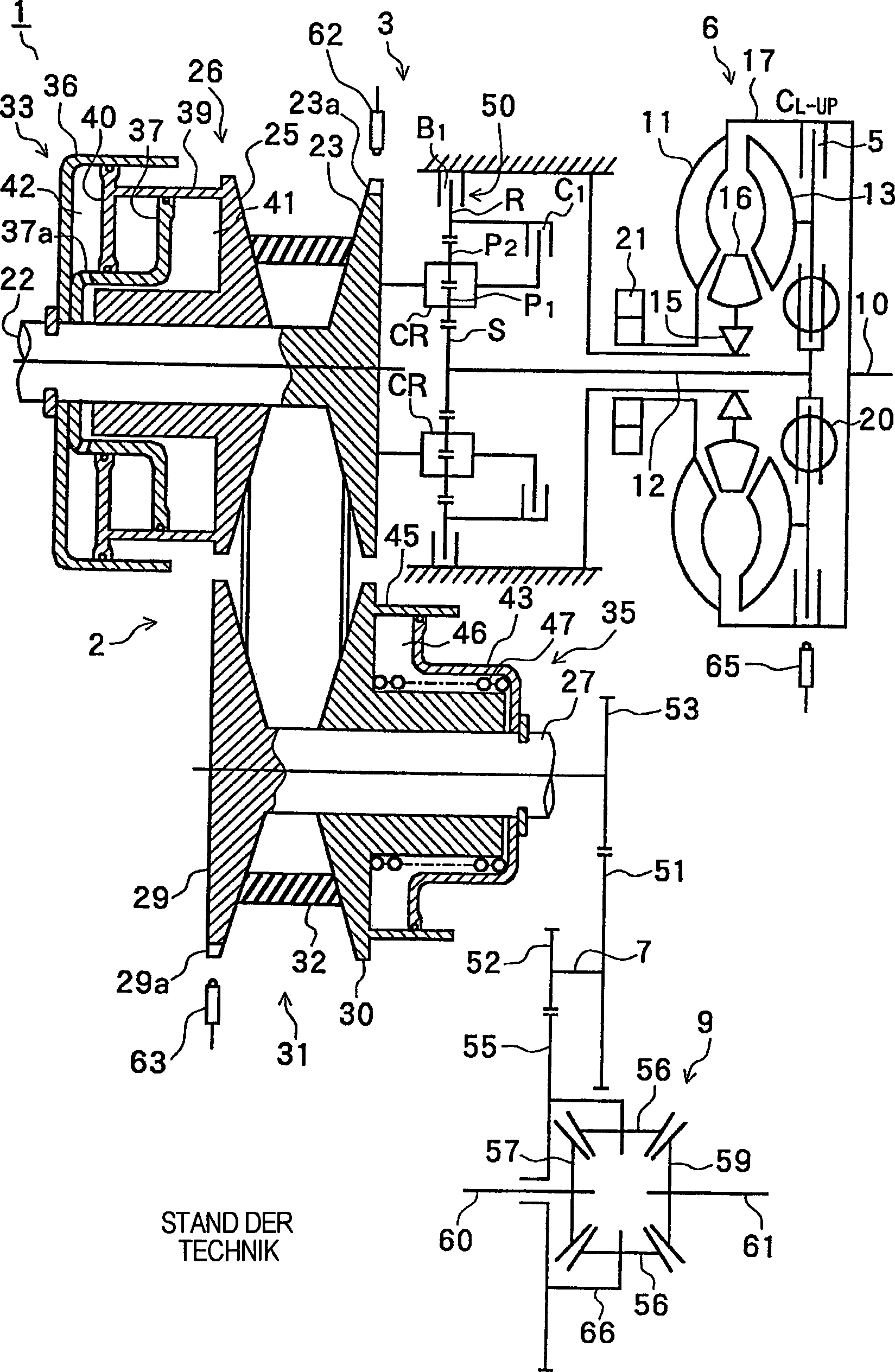
1 ist
ein schematisches Diagramm eines kontinuierlich variablen Getriebes
gemäß dem Stand der
Technik. 1 FIG. 12 is a schematic diagram of a prior art continuously variable transmission. FIG.
2 ist
eine Figur, die einen Hydraulikkreis gemäß dem Stand der Technik zeigt,
der eine Basis der Erfindung darstellt. 2 Fig. 10 is a figure showing a prior art hydraulic circuit which is a basis of the invention.
3 ist
eine Vergrößerung eines
Abschnitts aus 2 zur Erläuterung der Verstärkung eines
Leitungsdrucks. 3 is an enlargement of a section 2 to explain the amplification of a line pressure.
4 ist
eine Fig., die einen Hydraulikkreis der Erfindung zeigt. 4 is a Fig., Which shows a hydraulic circuit of the invention.
5 ist
eine Vergrößerung eines
Abschnitts aus 4, die die Verstärkungsfaktoränderungsvorrichtung
eines ersten Ausführungsbeispiels zeigt. 5 is an enlargement of a section 4 showing the gain adjusting apparatus of a first embodiment.
6 ist
eine abgewandelte Vergrößerung eines
Abschnitts aus 4, die eine Verstärkungsfaktoränderungsvorrichtung
eines zweiten Ausführungsbeispiels
zeigt. 6 is a modified enlargement of a section 4 showing a gain changing apparatus of a second embodiment.
7 ist
eine Figur, die das Verhältnis
zwischen einem ersten Signaldruck und einem Leitungsdruck in dem
ersten Ausführungsbeispiel
zeigt. 7 Fig. 12 is a figure showing the relationship between a first signal pressure and a line pressure in the first embodiment.
8 ist
eine Figur, die das Verhältnis
zwischen einem ersten Signaldruck und einem Leitungsdruck in dem
zweiten Ausführungsbeispiel
zeigt. 8th Fig. 12 is a figure showing the relationship between a first signal pressure and a line pressure in the second embodiment.
9 ist
eine Figur, die den Hydraulikkreis in dem ersten Ausführungsbeispiel
zeigt, der einen Einstellmechanismus hat. 9 Fig. 12 is a figure showing the hydraulic circuit in the first embodiment having an adjusting mechanism.
10 ist
eine Figur, die ein Verhältnis
zwischen einem Stromwert und einem Regeldruck in dem ersten Ausführungsbeispiel
zeigt. 10 FIG. 12 is a figure showing a relationship between a current value and a control pressure in the first embodiment. FIG.
11 ist
eine Figur, die den Hydraulikkreis in dem zweiten Ausführungsbeispiel
zeigt, der einen Einstellmechanismus hat. 11 Fig. 12 is a figure showing the hydraulic circuit in the second embodiment having an adjustment mechanism.
12 ist
eine Figur, die ein Verhältnis
zwischen einem Stromwert und einem Regeldruck aus dem Stand der
Technik zeigt. 12 FIG. 13 is a figure showing a relationship between a current value and a control pressure of the prior art.
Die
Erfindung wird anhand einer detaillierten Beschreibung von bevorzugten
Ausführungsbeispielen
unter Bezugnahme auf die beigefügten
Zeichnungen viel verständlicher.The
The invention will be apparent from a detailed description of preferred
embodiments
with reference to the attached
Drawings much more understandable.
In
dieser Beschreibung werden Wörter
wie ober, unter, oben oder unten durchgehend in Förder- bzw.
Transportrichtungen verwendet. Diese Worte sind auf die Figuren
bezogen und stellen keine absolute Richtung dar. Begriffe wie erste
Richtung, entgegengesetzte Richtung und zweite Richtung könnten auch
verwendet werden, aber sie würden
den Zusatz von Pfeilen zu den Figuren sowie zusätzliche Erläuterungen benötigen. Somit
werden zur Vereinfachung Wörter
bezüglich
der visuellen Darstellung verwendet und sollen nicht einschränkend gemeint sein.In
this description becomes words
as above, below, above or below continuously in conveyor or
Transport directions used. These words are on the figures
and do not represent an absolute direction. Terms like first
Direction, opposite direction and second direction could also
be used, but they would
the addition of arrows to the figures and additional explanations need. Consequently
become words for simplicity
in terms of
The visual representation used and is not meant to be limiting.
Das
erste Ausführungsbeispiel
der Erfindung wird in der folgenden Reihenfolge beschrieben:
- (1) Eine Konstruktion eines kontinuierlich
variablen Getriebes, das von einem hydraulischen Steuersystem für ein Automatikgetriebe
versorgt wird.
- (2) Eine Konstruktion eines Hydraulikkreises, der eine Basis
der Erfindung bildet.
- (3) Funktionen des kontinuierlich variablen Getriebes und des
hydraulischen Kreises.
- (4) Regeln eines Leitungsdrucks PL.
- (5) Eine Konstruktion des Hydraulikregelsystems für ein Automatikgetriebe.
- (6) Eine Funktion des hydraulischen Regelsystems.
- (7) Das Einstellen von Ventilen in dem hydraulischen Regelsystem.
The first embodiment of the invention is described in the following order: - (1) A construction of a continuously variable transmission supplied by a hydraulic control system for an automatic transmission.
- (2) A construction of a hydraulic circuit forming a basis of the invention.
- (3) Functions of the continuously variable transmission and the hydraulic circuit.
- (4) Regulating line pressure PL.
- (5) A construction of the hydraulic control system for an automatic transmission.
- (6) A function of the hydraulic control system.
- (7) Adjusting valves in the hydraulic control system.
Die
Konstruktion eines kontinuierlich variablen Getriebes, das mit einem
hydraulischen Regelsystem für
ein Automatikgetriebe der Erfindung versorgt wird, wird unter Bezugnahme
auf 1 beschrieben. Die Fig. zeigt den Umriß eines
Aufbaus eines kontinuierlich variablen Getriebes für ein Fahrzeug,
das mit einem hydraulischen Regelsystem für ein Automatikgetriebe versorgt
wird.The construction of a continuously variable transmission provided with a hydraulic control system for an automatic transmission of the invention will be described with reference to FIG 1 described. The figure shows the outline of a structure of a continuously variable transmission for a vehicle, which is supplied with a hydraulic control system for an automatic transmission.
Wie
in 1 gezeigt ist, weist das kontinuierlich variable
Getriebe 1 einen CVT 2 (der ein kontinuierlicher
variabler Getriebemechanismus der Riemenbauart ist), eine Vorwärts-/Rückwärts-Modusauswahlvorrichtung 3,
einen Drehmomentwandler 6, der mit einer Sperrkupplung 5 ausgestattet
ist, eine Zählerwelle 7 und
eine Differentialvorrichtung 9 auf. Diese Vorrichtungen
werden durch ein geteiltes Gehäuse
abgedeckt.As in 1 is shown has the continuously variable transmission 1 a CVT 2 (which is a belt-type continuous variable transmission mechanism), a forward / reverse mode selector 3 , a torque converter 6 that with a lockup clutch 5 equipped, a counter shaft 7 and a differential device 9 on. These devices are covered by a split housing.
Der
Drehmomentwandler 6 weist ein Pumpenflügelrad 11 auf, das über eine
Frontabdeckung 17 mit einer Motorausgangswelle 10 verbunden
ist, einen Turbinenläufer 13,
der über
eine Einwegkupplung 15 mit einer Eingangswelle 12 verbunden
ist, und einen Stator 16, der auf dem Getriebegehäuse abgestützt wird.
Eine Sperrkupplung 5 wird zwischen der Eingangswelle 12 und
der Frontabdeckung 17 dazwischengelegt. Eine Dämpferfeder 20 ist
zwischen der Sperrkupplungsplatte und der Eingangswelle 12 eingelegt.
Eine Ölpumpe 21 ist
an dem Pumpenflügelrad 11 verbunden
und wird durch dieses angetrieben.The torque converter 6 has a pump impeller 11 on top of that via a front cover 17 with an engine output shaft 10 connected, a turbine runner 13 that has a one-way clutch 15 with an input shaft 12 connected, and a stator 16 , which is supported on the gear housing. A lockup clutch 5 is between the input shaft 12 and the front cover 17 interposed. A damper spring 20 is between the lockup plate and the input shaft 12 inserted. An oil pump 21 is on the pump impeller 11 connected and is driven by this.
Der
CVT 2 weist eine Primärriemenscheibe 26,
eine Sekundärriemenscheibe 31 und
einen Metallriemen 32 auf, der um die Riemenscheiben 26, 31 herumgewickelt
ist. Die Primärriemenscheibe 26 weist
eine fixierte Antriebsscheibe 23 auf, die an einer Primärwelle 22 befestigt
ist, und eine bewegliche Antriebsscheibe 25, die auf der
Primärwelle 22 axial gleitfähig gelagert
ist. Die Sekundärriemenscheibe 31 weist
eine befestigte Antriebsscheibe 29 auf, die an einer Sekundärwelle 27 befestigt
ist, und eine bewegliche Antriebsscheibe 30, die auf der
Sekundärwelle 27 axial
gleitfähig
abgestützt
wird.The CVT 2 has a primary pulley 26 , a secondary pulley 31 and a metal strap 32 on, around the pulleys 26 . 31 is wrapped around. The primary pulley 26 has a fixed drive pulley 23 on that at a primary wave 22 is attached, and a movable drive pulley 25 that are on the primary wave 22 is axially slidably mounted. The secondary pulley 31 has a fixed drive pulley 29 on that at a secondary shaft 27 is attached, and a movable drive pulley 30 on the secondary shaft 27 is axially slidably supported.
Eine
hydraulische Betätigungsvorrichtung 33,
die einen Doppelkolben aufweist, ist hinter der beweglichen Antriebsscheibe 25 auf
der Primärseite angeordnet.
Eine hydraulische Betätigungsvorrichtung 35,
die einen einzigen Kolben aufweist, ist hinter der beweglichen Antriebsscheibe 30 auf
der Sekundärseite
angeordnet. Die hydraulische Betätigungsvorrichtung 33 auf
der Primärseite
weist ein Zylinderbauteil 36 und ein Reaktionsstützbauteil 37 auf,
das an der Primärwelle 22 befestigt
ist und ein Kolbenbauteil 40 und ein zylindrisches Bauteil 39,
das an der beweglichen Antriebsscheibe 25 fixiert wird.
Eine erste Hydraulikkammer 41 wird von dem zylindrischen
Bauteil 39, dem Reaktionsstützbauteil 37, der Primärwelle 22 und
der Rückseite
der beweglichen Antriebsscheibe 25 gebildet. Eine zweite
hydraulische Kammer 42 wird von dem Zylinderbauteil 36, dem
Kolbenbauteil 40 und dem Reaktionsstützbauteil 37 gebildet.
Die erste Hydraulikkammer 41 und die zweite Hydraulikkammer 42 sind über ein
Durchgangsloch 37a durchgängig gemacht. Als ein Ergebnis
der Kombination der gleichen hydraulischen Drücke in den Hydraulikkammern 41, 42 wird
eine Kraft in der Axialrichtung erzeugt, die grob das Doppelte als
jene einer sekundärseitenhydraulik-Betätigungsvorrichtung 35 beträgt. Die
Sekundärseitenhydraulik-Betätigungsvorrichtung 35 weist
ein Reaktionsstützbauteil 43 auf,
das an der Sekundärwelle 27 befestigt
ist, und ein zylindrisches Bauteil 45, das an der Rückseite
der beweglichen Antriebsscheibe 30 befestigt wird. Eine
einzige Hydraulikkammer 46 wird durch diese Bauteile und
die Sekundärwelle 27 gebildet.
Eine unter Vorspannung stehende Feder 47 wird zwischen
der beweglichen Antriebsscheibe 30 und dem Reaktionsstützbauteil 43 angeordnet
und zusammengedrückt.A hydraulic actuator 33 , which has a double piston, is behind the movable drive pulley 25 arranged on the primary side. A hydraulic actuator 35 , which has a single piston, is behind the movable drive pulley 30 arranged on the secondary side. The hydraulic actuator 33 on the primary side has a cylinder component 36 and a reaction support member 37 on, that at the primary shaft 22 is attached and a piston component 40 and a cylindrical member 39 attached to the movable drive pulley 25 is fixed. A first hydraulic chamber 41 is from the cylindrical component 39 , the reaction support component 37 , the primary wave 22 and the back of the movable drive pulley 25 educated. A second hydraulic chamber 42 is from the cylinder component 36 , the piston component 40 and the reaction support member 37 educated. The first hydraulic chamber 41 and the second hydraulic chamber 42 are over a through hole 37a made consistently. As a result of the combination of the same hydraulic pressures in the hydraulic chambers 41 . 42 a force is generated in the axial direction that is roughly twice that of a secondary side hydraulic actuator 35 is. The secondary side hydraulic actuator 35 has a reaction support component 43 on, that at the secondary shaft 27 is attached, and a cylindrical member 45 at the rear of the movable drive pulley 30 is attached. A single hydraulic chamber 46 is through these components and the secondary shaft 27 educated. A prestressed spring 47 is between the movable drive pulley 30 and the reaction support member 43 arranged and compressed.
Die
Vorwärts-/Rückwärtsmodusauswahlvorrichtung 3 weist
ein Doppelritzelplanetengetriebe 50, eine Umkehrbremse
B1 und eine Direktkupplung C1 auf. In dem Doppelritzelgetriebe 50 ist
ein Sonnenrad S mit der Eingangswelle 12 verbunden, ein
Träger CR,
der ein erstes Ritzel P1 und ein zweites Ritzel P2 trägt, ist
mit einer primärseitig
befestigen Antriebsscheibe 23 verbunden, ein Ringzahnrad
R ist mit der Umkehrbremse B1 verbunden und die Direktkupplung C1
ist zwischen dem Träger
CR und dem Ringzahnrad R angeordnet.The forward / reverse mode selector 3 has a double pinion planetary gear 50 , a reverse brake B1 and a direct clutch C1. In the double pinion gear 50 is a sun gear S with the input shaft 12 connected, a carrier CR, which carries a first pinion P1 and a second pinion P2, is secured to a primary side fixed drive pulley 23 a ring gear R is connected to the reverse brake B1 and the direct clutch C1 is disposed between the carrier CR and the ring gear R.
Ein
großes
Zahnrad 51 und ein kleines Zahnrad 52 sind an
der Gegenwelle 7 befestigt. Das große Zahnrad 51 wälzt mit
einem Zahnrad 53, das an der zweiten Welle 27 befestigt
ist. Das kleine Zahnrad wälzt
mit einem Zahnrad 55 der Differentialvorrichtung 9.
In der Differentialvorrichtung 9 wird die Drehung von einem
Differentialgetriebe 56, das durch ein Differentialgehäuse 66 abgestützt ist,
das das Zahnrad 55 enthält, über linke
und rechte Seitenzahnräder 57, 59 an
die linken und rechten Achsen 60, 61 übertragen.A big gear 51 and a small gear 52 are at the countershaft 7 attached. The big gear 51 rolls with a gear 53 that at the second wave 27 is attached. The small gearwheel rolls with a gear 55 the differential device 9 , In the differential device 9 is the rotation of a differential gear 56 that through a differential case 66 supported, that is the gear 55 contains, via left and right side gears 57 . 59 to the left and right axles 60 . 61 transfer.
Eine
Vielzahl unregelmäßiger Abschnitte 23a sind
mit einem gleichen Zwischenraum auf dem Außenabschnitt der primärseitig
befestigten Antriebssscheibe 23 durch Verzahnen ausgebildet.
Ein elektromagnetischer Aufnehmer 62 ist an einer Position
befestigt, die den unregelmäßigen Abschnitten 23a eines
Gehäuses
gegenüberliegt.
Desweiteren sind viele unregelmäßige Abschnitte 29a mit
einem gleichen Zwischenraum auf dem Außenabschnitt der sekundärseitig
befestigten Antriebsscheibe 29 durch Verzahnen ausgebildet.
Ein elektromagnetischer Aufnehmer 63 ist an einer Position
befestigt, die den unregelmäßigen Abschnitten 29a des
Gehäuses
gegenüberliegt.
Die elektromagnetischen Aufnehmer 62, 63 sind
so angeordnet, daß sich
die Erfassungsoberflächen
der elektromagnetischen Aufnehmer 62, 63 nahe
an den unregelmäßigen Abschnitten 23a, 29a befinden.
Der elektromagnetische Aufnehmer 62 bildet einen primären (Eingangs-)Drehzahlsensor
zur Erfassung der unregelmäßigen Abschnitte 23a.
Der elektromagnetische Aufnehmer 63 bildet einen sekundären (Ausgangs-)Drehzahlsensor
(Fahrzeuggeschwindigkeitssensor) zur Erfassung der unregelmäßigen Abschnitte 29a.
Eine elektromagnetischer Aufnehmer 65 ist nahe an der vorderen
Abdeckung 17 angeordnet. Der elektromagnetische Aufnehmer 65 bildet
einen Motordrehzahlsensor.A variety of irregular sections 23a are with an equal gap on the outer portion of the primary side mounted drive pulley 23 formed by gearing. An electromagnetic transducer 62 is attached to a position corresponding to the irregular sections 23a a housing opposite. Furthermore, there are many irregular sections 29a with an equal gap on the outer portion of the secondary side fixed drive pulley 29 formed by gearing. An electromagnetic transducer 63 is attached to a position corresponding to the irregular sections 29a the housing is opposite. The electromagnetic pickup 62 . 63 are arranged so that the detection surfaces of the electromagnetic pickup 62 . 63 close to the irregular sections 23a . 29a are located. The electromagnetic transducer 62 forms a primary (input) speed sensor for detecting the irregular sections 23a , The electromagnetic transducer 63 forms a secondary (output) speed sensor (vehicle speed sensor) for detecting the irregular sections 29a , An electromagnetic transducer 65 is close to the front cover 17 arranged. The electromagnetic transducer 65 forms an engine speed sensor.
Ein
Eingangsdrehmoment wird wie folgt berechnet. Ein Motordrehmoment
wird aus einer Tabelle erhalten, die auf einer Drosselöffnung und
einer Motordrehzahl basiert. Solche Tabellen sind aus dem Stand
der Technik bekannt. Ein Drehzahlverhältnis wird berechnet, basierend
auf einer Eingangsdrehzahl und einer Ausgangsdrehzahl des Drehmomentwandlers 6.
Ein Drehmomentverhältnis
wird aus einer auf dem Drehzahlverhältnis basierenden Tabelle erhalten.
Solche Tabellen sind aus dem Stand der Technik bekannt. Das Eingangsdrehmoment
wird durch Multiplizieren des Drehmomentverhältnisses und des Motordrehmoments
berechnet.An input torque is calculated as follows. Engine torque is obtained from a table based on throttle opening and engine speed. Such tables are known in the art. A speed ratio is calculated based on an input speed and an output speed of the torque converter 6 , A torque ratio is obtained from a speed ratio based table. Such tables are known in the art. The input torque is calculated by multiplying the torque ratio and the engine torque.
Die
Konstruktion des hydraulischen Kreises des kontinuierlich variablen
Getriebes 1 wird unter Bezugnahme auf 2 beschrieben.
In der Erfindung wird, wie nachfolgend diskutiert werden wird, eine
Verstärkungsfaktoränderungsvorrichtung,
beispielsweise ein Verstärkungsregelungsventil 110 in 4,
dem Hydraulikkreis, der in 2 gezeigt
ist, zugefügt.The construction of the hydraulic circuit of the continuously variable transmission 1 is referring to 2 described. In the invention, as will be discussed below, a gain-factor changing device, such as a gain control valve, is used 110 in 4 , the hydraulic circuit used in 2 shown added.
In 2 gibt
es eine Ölpumpe 21,
ein Ölpumpenregelventil 70 und
ein Ölpumpenmagnetventil
S2 für
das Ölpumpenregelventil.
Ferner ist ein Primärregelventil 72 gezeigt,
ein Sekundärregelventil 73,
ein Linearmagentventil SLT für
einen Leitungsdruck zur Regelung des Leitungsdrucks, ein lineares Sperrmagnetventil
SLU zur Blockierregelung, ein lineares Verhältnismagnetventil SLR für eine Verhältnisregelung
und ein Modulationsventil 76 zur Regelung der Magnet- bzw.
Solenoidventile.In 2 there is an oil pump 21 , an oil pump control valve 70 and an oil pump solenoid valve S2 for the oil pump control valve. Furthermore, a primary control valve 72 shown a secondary control valve 73 a linear-gap valve SLT for a line pressure for controlling the line pressure, a linear blocking solenoid SLU for blocking control, a linear ratio solenoid valve SLR for a ratio control, and a modulating valve 76 for controlling the solenoid or solenoid valves.
Ein
manuelles Ventil 77 wird manuell betätigt, um einen modulierten
Druck, der von einem Kupplungsmodulationsventil 79 moduliert
wird, von einer Öffnung 1 zu
einer Öffnung 2 oder
einer Öffnung 3 zu
schalten, wie in der Tabelle in den 2 oder 4 gezeigt
ist. In 2 ist ferner ein C1-Regelventil 80 gezeigt,
ein Neutral-Übertragungsventil 81,
ein Umkehrverhinderungsventil 82 und ein Magnetventil S1
zur Regelung des Vorwärts-/Rückwärtsbetriebes.
Ferner ist eine hydraulische Servovorrichtung C1 für die Direktkupplung
C1 gezeigt, eine hydraulische Servovorrichtung B1 für die Umkehrbremse
B1, ein Speicher 90 für
die hydraulische Servovorrichtung B1, und ein Speicher 91 für die hydraulische Servovorrichtung
C1. Ferner ist dort ein Verhältnisregelungsventil 92,
eine hydraulische Primärseitenbetätigungsvorrichtung 33 und
eine hydraulische Sekundärseitenbetätigungsvorrichtung 35 gezeigt.
Es ist auch ein Sperregelungsventil 95, ein Sperrübertragungsventil 96 und
ein Magnetventil S3 zur Änderung
des Sperrzustandes gezeigt. In 2 zeigt
EX eine Drainageöffnung.
Ferner ist ein Bypassregelungsventil 97, ein Sekundär-Regeldruckmodulationsventil 99 und
ein Kühler 100 gezeigt.A manual valve 77 is manually operated to a modulated pressure, by a clutch modulation valve 79 is modulated by an opening 1 to an opening 2 or an opening 3 to switch, as in the table in the 2 or 4 is shown. In 2 is also a C1 control valve 80 shown a neutral transfer valve 81 , a reversal prevention valve 82 and a solenoid valve S1 for controlling the forward / reverse operation. Further, there is shown a hydraulic servo C1 for the direct clutch C1, a hydraulic servo B1 for the reverse brake B1, a memory 90 for the hydraulic servo B1, and a memory 91 for the hydraulic servo C1. Further, there is a ratio control valve 92 , a hydraulic primary side actuator 33 and a hydraulic secondary side actuator 35 shown. It is also a damper valve 95 , a lock transfer valve 96 and a solenoid valve S3 for changing the lock state. In 2 EX shows a drainage opening. Further, a bypass control valve 97 , a secondary control pressure modulation valve 99 and a cooler 100 shown.
Die
Funktion des kontinuierlichen variablen Getriebes 1 und
des hydraulisches Kreises werden nun beschrieben. Durch den Betrieb
der Ölpumpe 21 basierend
auf der Motordrehung wird ein vorbestimmter Druck erhalten. Der
vorbestimmte Druck wird durch das Primärregelventil 72 auf
einen Leitungsdurck PL eingeregelt, basierend auf dem Leitungsdruck-Linearsolenoidventil
SLT, das durch ein Signal geregelt wird, welches von einer Regeleinheit basierend
auf dem Riemenscheibenverhältnis
und dem Eingangsdrehmoment berechnet wird. Der Leitungsdruck PL
wird durch das Sekundärregelventil 73 auf
einen Sekundärdruck
PS eingeregelt, was nachstehend erläutert werden soll. Wenn kein
hoher Leitungsdruck benötigt
wird, beispielsweise wenn ein Fahrzeug steht, wird das Pumpensolenoidventil
S2 basierend auf einem Signal von der Regeleinheit so geregelt,
daß das Ölpumpenregelventil 70 auf
eine rechte halbseitige Position bewegt wird, wie in 2 gezeigt
ist, und der vorbestimmte Druck von der Ölpumpe 21 zirkuliert
wird.The function of the continuous variable transmission 1 and the hydraulic circuit will now be described. By the operation of the oil pump 21 based on the engine rotation, a predetermined pressure is obtained. The predetermined pressure is through the primary control valve 72 is regulated to a line pressure PL based on the line pressure linear solenoid valve SLT which is controlled by a signal calculated by a control unit based on the pulley ratio and the input torque. The line pressure PL is through the secondary control valve 73 regulated to a secondary pressure PS, which will be explained below. When no high line pressure is needed, for example, when a vehicle is stationary, the pump solenoid valve S2 is controlled based on a signal from the control unit so that the oil pump control valve 70 is moved to a right half-sided position, as in 2 is shown, and the predetermined pressure from the oil pump 21 is circulated.
Wenn
sich das manuelle Ventil 77 im D(Antrieb)-Bereich oder
L(Niedrig)-Bereich befindet, wird der hydraulische Druck von der Öffnung 1 über die Öffnung 2 auf
die hydraulische Servovorrichtung C1 für die Direktkupplung C1 aufgebracht
und die Direktkupplung C1 gelangt in Eingriff. In diesem Zustand wird
die Drehung von der Motorausgangswelle 10 über den
Drehmomentwandler 6, die Eingangswelle 12 und
das Planetengetriebe 50, das als Ergebnis des Eingriffs
der Direktkupplung C1 in einem direkten Verbindungszustand steht,
auf die Primärriemenscheibe 26 übertragen.
Die Drehung wird über
das CVT2 an die sekundäre
Welle 27 übertragen,
wenn das CVT2 geeignet modifiziert wird, und sie wird anschließend über die
Gegenwelle 7 und die Differentialvorrichtung 9 auf
die linken und rechten Achsen 60, 61 übertragen.When the manual valve 77 is in the D (drive) range or L (low) range, the hydraulic pressure from the port 1 over the opening 2 is applied to the hydraulic servo C1 for the direct clutch C1 and the high clutch C1 is engaged. In this state, the rotation is from the motor output shaft 10 over the torque converter 6 , the input shaft 12 and the planetary gear 50 which is in a direct connection state as a result of the engagement of the direct clutch C1 on the primary pulley 26 transfer. The rotation is via the CVT2 to the secondary shaft 27 transferred when the CVT2 is suitably modified, and then it is over the countershaft 7 and the differential device 9 on the left and right axles 60 . 61 transfer.
Wenn
das manuelle Ventil 77 zum R-(Umkehr)-Bereich bewegt wird,
wird der hydraulische Druck von der Öffnung 1 über die Öffnung 3 zur
hydraulischen Servovorrichtung B1 für die Bremse B1 aufgebracht.
In diesem Zustand gelangt ein Ringzahnrad R des Planetengetriebes 50 in
Eingriff, während
die Drehung eines Sonnenrades S von der Eingangswelle 12 durch
den Träger
CR in eine Umkehrumdrehung umgewandelt wird, und die umgekehrte Drehung
wird an die Primärriemenscheibe 26 übertragen.If the manual valve 77 is moved to the R (reverse) region, the hydraulic pressure from the opening 1 over the opening 3 applied to the hydraulic servo B1 for the brake B1. In this state, enters a ring gear R of the planetary gear 50 engaged while the rotation of a sun gear S from the input shaft 12 is converted by the carrier CR in a reverse rotation, and the reverse rotation is to the primary pulley 26 transfer.
In
dem CVT2 wird der Leitungsdruck PL von dem Primärregelventil 72 auf
das hydraulische Betätigungsglied 35 der
sekundären
Riemenscheibe 31 aufgebracht, so daß eine Riemengreifkraft bezogen auf
das Eingangsdrehmoment und das Verschiebeverhältnis aufgebracht wird. Das
Verhältnis-Linearsolenoidventil
SLR wird für
die Verhältnisregelung
basierend auf dem Verschiebesignal von der Regeleinheit geregelt
und das Verhältnisregelventil 92 wird durch
den Signaldruck von dem Verhältnis-Linearsolenoidventil
SLR geregelt. Der geregelte Druck von der Ausgangsöffnung des
Verhältnisregelungsventils 92 wird
für die
Primärriemenscheibe 26 auf
die hydraulische Betätigungsvorrichtung 33 aufgebracht, die
den Doppelkolben aufweist. Anschließend wird das Übertragungsverhältnis des
CVT2 geeignet geregelt.In the CVT2, the line pressure PL becomes from the primary control valve 72 on the hydraulic actuator 35 the secondary pulley 31 applied, so that a belt grip force is applied based on the input torque and the shift ratio. The ratio linear solenoid valve SLR is controlled for the ratio control based on the shift signal from the control unit and the ratio control valve 92 is controlled by the signal pressure from the ratio linear solenoid valve SLR. The regulated pressure from the outlet port of the ratio control valve 92 is for the primary pulley 26 on the hydraulic actuator 33 applied, which has the double piston. Then, the transmission ratio of the CVT2 is properly controlled.
Das
Drehmoment der Motorausgangswelle 10 wird über den
Drehmomentwandler 6 auf die Eingangswelle 12 übertragen.
Besonders wenn der Antrieb eines Fahrzeugs gestartet wird, wird
das Drehmoment durch den Drehmomentwandler 6 umgewandelt,
um hoch zu sein, und wird auf die Eingangswelle 12 übertragen.
Anschließend
fährt ein
Fahrzeug gleichmäßig an.
Der Drehmomentwandler 6 weist die Sperrkupplung 5 auf.
Bei einem stabilen Hochgeschwindigkeitsfahrzustand ist die Sperrkupplung 5 in
Eingriff, dann ist die Motorausgangswelle 10 direkt mit
der Eingangswelle 12 verbunden, so daß ein Leistungsverlust basierend
auf dem Öl
in dem Drehmomentwandler reduziert wird.The torque of the motor output shaft 10 is about the torque converter 6 on the input shaft 12 transfer. Especially when driving a vehicle is started, the torque is through the torque converter 6 converted to be high, and is on the input shaft 12 transfer. Then a vehicle drives smoothly. The torque converter 6 has the lockup clutch 5 on. At a stable high-speed running condition, the lock-up clutch is 5 engaged, then the motor output shaft 10 directly to the input shaft 12 connected, so that a power loss is reduced based on the oil in the torque converter.
Die
Regelung des Leitungsdrucks PL wird unter Bezugnahme auf 3 beschrieben.
Eine Feder 72b wird in einer ersten Endkammer 1 des
Primärregelventils 72 angeordnet
und zusammengedrückt.
Ein Regeldruckausgang von der Ausgangsöffnung m des Leitungsdruck-Linearsolenoidventils SLT
wird über
eine Öffnung 101 in
die erste Endkammer 1 eingegeben. Der Leitungsdruck PL
wird über eine Öffnung 102 in
eine zweite Endkammer n des Primärregelventils 72 eingegeben.
Deshalb wird ein Spulenkörper 72a durch
den Regeldruckeingang in die erste Endkammer 1 und den
Rückkopplungsdruckeingang
in die zweite Endkammer n betätigt. Anschließend wird
ein hydraulischer Druck, der von der Ölpumpe 21 an eine Öffnung o
des Primärregelventils 72 angelegt
wird, durch Verbinden der Öffnung
o an eine Drainageöffnung
EX und eine zweite Öffnung
q mit einer vorbestimmten Rate geregelt. Anschließend wird
der Leitungsdruck PL basierend auf dem Eingangsdrehmoment berechnet
und das Übertragungsverhältnis des
CVT2 wird an einen Ölpfad
h angelegt.The control of the line pressure PL will be described with reference to FIG 3 described. A feather 72b is in a first end chamber 1 of the primary control valve 72 arranged and compressed. A control pressure output from the output port m of the line pressure linear solenoid valve SLT is via an orifice 101 in the first end chamber 1 entered. The line pressure PL is via an opening 102 in a second end chamber n of the primary control valve 72 entered. Therefore, a bobbin 72a through the control pressure input into the first end chamber 1 and the feedback pressure input to the second end chamber n is operated. Subsequently, a hydraulic pressure is applied by the oil pump 21 to an opening o of the primary control valve 72 is applied, by connecting the opening o to a drainage opening EX and a second opening q regulated at a predetermined rate. Subsequently, the line pressure PL is calculated based on the input torque, and the transmission ratio of the CVT2 is applied to an oil path h.
Eine
Feder 73b wird in einer ersten Endkammer r des Sekundärregelventils 73 angeordnet
und zusammengedrückt.
Ein Regeldruckausgang von der Ausgangsöffnung s des Sekundärregeldruckmodulationsventils 99 wird über eine Öffnung 103 in
die erste Endkammer R eingegeben. Der Sekundärdruck PS wird über eine Öffnung 105 in
eine zweite Endkammer t des Sekundärregelventils 73 eingegeben.
Deshalb wird ein Spulenkörper 73a durch
den Regeldruckeingang in die erste Endkammer R und den Rückkopplungsdruckeingang
in die zweite Endkammer t betätigt.
Anschließend
wird ein Hydraulikdruck, der von der Öffnung q des Primärregelventils 72 an eine Öffnung u
des Sekundärregelventils 73 aufgebracht
wird, durch Kommunizieren der Öffnung
u mit einer Drainagenöffnung
EX und einer Schmierölöffnung v
mit einer vorbestimmten Rate geregelt. Anschließend wird der Sekundärdruck PS
basierend auf dem Regeldruck von der Ausgangsöffnung s des Sekundärregeldruckmodulationsventils 99 auf
einen Ölpfad
p aufgebracht. Ein Schmierdruck wird von der Schmierölöffnung v
des Sekundärregelventils 73 über eine Öffnung 109 an
eine Schmiervorrichtung 107 aufgebracht.A feather 73b is in a first end chamber r of the secondary control valve 73 arranged and compressed. A control pressure output from the output port s of the secondary control pressure modulation valve 99 will have an opening 103 entered into the first end chamber R. The secondary pressure PS is via an opening 105 in a second end chamber t of the secondary control valve 73 entered. Therefore, a bobbin 73a operated by the control pressure input into the first end chamber R and the feedback pressure input into the second end chamber t. Subsequently, a hydraulic pressure from the opening q of the primary control valve 72 to an opening u of the secondary control valve 73 is regulated by communicating the opening u with a drainage port EX and a lubricating oil port v at a predetermined rate. Subsequently, the secondary pressure PS is based on the control pressure from the output port s of the secondary control pressure modulation valve 99 applied to an oil path p. A lubrication pressure is from the lubricating oil opening v of the secondary control valve 73 over an opening 109 to a lubricating device 107 applied.
Eine
Feder 99b ist in einer ersten Endkammer w des Sekundärregeldruckmodulationsventils 99 angeordnet
und zusammengedrückt.
Der Regeldruckausgang von der Ausgangsöffnung s des Sekundärregeldruckmodulationsventils 99 wird über eine Öffnung 106 an
eine zweite Endkammer x eingegeben. Das Sekundärregeldruckmodulationsventil 99 weist
die Ausgangsöffnungen,
eine Drainagenöffnung
Ex und eine Eingangsöffnung
y auf, an die der Regeldruck von dem Leitungsdruck-Linearsolenoidventil
SLT zur Regelung des Leitungsdrucks PL über eine Öffnung 104 angelegt
wird. Die Ausgangsöffnung
s ist mit der Eingangsöffnung
y und der Drainagenöffnung
EX mit einer vorbestimmten Rate verbunden. Eine V-förmige Kerbe
y' ist in der Eingangsöffnung y
ausgebildet.A feather 99b is in a first end chamber w of the secondary control pressure modulation valve 99 arranged and compressed. The control pressure output from the output port s of the secondary control pressure modulation valve 99 will have an opening 106 entered into a second end chamber x. The secondary control pressure modulation valve 99 has the output ports, a drainage port Ex and an intake port y, to which the control pressure from the line pressure linear solenoid valve SLT for regulating the line pressure PL via an orifice 104 is created. The exit port s is connected to the entrance port y and the drain port EX at a predetermined rate. A V-shaped notch y 'is formed in the entrance opening y.
Ein
Spulenkörper 99a wird
basierend auf dem Regeldruck als ein Rückkopplungsdruckeingang in
die zweite Endkammer x und einer Vorspannkraft der Feder 99b in
der ersten Endkammer w betätigt.
Wenn der Regeldruck von dem Leitungsdruck-Linearsolenoidventil SLT niedriger als
ein vorbestimmter Druck ist, bleibt der Spulenkörper 99a auf der rechten
halbseitigen Position von 5, weil
die Vorspannkraft der Feder 99b höher ist als der Rückkopplungsdruckeingang
in die zweite Endkammer x, und anschließend wird der Regeldruckeingang
von der Ausgangsöffnung
s an die Eingangsöffnung
y eingegeben. Wenn der Regeldruck von dem Leitungsdruck-Linearsolenoidventil
SLT höher
ist als der vorbestimmte Druck, wird der Spulenkörper 99a mit dem Rückkopplungsdruckeingang
an die zweite Endkammer x und der Vorspannkraft der Feder 99b in
der ersten Endkammer w betrieben. Deshalb bleibt der Regeldruck
von der Ausgangsöffnung
s auf einem eingestellten Wert zu jener Zeit, wenn der Regeldruck
von dem Leitungsdruck-Linearsolenoidventil SLT
zugenommen hat.A bobbin 99a is based on the control pressure as a feedback pressure input into the second end chamber x and a biasing force of the spring 99b w operated in the first end chamber w. When the control pressure from the line pressure linear solenoid valve SLT is lower than a predetermined pressure, the bobbin remains 99a on the right half-sided position of 5 because the biasing force of the spring 99b is higher than the feedback pressure input to the second end chamber x, and then the control pressure input from the output port s is input to the input port y. When the control pressure from the line pressure linear solenoid valve SLT is higher than the predetermined pressure, the bobbin becomes 99a with the feedback pressure input to the second end chamber x and the biasing force of the spring 99b operated in the first end chamber w. Therefore, the control pressure from the output port s remains at a set value at the time when the control pressure from the line pressure linear solenoid valve SLT has increased.
Deshalb
regelt das Leitungsdruck-Linearsolenoidventil SLT zur Regelung des
Leitungsdrucks PL einen Modulationsdruck PM basierend auf dem Regelsignal,
das von der Regeleinheit ausgegeben wird, basierend auf dem Eingangsdrehmoment
und dem Übertragungsverhältnis des
CVT2, und gibt den geregelten Druck als Regeldruck von der Ausgangsöffnung m
aus. Anschließend
gibt das Primärregelventil 72 den Leitungsdruck
PL im Verhältnis
zum Eingangsdrehmoment zwischen einem U/D(unter Antrieb)-Zustand
und einem O/D(über
Antrieb (over drive))-Zustand des CVT2 basierend auf dem Regeldruck
aus, der geregelt wird, der an die erste Endkammer 1 des
Primärregelventils 72 aufgebracht wird.Therefore, the line pressure linear solenoid valve SLT for controlling the line pressure PL controls a modulation pressure PM based on the control signal output from the control unit based on the input torque and the transmission ratio of the CVT2, and outputs the regulated pressure as the control pressure from the output port m. Then there is the primary control valve 72 the line pressure PL in relation to the input torque between a U / D (under drive) state and an O / D (over drive) state of the CVT2 based on the control pressure that is regulated to the first end chamber 1 of the primary control valve 72 is applied.
Wenn
der Regeldruck von dem Leitungsdruck-Linearsolenoidventil SLT niedriger als
der vorbestimmte Druck ist, gibt das Sekundärregeldruckmodulationsventil 99 den
Regeldruck von der Ausgangsöffnung
s aus, der nicht geregelt ist. Dann gibt das Sekundärregelventil 73 den
Sekundärdruck
PS im Verhältnis
zum Eingangsdrehmoment zwischen dem U/D(niedriger Antrieb (under
drive))-Zustand und dem O/D(übermäßiger Antrieb
(over drive))-Zustand des CVT2 basierend auf dem Regeldruck, der nicht
geregelt ist, der von der ersten Endkammer r des Sekundärregelventils 73 aufgebracht
wird, aus. Der Sekundärdruck
PS in dem O/D-Zustand
wird auf einen benötigten
Druck festgesetzt, der für
den Drehmomentwandler 6 benötigt wird. Deshalb ist der
Sekundärdruck
PS beim U/D-Zustand ausreichend.When the control pressure from the line pressure linear solenoid valve SLT is lower than the predetermined pressure, the secondary control pressure modulation valve outputs 99 the control pressure from the output port s out, which is not regulated. Then there is the secondary control valve 73 the secondary pressure PS in relation to the input torque between the U / D (under drive) state and the O / D (over drive) state of the CVT2 based on the control pressure which is not regulated from the first end chamber r of the secondary control valve 73 is applied, off. The secondary pressure PS in the O / D state is set to a required pressure for the torque converter 6 is needed. Therefore, the secondary pressure PS in the U / D state is sufficient.
Der
Steuerdruck von den Ausgangsöffnungen
des Sekundärregeldruckmodulationsventils 99 wird
auf dem eingeregelten Wert gehalten, wenn der Regeldruck von dem
Leitungsdruck-Linearsolenoidventil SLT höher ist als der vorbestimmte
Druck. Deshalb nimmt der Leitungsdruck PL im Verhältnis zu dem
Regeldruck von dem Leitungsdruck-Linearsolenoidventil
SLT zu, aber der Sekundärdruck
PS ist auf den eingeregelten Wert basierend auf den eingeregelten
Regeldruck von der Ausgangsöffnung
s begrenzt. Die obere Begrenzung des Sekundärdrucks PS ist niedriger als
ein Grenzwert des Drehmomentwandlers 6 und ist annähernd gleich
einem höchsten benötigten Druck.
Der Grenzdruck ist ein Minimaldruck, bei dem der Drehmomentwandler 6 funktionsunfähig wird.
Der benötigte
höchste
Druck ist ein Maximaldruck bezogen auf das maximale Eingangsdrehmoment.The control pressure from the output ports of the secondary control pressure modulation valve 99 is maintained at the regulated value when the control pressure from the line pressure linear solenoid valve SLT is higher than the predetermined pressure. Therefore, the line pressure PL increases in proportion to the control pressure from the line-pressure linear solenoid valve SLT, but the secondary pressure PS is limited to the adjusted value based on the adjusted control pressure from the output port s. The upper limit of the secondary pressure PS is lower than a limit value of the torque converter 6 and is approximately equal to a highest required pressure. The limit pressure is a minimum pressure at which the torque converter 6 becomes inoperative. The required highest pressure is a maximum pressure related to the maximum input torque.
Das
hydraulische Regelsystem für
ein Automatikgetriebe weist eine Signaldruckausgabevorrichtung auf,
eine Verstärkungsfaktoränderungsvorrichtung
und eine Regelvorrichtung, und ruft Änderungen zwischen einer niedrigen
Verstärkung
und einer hohen Verstärkung
hervor. Wie in den 4 und 5 gezeigt
ist, ist die Verstärkungsfaktoränderungsvorrichtung
zwischen dem Leitungsdruck-Linearsolenoidventil SLT als die Signaldruckausgabevorrichtung, und
dem Primärregelventil 72 als
der Regelvorrichtung, positioniert, im Vergleich zu dem Hydraulikkreis,
wie in den 2 und 3 gezeigt
ist. In 4 haben die Elemente, die denselben
Aufbau und die gleichen Funktionen wie die Elemente in 2 haben,
die gleichen Bezugszahlen und -Buchstaben, wie in 2 gezeigt
ist. Einige Elemente, die sich nicht auf die Erfindung von 4 beziehen,
entsprechen nicht den Elementen in 2. Beispielsweise
ist das Sperregelventil 95 von 2 in 4 weggelassen.The hydraulic control system for an automatic transmission includes a signal pressure output device, a gain changing device and a control device, and causes changes between a low gain and a high gain. As in the 4 and 5 11, the gain changing device is shown between the line pressure linear solenoid valve SLT as the signal pressure output device, and the primary control valve 72 As the control device, positioned, compared to the hydraulic circuit, as in the 2 and 3 is shown. In 4 have the elements that have the same structure and the same functions as the elements in 2 have the same reference numbers and letters as in 2 is shown. Some elements that are not based on the invention of 4 refer, do not correspond to the elements in 2 , For example, the Sperregelventil 95 from 2 in 4 omitted.
Das
Leitungsdruck-Linearsolenoidventil SLT als die Signaldruckausgabevorrichtung
ist das gleiche Ventil, das unter Bezugnahme auf die 2 und 3 erwähnt wurde.
Das heißt,
das Leitungsdruck-Linearsolenoidventil SLT regelt den Modulationsdruck
PM von dem Solenoidmodulationsventil 79, basierend auf
dem Regelsignal, das auf dem Eingangsdrehmoment und dem Verschiebeverhältnis von
dem CVT2 basiert, von der Regeleinheit und gibt den geregelten Druck
als einen ersten Signaldruck P10 von der Ausgangsöffnung m
aus.The line pressure linear solenoid valve SLT as the signal pressure output device is the same as that described with reference to FIGS 2 and 3 was mentioned. That is, the line pressure linear solenoid valve SLT regulates the modulation pressure PM from the solenoid modulation valve 79 based on the control signal based on the input torque and the shift ratio of the CVT2, from the control unit and outputs the regulated pressure as a first signal pressure P10 from the output port m.
In
den 4 und 5, die das erste Ausführungsbeispiel
zeigen, weist die Verstärkungsfaktoränderungsvorrichtung ein
Verstärkungsregelungsventil 110 und
ein Absperrkugelventil 111 als eine Auswahlvorrichtung
auf. Wie in 5 gezeigt ist, weist das Verstärkungsregelungsventil 110 eine
Hydraulikkammer a, an die der erste Signaldruck P10-Ausgang von
dem Leitungsdruck-Linearsolenoidventil SLT eingegeben wird, eine
Eingangsöffnung c,
an die der Leitungsdruck PL-Ausgang von dem Primärregelventil 72 eingegeben
wird, und eine Ausgangsöffnung
b, von der ein Verstärkungsdruck
PG, der vom Leitungsdruck PL auf der Basis des ersten Signaldrucks
P10 geregelt wird, ausgegeben wird. Das Verstärkungsregelungsventil 110 weist
ferner einen Spulenkörper 110a auf,
der Stege L1, L2 aufweist. Der Spulenkörper 110a wird durch
eine Feder 110b nach oben vorgespannt.In the 4 and 5 10, which show the first embodiment, the gain changing device has a gain control valve 110 and a shut-off ball valve 111 as a selector. As in 5 is shown has the gain control valve 110 a hydraulic chamber a to which the first signal pressure P10 output from the line pressure linear solenoid valve SLT is input, an input port c to which the line pressure PL output from the primary regulator valve 72 is input, and an output port b from which a boost pressure PG, which is controlled by the line pressure PL on the basis of the first signal pressure P10. The gain control valve 110 also has a bobbin 110a on, the webs L1, L2 has. The bobbin 110a is by a spring 110b biased upward.
Das
Absperrkugelventil 111 weist zwei Eingänge 111a, 111b und
einen Ausgang 111c auf. Der Eingang 111a wird
mit dem Eingang des ersten Signaldrucks P10 von dem Leitungsdruck-Linearsolenoidventil
SLT versorgt. Der Eingang 111b wird mit dem Eingang des
Verstärkungsdrucks
PG von dem Verstärkungsregelungsventil 110 versorgt.
Der höhere Druck
wird von dem ersten Signaldruck P10 und dem Verstärkungsdruck
PG durch eine Kugel 111d ausgewählt. Anschließend wird
der ausgewählte
Druck als ein zweiter Signaldruck P20 von dem Ausgang 111c ausgegeben.
Der zweite Signaldruck P20 wird über die Öffnung 101 an
die erste Endkammer 1 des Primärregelventils 72 eingegeben.
Der Leitungsdruck PL als ein Ausgangsdruck wird basierend auf dem zweiten
Signaldruckeingang an die erste Endkammer 1 geregelt. Die
Erläuterung
des Aufbaus und der Funktion des Primärregelventils 72 als
Regelvorrichtung wird weggelassen, weil es dort keinen wesentlichen
Unterschied zu dem vorher beschriebenen Aufbau und der Funktion
gibt.The shut-off ball valve 111 has two entrances 111 . 111b and an exit 111c on. The entrance 111 is supplied with the input of the first signal pressure P10 from the line pressure linear solenoid valve SLT. The entrance 111b with the input of the boost pressure PG from the boost control valve 110 provided. The higher pressure is generated by the first signal pressure P10 and the boosting pressure PG by a ball 111d selected. Subsequently, the selected pressure as a second signal pressure P20 from the output 111c output. The second signal pressure P20 is via the opening 101 to the first end chamber 1 of the primary control valve 72 entered. The line pressure PL as an output pressure becomes based on the second signal pressure input to the first end chamber 1 regulated. The explanation of the structure and function of the primary control valve 72 as a control device is omitted, because there is no significant difference to the previously described structure and function.
Die
Funktion des hydraulischen Regelsystems für ein Automatikgetriebe wird
unter Bezugnahme auf die 5 und 7 beschrieben.
Wenn die Ölpumpe 21 betrieben
wird, wird der hydraulische Druck PL von der Ölpumpe 21 an die Eingangsöffnung o
des Primärregelventils 72 aufgebracht
und über
die Öffnung 102 auf
die zweite Endkammer n aufgebracht, die eine obere Seite des Spulenkörpers 72a ist,
wie in den Fig. gezeigt ist. Der Spulenkörper 72a wird durch
den hydraulischen Druckeingang an die zweite Endkammer n zu der
Feder 72b heruntergestoßen und der Spulenkörper 72a wird
in der Position der linken Hälfte
gehalten, wie in 5 gezeigt ist. Der Spulenkörper 110a des
Verstärkungsregelungsventils 110 wird
durch die Feder 110b nach oben gestoßen, und der Spulenkörper 110a wird
in der Position der linken Hälfte
in 5 gehalten. Deshalb ist die Eingangsöffnung c
des Verstärkungsregelungsventils 110 durch
den Steg L2 geschlossen und der Leitungsdruck PL wird nicht in das
Verstärkungsregelungsventil 110 eingegeben.
Der Zustand mit einer Position min ist in 7 gezeigt.
Das Bezugszeichen (P20) auf der Vertikalachse in 7 zeigt,
daß der
zweite Signaldruck P20 in Bezug zu der Änderung des ersten Signaldrucks
P10 verändert
wird.The function of the hydraulic control system for an automatic transmission will be described with reference to FIGS 5 and 7 described. If the oil pump 21 is operated, the hydraulic pressure PL from the oil pump 21 to the inlet opening o of the primary control valve 72 applied and over the opening 102 applied to the second end chamber n, which is an upper side of the bobbin 72a is as shown in the figures. The bobbin 72a becomes the spring through the hydraulic pressure input to the second end chamber n 72b pushed down and the bobbin 72a is held in the position of the left half as in 5 is shown. The bobbin 110a of the gain control valve 110 is by the spring 110b pushed up, and the bobbin 110a will be in the position of the left half in 5 held. Therefore, the input port c of the boost control valve 110 closed by the web L2 and the line pressure PL is not in the gain control valve 110 entered. The state with a position min is in 7 shown. The reference numeral (P20) on the vertical axis in 7 shows that the second signal pressure P20 is changed with respect to the change of the first signal pressure P10.
In
dem Zustand, wenn das Leitungsdruck-Linearsolenoidventil SLT den
ersten Signaldruck P10 ausgibt, wird der erste Signaldruck P10 in
die Hydraulikkammer a des Verstärkungsregelungsventils 110 eingegeben
und der erste Signaldruck P10 wird in den Eingang 111a des
Absperrkugelventils 111 eingegeben. Zu jener Zeit wird
der Verstärkungsdruck PG,
der von dem Leitungsdruck PL geregelt wird, nicht an den entgegengesetzten
Eingang 111b des Absperrkugelventils 111 eingegeben.
Deshalb wird die Kugel 111d durch den ersten Signaldruck
P10, der in den Eingang 111a eingegeben wird, nach links in 5 gestoßen. Als
ein Ergebnis wird der erste Signaldruck P10 als zweiter Signaldruck
P20 von dem Ausgang 111c des Absperrventils 111 ausgegeben. Als
ein Ergebnis wird der zweite Signaldruck P20 (laufend gleich dem
ersten Signaldruck P10) über
die Öffnung 101 in
die erste Endkammer 1 des Primärregelventils 72 eingegeben.In the state where the line pressure linear solenoid valve SLT outputs the first signal pressure P10, the first signal pressure P10 becomes the hydraulic chamber a of the boost control valve 110 entered and the first signal pressure P10 is in the input 111 the shut-off ball valve 111 entered. At that time, the boost pressure PG, which is controlled by the line pressure PL, does not become the opposite input 111b the shut-off ball valve 111 entered. That's why the bullet will 111d by the first signal pressure P10 entering the input 111 is entered, left in 5 encountered. As a result, the first signal pressure P10 becomes the second signal pressure P20 from the output 111c the shut-off valve 111 output. As a result, the second signal pressure P20 (continuously equal to the first signal pressure P10) becomes across the opening 101 in the first end chamber 1 of the primary control valve 72 entered.
Wenn
der erste Signaldruck P10 erhöht
wird, wird der Spulenkörper 110a durch
den ersten Signaldruck P10 allmählich
nach unten gestoßen
und der zweite Signaldruck P20 nimmt allmählich zu. Anschließend nimmt
auch der Leitungsdruck PL von dem Primärregelventil 72 zu.
Die Änderungsrate
des Leitungsdrucks PL bezogen auf die Änderungsrate des ersten Signaldrucks
P10, der die Verstärkung
G ist, ist als die niedrige Verstärkung G1 in 7 gezeigt.
Die niedrige Verstärkung
G1, die in 7 eine kleine Größe hat,
wird zu einem Änderungspunkt weitergeführt, der
diskutiert werden soll.When the first signal pressure P10 is increased, the bobbin becomes 110a is gradually pushed down by the first signal pressure P10, and the second signal pressure P20 gradually increases. Subsequently, the line pressure PL from the primary control valve also increases 72 to. The rate of change of the line pressure PL relative to the rate of change of the first signal pressure P10, which is the gain G, is referred to as the low gain G1 in FIG 7 shown. The low gain G1, which in 7 has a small size, is continued to a point of change to be discussed.
Wenn
sich der Spulenkörper 110a herabbewegt
hat, durch Erhöhen
des ersten Signaldrucks P10, so daß die obere Oberfläche des
Stegs L2 an dem oberen Ende der Eingangsöffnung c vorbeigeht, wird der
Leitungsdruck PL in die Eingangsöffnung
c des Verstärkungsregelungsventils 110 eingegeben und
als Verstärkungsdruck
PG von der Ausgangsöffnung
b ausgegeben. Der Verstärkungsdruck
PG wird in den Eingang 111b des Absperrkugelventils 111 eingegeben.
Zu jener Zeit stößt der Leitungsdruck
PL den Spulenkörper 110a nach
oben, weil die Druckfläche
der unteren Oberfläche
des Stegs L1 des Spulenkörpers 110a größer ist
als die Druckfläche
der oberen Oberfläche
des Stegs L2. Die Kraft, die den Spulenkörper 110a nach oben
stößt, wird
durch. Multiplizieren der Flächendifferenz
zwischen der Druckfläche
der unteren Oberfläche
des Stegs L1 und der Druckfläche
der oberen Oberfläche
des Stegs L2, die dem Verstärkungsdruck
PG unterliegen, berechnet. Der Verstärkungsdruck PG wird durch die
Kraft und den ersten Signaldruck P10, die in die Hydraulikkammer
a eingegeben werden, geregelt. Der Verstärkungsdruck PG von der Ausgangsöffnung b
wird durch Festlegen der Differenz zwischen der Druckfläche der
unteren Oberfläche
des Stegs L1 und der Druckfläche
der oberen Oberfläche
des Stegs L2 geeignet geregelt. Wenn beispielsweise die Differenz zwischen
den Druckflächen
gering ist, wird der Verstärkungsdruck
PG in Bezug zu dem vorstehend erwähnten ersten Signaldruck P10
hoch. Deshalb kann die Verstärkung
G höher
sein als die hohe Verstärkung
G2, die nachfolgend diskutiert wird.When the bobbin 110a By increasing the first signal pressure P10 so that the upper surface of the land L2 passes the upper end of the input port c, the line pressure PL becomes the input port c of the boost control valve 110 inputted and output as a boost pressure PG from the output port b. The boost pressure PG is input 111b the shut-off ball valve 111 entered. At that time, the line pressure PL hits the bobbin 110a upward, because the pressure surface of the lower surface of the web L1 of the bobbin 110a is greater than the pressure surface of the upper surface of the web L2. The force that the bobbin 110a pushes up, gets through. Multiplying the area difference between the pressure area of the lower surface of the ridge L1 and the pressure area of the upper surface of the ridge L2 subject to the boosting pressure PG. The boost pressure PG is controlled by the force and the first signal pressure P10 input to the hydraulic chamber a. The reinforcing pressure PG from the exit port b is properly controlled by setting the difference between the pressure area of the lower surface of the land L1 and the pressure area of the upper surface of the land L2. For example, when the difference between the pressure areas is small, the boosting pressure PG becomes high with respect to the above-mentioned first signal pressure P10. Therefore, the gain G may be higher than the high gain G2 discussed below.
Wenn
der erste Signaldruck P10, der in die Hydraulikkammer a eingegeben
wird, erhöht
wird, nehmen der erste Signaldruck P10, der in den Eingang 111a des
Absperrkugelventils 111 eingegeben wird, und der Verstärkungsdruck
PG, der in den Eingang 111b eingegeben wird, zu. Somit
wird der erste Signaldruck P10 als zweiter Signaldruck P20 von dem
Ausgang 111c ausgegeben, wenn der erste Signaldruck P10
niedrig ist, weil der erste Signaldruck P10 höher als der Verstärkungsdruck
PG ist und die Kugel 111d des Absperrkugelventils 111 nach
links gestoßen
wird.When the first signal pressure P10, which is input to the hydraulic chamber a, is increased, the first signal pressure P10 that is inputted increases 111 the shut-off ball valve 111 is input, and the boosting pressure PG, in the input 111b is entered, too. Thus, the first signal pressure P10 becomes the second signal pressure P20 from the output 111c output when the first signal pressure P10 is low because the first signal pressure P10 is higher than the boost pressure PG and the ball 111d the shut-off ball valve 111 is pushed to the left.
Die
Erhöhungsrate
des Verstärkungsdrucks PG,
die in den Eingang 111b eingegeben wird, ist größer als
die Erhöhungsrate
des ersten Signaldrucks P10, die in den Eingang 111a eingegeben wird.
Der Verstärkungsdruck
PG wird basierend auf dem ersten Signaldruck P10 geregelt. Die Differenz zwischen
der Druckfläche
der unteren Oberfläche des
Stegs L1 und der Druckfläche
der oberen Oberfläche
des Stegs L2 wird so festgesetzt (hergestellt), daß sie kleiner
als die Druckfläche
für den
ersten Signaldruck P10 ist.The rate of increase of the boosting pressure PG, which is in the input 111b is greater than the rate of increase of the first signal pressure P10 entering the input 111 is entered. The boost pressure PG is controlled based on the first signal pressure P10. The difference between the pressure area of the lower surface of the land L1 and the pressure area of the upper surface of the land L2 is set so as to be smaller than the pressure area for the first signal pressure P10.
Wenn
der erste Signaldruck P10 allmählich zunimmt,
wird deshalb der Verstärkungsdruck
PG an einem Punkt, der als Änderungspunkt
bezeichnet wird, der in 7 gezeigt ist, größer als
der erste Signaldruck P10. Als ein Ergebnis wird die Kugel 111d des
Absperrkugelventils 111 nach rechts gestoßen, der
Verstärkungsdruck
PG als der zweite Signaldruck P20 von dem Ausgang 111c ausgegeben
und der zweite Signaldruck P20 in das Primärregelventil 72 eingegeben.
Die Änderungsrate,
die die Verstärkung ist,
des Leitungsdrucks PL von dem Primärregelventil 72 bezogen
auf die Änderungsrate
des ersten Signaldrucks P10, die in die Hydraulikkammer a des Verstärkungsregelungsventils 110 eingegeben
wird, wird auf die hohe Verstärkung
G2 geändert,
die größer ist, als
die niedrigere Verstärkung
G1. In diesem Fall sind die Worte hoch und niedrig in der niedrigen
Verstärkung
G1 und der hohen Verstärkung
G2 relative Worte und werden nicht als hoch und niedrig im absoluten
Sinne verwendet.Therefore, when the first signal pressure P10 gradually increases, the boost pressure PG at a point called a change point in FIG 7 is shown, larger than the first signal pressure P10. As a result, the ball becomes 111d the shut-off ball valve 111 pushed to the right, the boost pressure PG as the second signal pressure P20 from the output 111c output and the second signal pressure P20 in the primary control valve 72 entered. The rate of change, which is the gain, of the line pressure PL from the primary control valve 72 with respect to the rate of change of the first signal pressure P10 entering the hydraulic chamber a of the boost control valve 110 is input is changed to the high gain G2, which is greater than the lower gain G1. In this case, the words high and low in the low gain G1 and the high gain G2 are relative words and are not used as high and low in the absolute sense.
Die
hohe Verstärkung
G2 wird solange fortgeführt,
bis der maximale Wert max des Leitungsdrucks PL entsprechend dem
Maximalwert des ersten Signaldrucks P10 erreicht ist. In 7 zeigt
die Größe des Graphen
die Verstärkung
G und die Verstärkung
G ist die niedrige Verstärkung
G1, wenn die Größe klein
ist, und die Verstärkung
G ist die hohe Verstärkung
G2, wenn die Größe groß ist.The high gain G2 is continued until the maximum value max of the line pressure PL corresponding to the maximum value of the first signal pressure P10 is reached. In 7 For example, if the size is small, the gain of G is the gain G and the gain G is the low gain G1, and the gain G is the high gain G2 when the size is large.
In
diesem Ausführungsbeispiel
wird der benötigte Änderungsbereich
des Leitungsdrucks PL, der zwischen min und max in 7 liegt,
innerhalb des Änderungsbereichs
des ersten Signaldrucks P10, der von dem Leitungsdruck-Linearsolenoidventil
SLT ausgegeben wird, erreicht.In this embodiment, the required change range of the line pressure PL, between min and max in 7 is reached within the range of change of the first signal pressure P10 output from the line pressure linear solenoid valve SLT.
In
dem kontinuierlich variablen Getriebe 1, das in 1 gezeigt
ist, sind beispielsweise die hochgenaue Steuerung für den Leitungsdruck
PL und der hohe Leitungsdruck PL, der auf dem ersten Signaldruck
P10 basiert, zu verschiedenen Zeiten oder Bedingungen erforderlich.
Die niedrige Verstärkung
G1 wird für
die hohe Genauigkeitsregelung benötigt und die hohe Verstärkung G2
wird zur Erreichung des hohen Leitungsdrucks PL benötigt. Deshalb
ist es schwierig, sowohl die hochgenaue Steuerung als auch den hohen
Leitungsdruck PL zu erreichen, wenn die Verstärkung G bei einem bestimmten Wert
wie beim Stand der Technik fixiert ist.In the continuously variable transmission 1 , this in 1 For example, the high-precision control for the line pressure PL and the high line pressure PL based on the first signal pressure P10 are required at different times or conditions. The low gain G1 is needed for the high accuracy control and the high gain G2 is needed to reach the high line pressure PL. Therefore, it is difficult to achieve both the high-precision control and the high line pressure PL when the gain G is fixed at a certain value as in the prior art.
Das
heißt,
wenn der Änderungsbereich
des ersten Signaldrucks P10 eingeregelt ist, wird in dem Fall, in
dem die Verstärkung
G als die niedrige Verstärkung
G1 zur Erzielung der hochgenauen Regelung festgesetzt ist, wie in 7 mit
der abwechselnd lang und zweimal kurz gestrichelten Linie gezeigt
ist, der benötigte
Maximalwert des Leitungsdrucks PL nicht erreicht. In dem Fall, in
dem die Verstärkung
G als die hohe Verstärkung
G2 zur Erzielung des hohen Leitungsdrucks PL festgesetzt ist, wie
in 7 mit einer abwechselnd lang und kurz gestrichelten
Linie gezeigt ist, ist die hochgenaue Regelung für den Leitungsdruck PL schwierig.That is, when the range of change of the first signal pressure P10 is adjusted, in the case where the gain G is set as the low gain G1 for achieving the high-precision control, as in FIG 7 is shown with the alternate long and two short dashed line, the required maximum value of the line pressure PL is not reached. In the case where the gain G is set as the high gain G2 for obtaining the high line pressure PL, as in FIG 7 is shown with an alternate long and short dashed line, the highly accurate control for the line pressure PL is difficult.
Basierend
auf dem Änderungspunkt
innerhalb des Änderungsbereiches
des ersten Signaldrucks P10 ist in dem Fall, in dem der erste Signaldruck
P10 niedrig ist und die hochgenaue Regelung benötigt wird, die Verstärkung als
die niedrige Verstärkung
G1 festgesetzt. Dann wird die Verstärkung G als die hohe Verstärkung G2
für den
Fall festgesetzt, bei dem der erste Signaldruck P10 hoch ist und der
hohe Leitungsdruck PL benötigt
wird. Deshalb werden sowohl die hochgenaue Regelung für den Leitungsdruck
PL als auch der hohe Leitungsdruck PL zu der geeigneten Zeit oder
unter den geeigneten Bedingungen erreicht.Based
on the change point
within the scope of change
of the first signal pressure P10 is in the case where the first signal pressure
P10 is low and the high precision control is needed, the gain as
the low gain
G1 fixed. Then, the gain G becomes the high gain G2
for the
Case where the first signal pressure P10 is high and the
high line pressure PL needed
becomes. Therefore, both the high precision control for the line pressure
PL as well as the high line pressure PL at the appropriate time or
achieved under the appropriate conditions.
Als
Weg zur Erzielung des beschriebenen Ergebnisses wählt die
Verstärkungsfaktoränderungsvorrichtung,
die das Verstärkungsregelungsventil 110 und
das Absperrkugelventil 111 aufweist, in dem ersten Ausführungsbeispiel
den zweiten Signaldruck von dem ersten Signaldruck P10 und dem Verstärkungsdruck
PG aus, der zweite Signaldruck P20 wird an das Primärregelventil 72 ausgegeben
und der Leitungsdruck PL wird basierend auf dem zweiten Signaldruck
P20 geregelt.As a way to achieve the described result, the gain-factor changing device that selects the gain control valve 110 and the shut-off ball valve 111 has, in the first embodiment, the second signal pressure from the first signal pressure P10 and the boost pressure PG, the second signal pressure P20 is applied to the primary regulator valve 72 and the line pressure PL is controlled based on the second signal pressure P20.
Ein
Einstellmechanismus und eine Einstellart werden nun beschrieben.
In dem hydraulischen Regelsystem, das in 9 gezeigt
ist, sind ein erster Einstellmechanismus 120 und ein zweiter
Einstellmechanismus 130 zu dem hydraulischen Regelsystem, das
in 5 gezeigt ist, hinzugefügt.An adjusting mechanism and a setting mode will now be described. In the hydraulic control system, which in 9 are shown are a first adjustment mechanism 120 and a second adjustment mechanism 130 to the hydraulic control system, this in 5 shown is added.
Der
erste Einstellmechanismus 120 ist auf dem unteren Endabschnitt
des Leitungsdruck-Linearsolenoidventils SLT einstückig aufgebaut
und weist einen Innengewindeabschnitt 120a auf, der auf
dem Ventilkörper
ausgebildet ist, und eine Einstellschraube 120b, die mit
dem Innengewindeabschnitt 120a in Eingriff ist. Die Feder 140b ist
zwischen der Einstellschraube 120b und dem Spulenkörper 140a angeordnet
und zusammengepreßt.
Deshalb ist die Federbelastung der Feder 140b zum Spulenkörper 140a hin
erhöht,
wenn der Schraubbetrag der Einstellschraube 120b erhöht ist,
und wird vermindert, wenn der Schraubbetrag der Einstellschraube 120b vermindert
ist.The first adjustment mechanism 120 is integrally formed on the lower end portion of the line pressure linear solenoid valve SLT and has a female threaded portion 120a on, which is formed on the valve body, and an adjusting screw 120b that with the female thread section 120a is engaged. The feather 140b is between the adjusting screw 120b and the bobbin 140a arranged and pressed together. Therefore, the spring load of the spring 140b to the bobbin 140a increases when the screwing amount of the adjusting screw 120b is increased, and is reduced when the screwing amount of the adjusting screw 120b is reduced.
Der
zweite Einstellmechanismus 130 denselben Aufbau wie der
erste Einstellmechanismus 120. Das heißt, der zweite Einstellmechanismus 130 ist auf
dem oberen Endabschnitt des Verstärkungsregelungsventils 110 einstückig aufgebaut
und weist einen Innengewindeabschnitt 130a auf, der auf
dem Ventikörper
ausgebildet ist, und eine Einstellschraube 130b, die mit
dem Innengewindeabschnitt 130a in Eingriff ist. Die Feder 110b ist
zwischen der Einstellschraube 130b und dem Spulenkörper 110a angeordnet
und zusammengedrückt.
Deshalb ist die Federlast der Feder 110b zum Spulenkörper 110a hin erhöht, wenn
der Schraubbetrag der Einstellschraube 130b erhöht ist,
und sie ist vermindert, wenn der Schraubbetrag der Einstellschraube 130b vermindert ist.The second adjustment mechanism 130 the same structure as the first adjustment mechanism 120 , That is, the second adjustment mechanism 130 is on the upper end portion of the boost control valve 110 constructed in one piece and has an internally threaded portion 130a on, which is formed on the Ventikörper, and an adjusting screw 130b that with the female thread section 130a is engaged. The feather 110b is between the adjusting screw 130b and the bobbin 110a arranged and compressed. Therefore, the spring load of the spring 110b to the bobbin 110a increases when the screwing amount of the adjusting screw 130b is increased, and it is diminished when the screwing amount of the adjusting screw 130b is reduced.
Der
Leitungsdruck PL bezogen auf einen Stromwert I, der in 10 gezeigt
ist, hat die gezeigte Streuung, die von dem Hydraulikkreis abhängt. Die Maximal-
und Minimalwerte der Streuung vor der Einstellung sind durch die
abwechselnd lang und zweimal kurz gestrichelten Linie gezeigt.The line pressure PL related to a current value I, the in 10 is shown has the dispersion shown, which depends on the hydraulic circuit. The maximum and minimum values of the dispersion before adjustment are shown by the alternate long and two short dashes line.
In
dem ersten Ausführungsbeispiel
wird der Verstärkungsdruck
PG durch den ersten Signaldruck P10 beeinflußt. Deshalb wird der Verstärkungsdruck PG
geregelt, nachdem der erste Signaldruck P10 geregelt wurde.In
the first embodiment
becomes the boost pressure
PG influenced by the first signal pressure P10. Therefore, the boost pressure PG
regulated after the first signal pressure P10 was regulated.
Zuerst
ist der Stromwert I, der auf das lineare Solenoid 140c des
Leitungsdruck-Linearsolenoidventils SLT aufgebracht wird, ein Minimalwert,
und der Leitungsdruck PL, der in Bezug zum minimalen Stromwert der
niedrigste Druck des Leitungsdrucks PL ist, wird gemessen. Wenn
der niedrigste Druck des Leitungsdrucks PL auf der Niederdruckseite
höher als
ein Einstellpunkt ist, der ein Basispunkt ist, wird der Schraubbetrag
der Einstellschraube 120b des ersten Einstellmechanismus 120 erhöht. Deshalb
nimmt die Federlast der Feder 140b zu. Als ein Ergebnis
wird der erste Signaldruck P10 vermindert und der niedrigste Druck
des Leitungsdrucks PL stimmt mit dem Einstellpunkt auf der Niederdruckseite überein.
Wenn der niedrigste Druck des Leitungsdrucks PL auf der Niederdruckseite
niedriger als der Einstellpunkt, der der Basispunkt ist, ist, wird
der Schraubbetrag der Einstellschraube 120b des ersten Einstellmechanismus 120 vermindert.
Deshalb wird die Federlast der Feder 140b vermindert. Als
ein Ergebnis wird der erste Signaldruck P10 erhöht und der niedrigste Druck
des Leitungsdrucks PL stimmt mit dem Einstellpunkt auf der Niederdruckseite überein.First, the current value I, which is on the linear solenoid 140c is applied to the line pressure linear solenoid valve SLT, a minimum value, and the line pressure PL, which is the lowest pressure of the line pressure PL with respect to the minimum current value, is measured. When the lowest pressure of the line pressure PL on the low pressure side is higher than a set point that is a base point, the screwing amount of the adjustment screw becomes 120b the first adjustment mechanism 120 elevated. Therefore, the spring load of the spring decreases 140b to. As a result, the first signal pressure P10 is decreased and the lowest pressure of the line pressure PL coincides with the set point on the low pressure side. When the lowest pressure of the line pressure PL on the low pressure side is lower than the set point that is the base point, the screwing amount of the adjusting screw becomes 120b the first adjustment mechanism 120 reduced. Therefore, the spring load of the spring 140b reduced. As a result, the first signal pressure P10 is increased and the lowest pressure of the line pressure PL coincides with the set point on the low pressure side.
Diese
Einstellung ist im wesentlichen die gleiche wie beim Stand der Technik.
Somit hat der Leitungsdruck PL wie beim Stand der Technik zu dieser
Zeit eine große
Streuung auf der Hochdruckseite.These
Adjustment is essentially the same as in the prior art.
Thus, the line pressure PL as in the prior art to this
Time a big one
Scattering on the high pressure side.
Die
Erfindung sorgt auf der Hochdruckseite für eine Einstellung, die durch
den zweiten Einstellmechanismus 130 durchgeführt werden
soll.The invention provides on the high pressure side for adjustment by the second adjustment mechanism 130 to be carried out.
Der
Verstärkungsdruck,
der den Leitungsdruck PL auf der Hochdruckseite regelt, wird geregelt.
Der Stromwert I an das lineare Solenoid 140c des Leitungsdruck-Linearsolenoidventils
SLT wird auf einen Maximalwert erhöht und der Leitungsdruck PL,
der der höchste
Druck des Leitungsdrucks PL in Bezug zum maximalen Stromwert ist,
wird gemessen. Wenn der höchste
Druck des Leitungsdrucks PL auf der Hochdruckseite höher als
ein Einstellpunkt, der ein Basispunkt ist, ist, wird der Schraubbetrag
der Einstellschraube 130b des zweiten Einstellmechanismus 130 erhöht. Deshalb
wird die Federlast der Feder 110b erhöht. Als ein Ergebnis wird der
Verstärkungsdruck
PG vermindert und der höchste
Druck des Leitungsdrucks PL stimmt mit dem Einstellpunkt auf der
Hochdruckseite überein.
Wenn der höchste Druck
des Leitungsdrucks PL auf der Hochdruckseite niedriger als der Einstellpunkt,
der der Basispunkt ist, ist, wird der Schraubbetrag der Einstellschraube 130b des zweiten
Einstellmechanismus 130 vermindert. Deshalb wird die Federlast
der Feder 110b vermindert. Als ein Ergebnis wird der Verstärkungsdruck PG
erhöht
und der höchste
Druck des Leitungsdrucks PL stimmt mit dem Einstellpunkt auf der
Hochdruckseite überein.The boost pressure regulating the line pressure PL on the high pressure side is controlled. The current value I to the linear solenoid 140c of the line pressure linear solenoid valve SLT is increased to a maximum value, and the line pressure PL, which is the highest pressure of the line pressure PL with respect to the maximum current value, is measured. When the highest pressure of the line pressure PL on the high pressure side is higher than a set point that is a base point, the screwing amount of the adjusting screw becomes 130b of the second adjustment mechanism 130 elevated. Therefore, the spring load of the spring 110b elevated. As a result, the boost pressure PG is decreased and the highest pressure of the line pressure PL coincides with the high pressure side set point. When the highest pressure of the line pressure PL on the high-pressure side is lower than the set point that is the base point, the screwing amount of the adjusting screw becomes 130b of the second adjustment mechanism 130 reduced. Therefore, the spring load of the spring 110b reduced. As a result, the boost pressure PG is increased and the highest pressure of the line pressure PL coincides with the high pressure side set point.
Die
Streuung des Leitungsdrucks PL in Bezug zum Stromwert I in jedem
Hydraulikkreis wird durch Regeln des Leitungsdrucks PL an zwei Punkten,
die der Einstellpunkt auf der Niederdruck und der Einstellpunkt
auf der Hochdruckseite sind, vermindert. Die Streuung nach den Einstellungen
ist mit einem schräg
schraffierten Linienabschnitt zwischen den abwechselnd lang und
kurz gestrichelten Linien in 10 dargestellt.
Der niedrigste Druck des Leitungsdrucks PL als der Einstellpunkt
auf der Niederdruckseite und der höchste Druck des Leitungsdrucks
PL als der Einstellpunkt auf der Hochdruckseite, beziehen sich auf
den Stromwert I mit einer hohen Genauigkeit.The dispersion of the line pressure PL with respect to the current value I in each hydraulic circuit is reduced by controlling the line pressure PL at two points which are the set point at the low pressure and the set point at the high pressure side. The scatter according to the settings is with a diagonally hatched line segment between the alternating long and short dashed lines in 10 shown. The lowest pressure of the line pressure PL as the set point on the low pressure side and the highest pressure of the line pressure PL as the set point on the high pressure side relate to the current value I with high accuracy.
Deshalb
entfällt
die Notwendigkeit, die Festigkeit und Haltbarkeit des hydraulischen
Kreises zu berücksichtigen
und den niedrigsten Regeldruck so festzusetzen, daß er hoch
ist.Therefore
deleted
the need to increase the strength and durability of the hydraulic
Circle to consider
and set the lowest control pressure to high
is.
Das
zweite Ausführungsbeispiel
wird nun beschrieben. In dem zweiten Ausführungsbeispiel ist der erste
Signaldruck P10 als zweiter Signaldruck P20 an das Primärregelventil 72 ausgegeben,
wenn der erste Signaldruck P10 niedrig ist. Wenn der erste Signaldruck
P10 hoch ist, werden sowohl der erste Signaldruck P10 also auch
der Verstärkungsdruck PG
als zweiter Signaldruck P20 an das Primärregelventil 72 ausgegeben.The second embodiment will now be described. In the second embodiment, the first signal pressure P10 as the second signal pressure P20 to the primary control valve 72 output when the first signal pressure P10 is low. When the first signal pressure P10 is high, both the first signal pressure P10 and the boost pressure PG as the second signal pressure P20 to the primary control valve 72 output.
Das
zweite Ausführungsbeispiel
ist in 6 gezeigt. Die Elemente, die denselben Aufbau
und die dieselben Funktionen haben, sind mit denselben Bezugszahlen
oder Ziffern wie das vorherige Ausführungsbeispiel bezeichnet.
Wo die Erläuterungen
dieselben sind, werden diese weggelassen, und nur die Abschnitte,
die von dem ersten Ausführungsbeispiel differieren,
werden beschrieben.The second embodiment is in 6 shown. The elements having the same structure and the same functions are denoted by the same reference numerals or numerals as the previous embodiment. Where the explanations are the same, they will be omitted, and only the portions that differ from the first embodiment will be described.
In 6 sind
das Leitungsdruck-Linearsolenoidventil SLT als die Signaldruckausgabevorrichtung
und das Verstärkungsregelungsventil
dieselben wie diejenigen in 5. Das Primärregelventil 72A, als
die Regelvorrichtung, wird an einem Ende durch Zufügen einer
Hydraulikkammer d im Vergleich zum Regelventil 72 der 5 und 9 ausgedehnt.In 6 For example, the line pressure linear solenoid valve SLT as the signal pressure output device and the boost control valve are the same as those in FIG 5 , The primary control valve 72A , as the control device, becomes at one end by adding a hydraulic chamber d in comparison to the control valve 72 of the 5 and 9 extended.
In
dem zweiten Ausführungsbeispiel
weist eine Verstärkungsfaktoränderungsvorrichtung
die Hydraulikkammern 1, d des Primärregelventils 72A und
das Verstärkungsregelungsventil 110 auf.In the second embodiment, a gain adjusting device includes the hydraulic chambers 1 , d of the primary control valve 72A and the gain control valve 110 on.
Der
erste Signaldruck P10-Ausgang von dem Leitungsdruck-Linearsolenoidventil
SLT wird in die Hydraulikkammer 1 des Primärregelventils 72A eingegeben
und stößt den Spulenkörper 72a allmählich nach
oben. Ferner wird der erste Signaldruck P10 an die Hydraulikkammer
a des Verstärkungsregelungsventils 110 eingegeben
und stößt den Spulenkörper 110a allmählich nach
unten.The first signal pressure P10 output from the line pressure linear solenoid valve SLT is introduced into the hydraulic chamber 1 of the primary control valve 72A entered and pushes the bobbin 72a gradually upwards. Further, the first signal pressure P10 is applied to the hydraulic chamber a of the boost control valve 110 entered and pushes the bobbin 110a gradually down.
In
diesem Zustand, wie er in 8 gezeigt ist,
ist die Verstärkung
G als niedrige Verstärkung
G1 festgesetzt und die niedrige Verstärkung G1 wird aufrechterhalten,
bis der erste Signaldruck P10 den Änderungspunkt erreicht.In this state, as he is in 8th is shown, the gain G is set as the low gain G1, and the low gain G1 is maintained until the first signal pressure P10 reaches the point of change.
Wenn
der erste Signaldruck P10 von dem Leitungsdruck-Linearsolenoidventil SLT, der in die Hydraulikkammer
a des Verstärkungsregelungsventils 110 eingegeben
wird, den Spulenkörper 110a allmählich nach
unten stößt, wird
der Verstärkungsdruck
PG von der Ausgangsöffnung
b ausgegeben und in die Hydraulikkammer d des Primärregelventils 72A eingegeben.
Der Spulenkörper 72a ist
in zwei Abschnitte unterteilt. Einer davon ist ein oberer Abschnitt,
der so angeordnet ist, daß der
obere Abschnitt durch den ersten Signaldruck P10 nach oben gestoßen wird.
Der andere ist ein unterer Abschnitt, der so angeordnet ist, daß der untere
Abschnitt durch den Verstärkungsdruck
PG nach oben gestoßen
wird und durch den ersten Signaldruck P10 nach unten gestoßen wird.
In dem unteren Abschnitt sind die Druckfläche für den ersten Signaldruck auf
der oberen Oberfläche
und die Druckfläche
für den
Verstärkungsdruck
auf der unteren Oberfläche
des unteren Abschnitts dieselben. Der obere Abschnitt und der untere
Abschnitt stehen an der Position auf der linken Halbseite in 6 miteinander
in Kontakt. Wenn der Verstärkungsdruck
PG niedriger als der erste Signaldruck P10 ist, wird der untere
Abschnitt durch den ersten Signaldruck P10 nach unten gestoßen. Deshalb
stößt der Verstärkungsdruck
PG den oberen Abschnitt des Spulenkörpers 72a des Primärregelventils 72A über den
unteren Abschnitt nicht nach oben. Anschließend wird der obere Abschnitt
durch den ersten Signaldruck P10 nach oben gestoßen. Wenn der erste Signaldruck
P10 über
den Änderungspunkt zunimmt,
ist der Verstärkungsdruck
PG höher
als der erste Signaldruck P10. Anschließend wird der obere Abschnitt
direkt durch den ersten Signaldruck P10 nach oben gestoßen und
auch durch den Verstärkungsdruck
PG über
den unteren Abschnitt nach oben gestoßen. Das heißt, der
Spulenkörper 72a wird
sowohl durch den ersten Signaldruck P10 als auch den Verstärkungsdruck
PG nach oben gestoßen.
Deshalb dient der erste Signaldruck P10 im zweiten Ausführungsbeispiel
als zweiter Signaldruck P20, der den Spulenkörper 72a des Primärregelventils 72A nach
oben stößt, wenn
der erste Signaldruck P10 nicht auf den Änderungspunkt anwächst und
sowohl der erste Signaldruck P10 als auch der Verstärkungsdruck
PG dienen als zweiter Signaldruck P20, wenn der erste Signaldruck über den Änderungspunkt
anwächst.When the first signal pressure P10 from the line pressure linear solenoid valve SLT entering into the hydraulic chamber a of the boost control valve 110 is entered, the bobbin 110a gradually pushes down, the boost pressure PG is output from the output port b and into the hydraulic chamber d of the primary control valve 72A entered. The bobbin 72a is divided into two sections. One of them is an upper portion arranged so that the upper portion is pushed up by the first signal pressure P10. The other is a lower portion arranged so that the lower portion is pushed up by the boost pressure PG and pushed down by the first signal pressure P10. In the lower portion, the pressure surface for the first signal pressure on the upper surface and the pressure surface for the boost pressure on the lower surface of the lower portion are the same. The upper section and the lower section are in position on the left half side in FIG 6 in contact with each other. When the boost pressure PG is lower than the first signal pressure P10, the lower portion is pushed down by the first signal pressure P10. Therefore, the reinforcing pressure PG pushes the upper portion of the bobbin 72a of the primary control valve 72A not above the lower section. Subsequently, the upper portion is pushed up by the first signal pressure P10. When the first signal pressure P10 increases above the change point, the boost pressure PG is higher than the first signal pressure P10. Subsequently, the upper portion is directly pushed up by the first signal pressure P10 and also pushed up by the boost pressure PG via the lower portion. That is, the bobbin 72a is pushed up by both the first signal pressure P10 and the boost pressure PG. Therefore, in the second embodiment, the first signal pressure P10 serves as a second signal pressure P20, which is the bobbin 72a of the primary control valve 72A rises up when the first signal pressure P10 does not increase to the change point and both the first signal pressure P10 and the boost pressure PG serve as the second signal pressure P20 when the first signal pressure increases above the change point.
Im
ersten Ausführungsbeispiel
wird der höhere
Druck von dem ersten Signaldruck P10 und dem Verstärkungsdruck
PG ausgewählt
und dient als zweiter Signaldruck P20. Aber im zweiten Ausführungsbeispiel,
wie es in 8 gezeigt ist, wird ein Druck,
der mit einem schräg
schraffierten Linienabschnitt dargestellt ist, durch den Verstärkungsdruck PG
dem ersten Signaldruck P10 zugefügt.
Deshalb werden die Änderung
von der niedrigen Verstärkung G1
zur hohen Verstärkung
G2 und die Veränderung von
der hohen Verstärkung
G2 zur niedrigen Verstärkung
G1 gleichmäßig durchgeführt.In the first embodiment, the higher pressure is selected from the first signal pressure P10 and the boost pressure PG and serves as the second signal pressure P20. But in the second embodiment, as it is in 8th is shown, a pressure, which is shown with an obliquely hatched line portion, added by the boost pressure PG the first signal pressure P10. Therefore, the change from the low gain G1 to the high gain G2 and the change from the high gain G2 to the low gain G1 are smoothly performed.
11 zeigt
das hydraulische Regelsystem, bei dem der erste Einstellmechanismus 120 und
der zweite Einstellmechanismus 130 dem hydraulischen Regelsystem
zugefügt
werden, das in 6 gezeigt ist. 11 shows the hydraulic control system, in which the first adjustment mechanism 120 and the second adjustment mechanism 130 be added to the hydraulic control system, which in 6 is shown.
Das
hydraulische Regelsystem, das in 11 gezeigt
ist, hat dieselbe Auswirkung wie das hydraulische Regelsystem, das
in 9 gezeigt ist. Das heißt, der Leitungsdruck PL wird
durch Regeln des Primärregelventils 72A mit
dem ersten Einstellmechanismus 120 des Leitungsdruck-Linearsolenoidventils
SLT und dem zweiten Einstellmechanismus 130 des Verstärkungsregelungsventils 110 an
dem Einstellpunkt auf der Niederdruckseite und dem Einstellpunkt
auf der Hochdruckseite geregelt. Deshalb nimmt die Streuung des
Leitungsdrucks PL, die auf dem Stromwert I in jedem hydraulischen
Kreis basiert, ab. Die Streuung nach den Einstellungen ist mit einem
schräg schraffierten
Linienabschnitt zwischen den abwechselnd lang und kurz gestrichelten
Linien in 10 gezeigt.The hydraulic control system operating in 11 has the same effect as the hydraulic control system used in 9 is shown. That is, the line pressure PL is controlled by controlling the primary regulator valve 72A with the first adjustment mechanism 120 the line pressure linear solenoid valve SLT and the second adjustment mechanism 130 of the gain control valve 110 regulated at the set point on the low pressure side and the set point on the high pressure side. Therefore, the dispersion of the line pressure PL based on the current value I in each hydraulic circuit decreases. The scatter according to the settings is with a diagonally hatched line segment between the alternating long and short dashed lines in 10 shown.
Zur
Erzielung einer hochgenauen Leitungsdrucksteuerung und eines hohen
Leitungsdrucks gibt ein Ventilregelsystem einen ersten Signaldruck
P10 an ein Primärregelventil 72 als
einen zweiten Signaldruck P20 aus, wenn der erste Signaldruck P10
niedrig ist. Das Ventilregelsystem gibt einen Verstärkungsdruck
PG an das Primärregelventil 72 als
den zweiten Signaldruck P20 aus, der höher ist, als der erste Signaldruck
P10, wenn der erste Signaldruck P10 hoch ist. Ein Änderungsbetrag
des Leitungsdrucks von dem Primärregelventil 72 hinsichtlich
eines Änderungsbetrages
des ersten Signaldrucks ist eine Verstärkung. Die Verstärkung ist
eine niedrige Verstärkung,
die die Genauigkeit der Leitungsdrucksteuerung erhöht, wenn
der erste Signaldruck P10 niedrig ist, und die Verstärkung ist
eine hohe Verstärkung,
bei der der hohe Leitungsdruck ausgegeben wird, wenn der erste Signaldruck
P10 hoch ist.To achieve high accuracy line pressure control and high line pressure, a valve control system applies a first signal pressure P10 to a primary control valve 72 as a second signal pressure P20 when the first signal pressure P10 is low. The valve control system outputs a boost pressure PG to the primary control valve 72 as the second signal pressure P20 which is higher than the first signal pressure P10 when the first signal pressure P10 is high. A change amount of the line pressure from the primary control valve 72 in terms of a change amount of the first signal pressure is a gain. The gain is a low gain that increases the accuracy of the line pressure control when the first signal pressure P10 is low, and the gain is a high gain at which the high line pressure is output when the first signal pressure P10 is high.