DE19829695C5 - Two-step manual air pump - Google Patents

Two-step manual air pump Download PDF

Info

Publication number
DE19829695C5
DE19829695C5 DE1998129695 DE19829695A DE19829695C5 DE 19829695 C5 DE19829695 C5 DE 19829695C5 DE 1998129695 DE1998129695 DE 1998129695 DE 19829695 A DE19829695 A DE 19829695A DE 19829695 C5 DE19829695 C5 DE 19829695C5
Authority
DE
Germany
Prior art keywords
piston rod
hollow
outer tube
head
sleeve
Prior art date
Legal status (The legal status is an assumption and is not a legal conclusion. Google has not performed a legal analysis and makes no representation as to the accuracy of the status listed.)
Expired - Fee Related
Application number
DE1998129695
Other languages
German (de)
Other versions
DE19829695C2 (en
DE19829695A1 (en
Inventor
Louis Chuang
Current Assignee (The listed assignees may be inaccurate. Google has not performed a legal analysis and makes no representation or warranty as to the accuracy of the list.)
Individual
Original Assignee
Individual
Priority date (The priority date is an assumption and is not a legal conclusion. Google has not performed a legal analysis and makes no representation as to the accuracy of the date listed.)
Filing date
Publication date
Application filed by Individual filed Critical Individual
Priority to DE29824653U priority Critical patent/DE29824653U1/en
Priority to DE1998129695 priority patent/DE19829695C5/en
Publication of DE19829695A1 publication Critical patent/DE19829695A1/en
Publication of DE19829695C2 publication Critical patent/DE19829695C2/en
Application granted granted Critical
Publication of DE19829695C5 publication Critical patent/DE19829695C5/en
Anticipated expiration legal-status Critical
Expired - Fee Related legal-status Critical Current

Links

Classifications

    • FMECHANICAL ENGINEERING; LIGHTING; HEATING; WEAPONS; BLASTING
    • F04POSITIVE - DISPLACEMENT MACHINES FOR LIQUIDS; PUMPS FOR LIQUIDS OR ELASTIC FLUIDS
    • F04BPOSITIVE-DISPLACEMENT MACHINES FOR LIQUIDS; PUMPS
    • F04B33/00Pumps actuated by muscle power, e.g. for inflating
    • F04B33/005Pumps actuated by muscle power, e.g. for inflating specially adapted for inflating tyres of non-motorised vehicles, e.g. cycles, tricycles

Landscapes

  • Engineering & Computer Science (AREA)
  • Mechanical Engineering (AREA)
  • General Engineering & Computer Science (AREA)
  • Compressors, Vaccum Pumps And Other Relevant Systems (AREA)

Abstract

Handluftpumpe, umfassend
einen Kopf (10) mit einem Luftauslass (11),
ein Außenrohr (20) mit einem ersten Ende, das mit dem Kopf (10) verbunden ist und einem zweiten Ende,
eine hohle erste Kolbenstange (30) mit einem ersten Ende, das sich hin und her bewegend im Außenrohr aufgenommen ist, und einem zweiten Ende, wobei am ersten Ende der hohlen ersten Kolbenstange (30) ein verhältnismäßig großer Kolbenkopf (32) fest zur Mitbewegung angebracht ist,
eine zweite Kolbenstange (70) mit einem ersten Ende, das sich hin und her bewegend in der hohlen ersten Kolbenstange (30) aufgenommen ist, wobei am ersten Ende der zweiten Kolbenstange ein verhältnismäßig kleiner Kolbenkopf (40) fest zur Mitbewegung angebracht ist, und einem zweiten Ende, an dem ein Betätigungshandgriff (71) vorgesehen ist, und
einem Schaltmittel (50, 60),
dadurch gekennzeichnet,
dass das Schaltmittel (50, 60)
eine Eingriffshülse (50) aufweist, die um die zweite Kolbenstange (70) herum...
Manual air pump, comprehensive
a head (10) with an air outlet (11),
an outer tube (20) having a first end connected to the head (10) and a second end,
a hollow first piston rod (30) having a first end which is reciprocatingly received in the outer tube and a second end, a relatively large piston head (32) being fixedly attached to the co-movement at the first end of the hollow first piston rod (30) is
a second piston rod (70) having a first end reciprocatingly received in the hollow first piston rod (30), a relatively small piston head (40) fixedly attached to the first piston end of the second rod, and one second end at which an operating handle (71) is provided, and
a switching means (50, 60),
characterized,
that the switching means (50, 60)
has an engagement sleeve (50) which around the second piston rod (70) ...
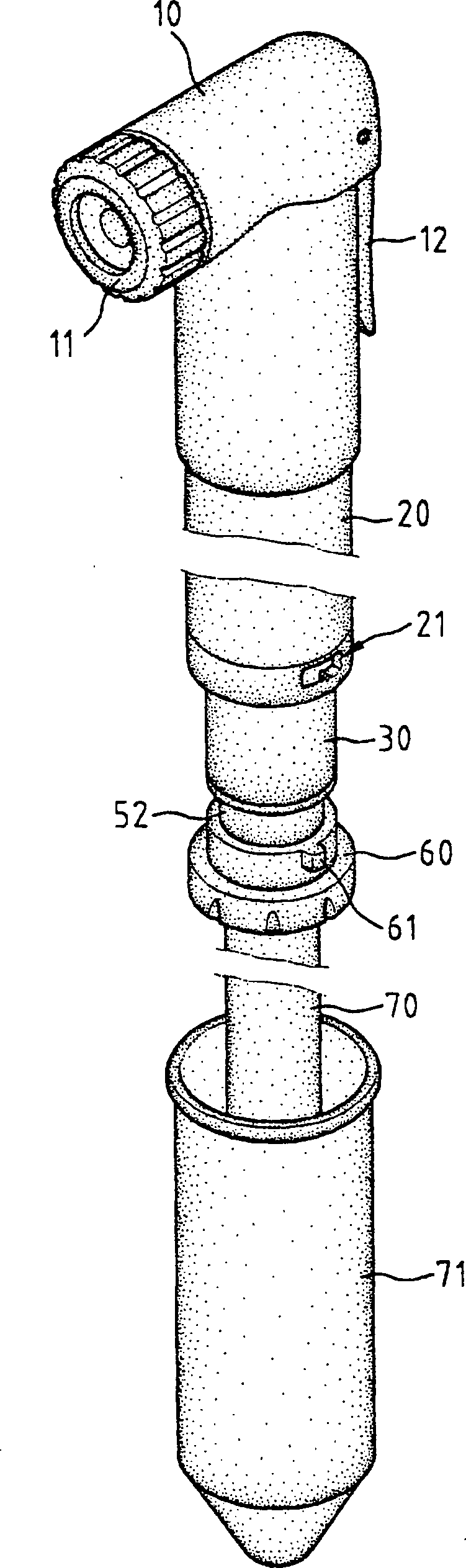
Figure 00000001
Figure 00000001

Description

Die vorliegende Erfindung betrifft eine Handluftpumpe, umfassend einen Kopf mit einem Luftauslaß, ein Außenrohr mit einem ersten Ende und einem zweiten Ende, eine hohle erste Kolbenstange mit einem ersten Ende, das sich hin und her bewegend im Außenrohr aufgenommen ist, und einem zweiten Ende, wobei am ersten Ende der hohlen ersten Kolbenstange ein verhältnismäßig großer Kolbenkopf fest zur Mitbewegung angebracht ist, eine zweite Kolbenstange mit einem ersten Ende, das sich hin und her bewegend in der hohlen ersten Kolbenstange aufgenommen ist, und einem zweiten Ende, wobei am ersten Ende der zweiten Kolbenstange ein verhältnismäßig kleiner Kolbenkopf fest zur Mitbewegung angebracht ist, und ein Betätigungshandgriff vorgesehen ist.The The present invention relates to a hand air pump, comprising a Head with an air outlet, an outer tube with a first end and a second end, a hollow first piston rod with a first end that reciprocates in the outer tube is recorded, and a second end, wherein at the first end of the hollow first piston rod a relatively large piston head fixed for co-movement attached, a second piston rod with a first end, that reciprocates in the hollow first piston rod is recorded, and a second end, wherein at the first end of the second piston rod a relatively small Piston head is firmly attached to the movement, and an operating handle is provided.

Handluftpumpen stellen ein nützliches, zweckmäßiges Werkzeug für Fahrräder dar und sie werden allgemein in zwei Typen entsprechend ihren Funktionen klassifiziert. Mehr im einzelnen, Handluftpumpen sind entweder dazu vorgesehen, Luft mit hohem Druck zu pumpen oder eine große Luftmenge zu pumpen. So ist aus der DE 195 18 242 A1 eine Druckerzeugungsvorrichtung bekannt, die Luft mit hohem Druck, jedoch volumenunabhängig erzeugen soll.Hand air pumps are a useful, convenient tool for bicycles and are generally classified into two types according to their functions. More specifically, hand air pumps are designed to either pump air at high pressure or to pump a large amount of air. So is from the DE 195 18 242 A1 known a pressure generating device that is to generate air at high pressure, but independent of volume.

Es besteht jedoch ein langes und nicht erfülltes Bedürfnis für eine Handluftpumpe, die beide Funktionen erfüllen kann.It however, there is a long and unfulfilled need for a manual air pump that does both functions fulfill can.

Aus der US 56 76 529 A ist eine Handluftpumpe bekannt, die einen Kopf mit einem Luftauslaß und ein Außenrohr mit einem ersten und einem zweiten Ende umfaßt. Eine hohle erste Kolbenstange ist mit einem Ende hin und her bewegend im Außenrohr aufgenommen, wobei an diesem Ende ein verhältnismäßig großer Kolbenkopf fest zur Mitwegung angebracht ist. Eine zweite Kolbenstange ist mit einem ersten Ende hin und her bewegend in der hohlen ersten Kolbenstange aufgenommen, wobei an diesem Ende ein verhältnismäßig kleiner Kolbenkopf fest zur Mitbewegung angebracht ist. Ferner ist ein Betätigungskopf vorgesehen. Diese Handluftpumpe dient zum Pumpen einer großen Luftmenge mit großem Druck. Sie hat zwei Betriebsarten, eine mit großem Volumen, bei der beide Kolben gleichzeitig arbeiten, und eine mit hohem Druck, bei der Luft nur aus dem Kolben mit der kleineren Bohrung arbeitet.From the US 56 76 529 A a hand-held air pump is known which comprises a head with an air outlet and an outer tube with a first and a second end. A hollow first piston rod is received with one end moving back and forth in the outer tube, a relatively large piston head being fixedly attached to the path at this end. A second piston rod is received with a first end moving back and forth in the hollow first piston rod, a relatively small piston head being fixedly attached to this movement at this end. An actuating head is also provided. This hand air pump is used to pump a large amount of air at high pressure. It has two operating modes, one with a large volume, in which both pistons work at the same time, and one with high pressure, in which air only works from the piston with the smaller bore.

Der Erfindung liegt die Aufgabe zugrunde, eine Handluftpumpe zu schaffen, die in der Lage ist, Luft mit hohem Druck zu pumpen und eine große Luftmenge zu pumpen. Diese Aufgabe ist erfindungsgemäß bei einer Handluftpumpe mit den Merkmalen des Anspruchs 1 gelöst. Weiterbildungen der erfindungsgemäßen Handluftpumpe sind Gegenstand der Unteransprüche.The The invention has for its object to provide a hand air pump, which is able to pump air at high pressure and a large amount of air to pump. This task is according to the invention with a hand air pump solved the features of claim 1. Developments of the manual air pump according to the invention are the subject of the subclaims.

Eine erfindungsgemäße Handluftpumpe umfaßt somit einen Kopf mit einem Luftauslaß, ein Außenrohr mit einem ersten Ende und einem zweiten Ende, eine hohle erste Kolbenstange mit einem ersten Ende, das sich hin und her bewegend im Außenrohr aufgenommen ist, und einem zweiten Ende, wobei am ersten Ende der hohlen ersten Kolbenstange ein verhältnismäßig großer Kolbenkopf fest zur Mitbewegung angebracht ist. Ferner ist eine zweite Kolbenstange mit einem ersten Ende, das sich hin und her bewegend in der hohlen ersten Kolbenstange aufgenommen ist, und einem zweiten Ende vorgesehen, wobei am ersten Ende der zweiten Kolbenstange ein verhältnismäßig kleiner Kolbenkopf fest zur Mitbewegung angebracht ist. Ein Betätigungshandgriff ist vorgesehen. Das erste Ende des Außenrohrs ist mit dem Kopf mit dem Luftauslaß verbunden. Am zweiten Ende der zweiten Kolbenstange ist der Betätigungshandgriff befestigt und es ist ein Schaltmittel vorgesehen, um es zu ermöglichen, daß die hohle erste Kolbenstange im Außenrohr hin und her bewegend bewegt wird, wenn es sich in einer ersten Position befindet, und um die hohle erste Kolbenstange in der Position zu halten, wenn es sich in einer zweiten Position befindet.A Manual air pump according to the invention comprises thus a head with an air outlet, an outer tube with a first end and a second end, a hollow first piston rod with a first end, which is received reciprocatingly in the outer tube, and a second end, being at the first end of the hollow first piston rod relatively large piston head is firmly attached to the movement. There is also a second piston rod with a first end that moves back and forth in the hollow first piston rod is received, and a second end is provided, being a relatively small one at the first end of the second piston rod Piston head is firmly attached to the movement. An operating handle is provided. The first end of the outer tube is with the head connected to the air outlet. At the second end of the second piston rod is the operating handle attached and a switching means is provided to enable it that the hollow first piston rod in the outer tube is moved back and forth when it is in a first position located and around the hollow first piston rod in position hold when it is in a second position.

Durch die Erfindung ist somit eine Zwei-Stufen-Handluftpumpe geschaffen worden, die leicht und einfach betätigbar ist. Die erfindungsgemäße Handluftpumpe ist in der Lage, in einer ersten Stufe eine erste Luftmenge zu pumpen und dann in einer zweiten Stufe Luft mit hohem Druck zu pumpen, um auf diese Weise die Reifen von Fahrrädern rasch aufzupumpen.By the invention is thus a two-stage hand air pump that is easy and simple to operate. The manual air pump according to the invention is able to pump a first amount of air in a first stage and then pumping air at high pressure in a second stage, to quickly inflate the tires of bicycles.

Die Erfindung wird im folgenden weiter anhand eines Ausführungsbeispiels und der Zeichnung beschrieben, wobei die Beschreibung lediglich zu Veranschaulichungszwecken dient und die Erfindung keineswegs einschränken soll. Auch soll die Erfindung nicht auf die speziellen in den Unteransprüchen angegebenen Merkmalskombinationen beschränkt sein. In der Zeichnung zeigen:The In the following, the invention will be further explained using an exemplary embodiment and the drawing, the description being only serves for purposes of illustration and the invention in no way restrict should. The invention is also not intended to be specific to that specified in the dependent claims Characteristic combinations may be limited. The drawing shows:

1 eine zum Teil fortgebrochene perspektivische Ansicht einer Zwei-Stufen-Handluftpumpe gemäß der vorliegenden Erfindung, 1 FIG. 2 is a partially broken perspective view of a two-stage hand air pump according to the present invention;

2 eine auseinandergezogene Ansicht der Handluftpumpe; 2 an exploded view of the hand pump;

3 und 4 seitliche Teilansichten, die die Funktion der Handluftpumpe veranschaulichen; 3 and 4 partial side views that illustrate the function of the manual air pump;

5 und 6 perspektivische Teilansichten, die die Schaltbetätigung der Handluftpumpe veranschaulichen; und 5 and 6 perspective partial views that illustrate the switching operation of the manual air pump; and

7 eine Schnitteilansicht der Handluftpumpe. 7 a sectional partial view of the hand air pump.

Es wird nun auf die Zeichnung und anfangs auf 1 und 2 Bezug genommen. Eine Zwei-Stufen-Handluftpumpe gemäß der vorliegenden Erfindung umfaßt allgemein einen Luftauslaßkopf 10, ein Außenrohr 20, eine hohle erste Kolbenstange 30 und eine zweiten Kolbenstange 70. Der Kopf 10 weist einen in einem ersten Ende vorgesehenen Auslaß 11 auf, durch den Luft in ein (nicht gezeigtes) Ventil eines (nicht gezeigten) Fahrradreifens gepumpt wird, der aufgepumpt werden soll. Der Kopf 10 umfaßt weiter einen Schalthebel 12, um den Kopf 10 sicher mit dem Ventil des Fahrradreifens in Eingriff zu bringen, der herkömmlich ist und daher nicht weiter beschrieben wird. Das Außenrohr 20 umfaßt ein mit dem Kopf 10 verbundenes erstes Ende. Das Außenrohr 20 umfaßt weiter einen im Umfang seines zweiten Endes vorgesehenen Schlitz 21. Wie in 5 gezeigt ist, ist ein Kanal 212 im Innenumfang des zweiten Endes des Außenrohrs 20 vorgesehen und steht mit dem Schlitz 21 in Verbindung. Eine den Schlitz 21 umgrenzende Außenwand umfaßt eine Eingriffsfläche 213 mit einem daran gebildeten Anschlag 2ll, der später beschrieben wird.It will now go to the drawing and initially 1 and 2 Referred. A two-stage hand air pump in accordance with the present invention generally includes an air outlet head 10 , an outer tube 20 , a hollow first piston rod 30 and a second piston rod 70 , The head 10 has an outlet provided in a first end 11 through which air is pumped into a valve (not shown) of a bicycle tire (not shown) to be inflated. The head 10 further includes a shift lever 12 to the head 10 to securely engage the valve of the bicycle tire, which is conventional and is therefore not described further. The outer tube 20 includes one with the head 10 connected first end. The outer tube 20 further includes a slot provided in the periphery of its second end 21 , As in 5 is shown is a channel 212 in the inner circumference of the second end of the outer tube 20 provided and stands with the slot 21 in connection. One the slot 21 surrounding outer wall comprises an engagement surface 213 with a stop formed on it 2ll which will be described later.

Die hohle erste Kolbenstange 30 umfaßt ein erstes Ende, das sich hin und her bewegend im Außenrohr 20 zum Pumpen von Luft aufgenommen ist. Das erste Ende der ersten Kolbenstange 30 umfaßt einen verhältnismäßig großen Kolbenkopf 32, der fest zur Mitbewegung angebracht ist. Die zweite Kolbenstange 70 umfaßt ein erstes Ende mit einem Innengewinde 72, das sich hin und her bewegend in der hohlen ersten Kolbenstange 30 aufgenommen ist, und einen Betätigungshandgriff 71, der an seinem zweiten Ende angebracht ist. Um die zweite Kolbenstange 70 herum angebracht befindet sich eine Eingriffshülse 50, die ein an ihrem ersten Ende gebildetes Außengewinde 51 und einen an ihrem zweiten Ende gebildeten abgestuften Abschnitt (siehe 52, 53 in 2) aufweist. Wie in 7 gezeigt ist, befindet sich das Außengewinde 51 der Eingriffshülse 50 mit einem Innengewinde 31 in einem zweiten Ende der ersten Kolbenstange 30 in Eingriff. Eine Haltehülse 60 ist um das zweite Ende der Eingriffshülse 50 herum angebracht, um dazwischen eine Feder 54 zu halten, wie am besten in 7 ge zeigt ist. Das zweite Ende der Eingriffshülse 50 umfaßt einen daran gebildeten Flansch 521 und die Haltehülse 60 umfaßt eine (nicht gezeichnete) Schulter für einen Eingriff mit dem Flansch 521, während die Feder 54 um den abgestuften Abschnitt 52, 53 herum angebracht ist, um die Schulter der Haltehülse 60 vorzuspannen, damit sie sicher mit dem Flansch 512 der Eingriffshülse 50 in Eingriff tritt. Die Haltehülse 60 umfaßt weiter wenigstens einen Teil oder Vorsprung 61, der an ihrem Außenumfang gebildet ist. Ein verhältnismäßig kleiner Kolbenkopf 40 (siehe 2) befindet sich mit dem ersten Ende der zweiten Kolbenstange 70 in Eingriff (siehe Gewinde 41 und 72) und ein O-Ring 42 ist um den Kolbenkopf 40 angebracht, um eine Dichtwirkung vorzusehen.The hollow first piston rod 30 includes a first end that reciprocates in the outer tube 20 for pumping air. The first end of the first piston rod 30 includes a relatively large piston head 32 which is firmly attached to the co-movement. The second piston rod 70 includes a first end with an internal thread 72 that is reciprocating in the hollow first piston rod 30 is included, and an operating handle 71 attached to its second end. To the second piston rod 70 An engagement sleeve is attached around it 50 which have an external thread formed at their first end 51 and a stepped portion formed at its second end (see 52 . 53 in 2 ) having. As in 7 is shown, the external thread is 51 the engagement sleeve 50 with an internal thread 31 in a second end of the first piston rod 30 engaged. A holding sleeve 60 is around the second end of the engagement sleeve 50 attached around with a spring in between 54 to keep as best in 7 is shown. The second end of the engagement sleeve 50 includes a flange formed thereon 521 and the holding sleeve 60 includes a shoulder (not shown) for engagement with the flange 521 while the spring 54 around the graded section 52 . 53 is attached around the shoulder of the holding sleeve 60 preload so they are secure with the flange 512 the engagement sleeve 50 engages. The holding sleeve 60 further includes at least a portion or protrusion 61 , which is formed on its outer circumference. A relatively small piston head 40 (please refer 2 ) is with the first end of the second piston rod 70 engaged (see thread 41 and 72 ) and an O-ring 42 is around the piston head 40 attached to provide a sealing effect.

Bei Beginn des Pumpens wird mit manueller Betätigung des Betätigungshandgriffs 71 die erste Kolbenstange 30 zusammen mit dem verhältnismäßig großen Kolbenkopf 32 im Außenrohr 20 hin- und hergehend bewegt, während die zweite Kolbenstange 70 zusammen mit dem verhältnismäßig kleinen Kolbenkopf 40 in der hohlen ersten Kolbenstange 30 hin- und hergehend bewegt wird. Dies bedeutet, daß eine große Luftmenge rasch über das Ventil in den Fahrradreifen gepumpt werden kann. Nach einem Zeitraum empfindet es der Benutzer mit Zunahme des Drucks im Inneren des Fahrradreifens immer schwieriger, Luft in den Fahrradreifen zu pumpen. Wie in 3 gezeigt ist, kann dann zu diesem Zeitpunkt der Benutzer die Haltehülse 60 nach oben bewegen, um den Keil 61 in den Kanal 212 zu bewegen (siehe 4 und 5), bis der Keil mit dem Schlitz 21 ausgerichtet ist. Wie in 6 gezeigt ist, wird dann die Haltehülse 60 durch einen Winkel bewegt, so daß sie den Keil 61 so druckbeaufschlagt, daß dieser durch den Anschlag 211 durchläuft, so daß er sicher mit der Eingriffsfläche 213 des Schlitzes 21 in Eingriff tritt. Es ist ersichtlich, daß der Anschlag 2ll aus Kunststoffmaterial hergestellt ist, so daß er den Keil 61 sicher in der Position hält, jedoch einen zwangsweisen Vorbeilauf des Keils 61 gestattet. Wie in 6 und 7 gezeigt ist, wird somit die erste Kolbenstange 30 in der Position gehalten (da sie sich in Eingriff mit der Haltehülse 60 befindet, die nun durch den Anschlag 211 in der Position gehalten wird) derart, daß lediglich die zweite Kolbenstange 70 in der ersten Kolbenstange 30 bei Handbetätigung des Betätigungshandgriffs 71 hin- und hergehend bewegt wird. Demzufolge braucht der Benutzer eine geringere Kraft aufzubringen, um Luft in den Fahrradreifen mit erhöhtem Luftdruck zu pumpen, da die Fläche des Kolbenkopfes 40 verhältnismäßig klein ist.At the start of pumping, the actuation handle is operated manually 71 the first piston rod 30 together with the relatively large piston head 32 in the outer tube 20 moved back and forth while the second piston rod 70 together with the relatively small piston head 40 in the hollow first piston rod 30 is moved back and forth. This means that a large amount of air can be pumped quickly through the valve in the bicycle tire. After a period of time, as the pressure inside the bicycle tire increases, the user finds it increasingly difficult to pump air into the bicycle tire. As in 3 is shown, the user can then hold the holding sleeve at this time 60 move up to the wedge 61 in the channel 212 to move (see 4 and 5 ) until the wedge with the slot 21 is aligned. As in 6 is shown, then the holding sleeve 60 moved through an angle so that it is the wedge 61 so pressurized that this by the stop 211 passes through so that it is safe with the engaging surface 213 of the slot 21 engages. It can be seen that the attack 2ll is made of plastic material so that it is the wedge 61 holds securely in position, but forcing the wedge to pass 61 allowed. As in 6 and 7 is shown, the first piston rod 30 held in position (since they are in engagement with the holding sleeve 60 located by the stop 211 is held in position) such that only the second piston rod 70 in the first piston rod 30 with manual operation of the operating handle 71 is moved back and forth. As a result, the user needs to apply less force to pump air into the bicycle tire with increased air pressure because of the area of the piston head 40 is relatively small.

Die Erfindung läßt sich wie folgt zusammenfassen: Eine Handluftpumpe umfaßt einen Kopf 10 mit einem Luftauslaß 11, ein Außenrohr 20, von dem ein erstes Ende mit dem Kopf verbunden ist, eine hohle erste Kolbenstange 30, von der ein Ende sich hin und her bewegend im Außenrohr aufgenommen ist, und eine zweite Kolbenstange 70, von der ein erstes Ende sich hin und her bewegend in der hohlen ersten Kolbenstange aufgenommen ist. Das erste Ende der hohlen ersten Kolbenstange 30 hat einen verhältnismäßig großen Kolbenkopf 32, der fest daran angebracht ist, um sich mitzubewegen. Ein zweites Ende der zweiten Kolbenstange 70 hat einen daran befestigten Betätigungshandgriff 71. Außerdem ist am ersten Ende der zweiten Kolbenstange ein verhältnismäßig kleiner Kolbenkopf 40 fest angebracht, um sich mitzubewegen. Eine Schalteinrichtung 50, 60 ist vorgesehen, um es zu ermöglichen, daß die hohle erste Kolbenstange im Außenrohr hin- und hergehend bewegt wird, wenn sie sich in einer ersten Postion befindet, und um die hohle erste Kolbenstange in der Position zu halten, wenn sie sich in einer zweiten Position befindet.The invention can be summarized as follows: A hand air pump comprises a head 10 with an air outlet 11 , an outer tube 20 , a first end of which is connected to the head, a hollow first piston rod 30 , one end of which is reciprocatingly received in the outer tube, and a second piston rod 70 , a first end of which is reciprocatingly received in the hollow first piston rod. The first end of the hollow first piston rod 30 has a relatively large piston head 32 , which is firmly attached to it to move with it. A second end of the second piston rod 70 has an operating handle attached to it 71 , There is also a relatively small piston head at the first end of the second piston rod 40 firmly attached to move around. A switching device 50 . 60 is provided to allow the hollow first piston rod to reciprocate in the outer tube when in a first position and to hold the hollow first piston rod in position when in a second position located.

Gemäß der obigen Beschreibung ist es ersichtlich, daß die Handluftpumpe gemäß der vorliegenden Erfindung eine Zwei-Stufen-Pumpbetätigung liefert, um effektiv, wirkungsvoll Luft in den Fahrradreifen zu pumpen, ohne daß eine Schwierigkeit bei der Kraftanwendung herbeigeführt wird. Die Handluftpumpe gemäß der vorliegenden Erfindung hat nämlich eine arbeitssparende Konstruktion. Weiter kann die Stufenschaltbetätigung der Handluftpumpe leicht und einfach durch Drehen der Haltehülse 60 bewerkstelligt werden.As described above, it can be seen that the manual air pump according to the present invention provides a two-stage pumping operation to effectively and effectively pump air into the bicycle tire without causing difficulty in the application of power. Namely, the hand air pump according to the present invention has a labor-saving construction. Furthermore, the tap changer actuation of the hand air pump can be easily and simply by turning the holding sleeve 60 be accomplished.

Claims (3)

Handluftpumpe, umfassend einen Kopf (10) mit einem Luftauslass (11), ein Außenrohr (20) mit einem ersten Ende, das mit dem Kopf (10) verbunden ist und einem zweiten Ende, eine hohle erste Kolbenstange (30) mit einem ersten Ende, das sich hin und her bewegend im Außenrohr aufgenommen ist, und einem zweiten Ende, wobei am ersten Ende der hohlen ersten Kolbenstange (30) ein verhältnismäßig großer Kolbenkopf (32) fest zur Mitbewegung angebracht ist, eine zweite Kolbenstange (70) mit einem ersten Ende, das sich hin und her bewegend in der hohlen ersten Kolbenstange (30) aufgenommen ist, wobei am ersten Ende der zweiten Kolbenstange ein verhältnismäßig kleiner Kolbenkopf (40) fest zur Mitbewegung angebracht ist, und einem zweiten Ende, an dem ein Betätigungshandgriff (71) vorgesehen ist, und einem Schaltmittel (50, 60), dadurch gekennzeichnet, dass das Schaltmittel (50, 60) eine Eingriffshülse (50) aufweist, die um die zweite Kolbenstange (70) herum angebracht ist und ein erstes Ende, das fest mit dem zweiten Ende der hohlen ersten Kolbenstange (30) in Eingriff steht, und ein zweites Ende aufweist, und eine Haltehülse (60) aufweist, die verschiebbar und drehbar um das zweite Ende der Eingriffshülse (50) herum angebracht ist, wobei das Außenrohr (20) ein Mittel (211, 213) zum lösbaren Ineingrifftreten mit der Haltehülse (60) aufweist, um es zu ermöglichen, dass die hohle erste Kolbenstange (30) im Außenrohr (20) hin und her bewegend bewegt wird, wenn es sich in einer ersten Position befindet, und um die hohle erste Kolbenstange (30) in der Position zu halten, wenn es sich in einer zweiten Position befindet.Hand air pump, comprising a head ( 10 ) with an air outlet ( 11 ), an outer tube ( 20 ) with a first end that ends with the head ( 10 ) is connected and a second end, a hollow first piston rod ( 30 ) with a first end that is reciprocatingly received in the outer tube and a second end, the hollow first piston rod ( 30 ) a relatively large piston head ( 32 ) is firmly attached to the movement, a second piston rod ( 70 ) with a first end that reciprocates in the hollow first piston rod ( 30 ) is accommodated, with a relatively small piston head () at the first end of the second piston rod ( 40 ) is firmly attached to the co-movement, and a second end on which an operating handle ( 71 ) is provided, and a switching means ( 50 . 60 ), characterized in that the switching means ( 50 . 60 ) an engagement sleeve ( 50 ) around the second piston rod ( 70 ) is attached around and a first end that is fixed to the second end of the hollow first piston rod ( 30 ) is engaged, and has a second end, and a holding sleeve ( 60 ) which is slidable and rotatable about the second end of the engagement sleeve ( 50 ) is attached around, the outer tube ( 20 ) a means ( 211 . 213 ) for releasable engagement with the holding sleeve ( 60 ) to allow the hollow first piston rod ( 30 ) in the outer tube ( 20 ) is moved back and forth when in a first position and around the hollow first piston rod ( 30 ) hold in position when in a second position. Handluftpumpe nach Anspruch 1, dadurch gekennzeichnet, dass die Haltehülse (60) einen am Außenumfang gebildeten Keil (61) aufweist und das Außenrohr (20) einen im zweiten Ende vorgesehenen Schlitz (21) aufweist, das zweite Ende des Außenrohrs einen in seinem Innenumfang vorgesehenen Kanal (212) aufweist, durch den der Keil (61) der Haltehülse (60) durchführbar ist, ein den Schlitz (21) aufweisender Umfang eine Eingriffsfläche (213) mit einem daran gebildeten Anschlag (211) aufweist, wobei der Anschlag (211) sicherstellt, dass der Keil (61) fest mit der Eingriffsfläche (213) in Eingriff triff, so dass er die Haltehülse (60) in der zweiten Position hält, aber eine zwangsweise Durchführung des Keils (61) gestattet.Hand air pump according to claim 1, characterized in that the holding sleeve ( 60 ) a wedge formed on the outer circumference ( 61 ) and the outer tube ( 20 ) a slot provided in the second end ( 21 ), the second end of the outer tube has a channel provided in its inner circumference ( 212 ) through which the wedge ( 61 ) the holding sleeve ( 60 ) is feasible, the slot ( 21 ) having an engagement surface ( 213 ) with a stop formed on it ( 211 ), the stop ( 211 ) ensures that the wedge ( 61 ) firmly with the engagement surface ( 213 ) so that it holds the holding sleeve ( 60 ) in the second position, but the wedge is forced through ( 61 ) allowed. Handluftpumpe nach Anspruch 1 oder 2, dadurch gekennzeichnet, dass das zweite Ende der Eingriffshülse (50) einen abgestuften Abschnitt (52, 53) mit einem daran gebildeten Flansch (521) aufweist und die Haltehülse (60) eine Schulter für ein in Ineingrifftreten mit dem abgestuften Abschnitt (52, 53) aufweist und weiter eine Feder (54) umfasst, die um den abgestuften Abschnitt (52, 53) herum angebracht ist, um die Schulter der Haltehülse für ein festes Ineingrifftreten mit dem abgestuften Abschnitt der Eingriffshülse vorzuspannen.Hand air pump according to claim 1 or 2, characterized in that the second end of the engagement sleeve ( 50 ) a graded section ( 52 . 53 ) with a flange formed on it ( 521 ) and the holding sleeve ( 60 ) a shoulder for engaging the stepped portion ( 52 . 53 ) and a spring ( 54 ) that surrounds the stepped section ( 52 . 53 ) is attached around to bias the shoulder of the holding sleeve for firm engagement with the stepped portion of the engaging sleeve.
DE1998129695 1998-07-02 1998-07-02 Two-step manual air pump Expired - Fee Related DE19829695C5 (en)

Priority Applications (2)

Application Number Priority Date Filing Date Title
DE29824653U DE29824653U1 (en) 1998-07-02 1998-07-02 Two-stage hand air pump
DE1998129695 DE19829695C5 (en) 1998-07-02 1998-07-02 Two-step manual air pump

Applications Claiming Priority (1)

Application Number Priority Date Filing Date Title
DE1998129695 DE19829695C5 (en) 1998-07-02 1998-07-02 Two-step manual air pump

Publications (3)

Publication Number Publication Date
DE19829695A1 DE19829695A1 (en) 2000-01-13
DE19829695C2 DE19829695C2 (en) 2000-06-15
DE19829695C5 true DE19829695C5 (en) 2004-12-23

Family

ID=7872831

Family Applications (1)

Application Number Title Priority Date Filing Date
DE1998129695 Expired - Fee Related DE19829695C5 (en) 1998-07-02 1998-07-02 Two-step manual air pump

Country Status (1)

Country Link
DE (1) DE19829695C5 (en)

Families Citing this family (7)

* Cited by examiner, † Cited by third party
Publication number Priority date Publication date Assignee Title
US6135733A (en) * 2000-02-07 2000-10-24 Wu; Scott Manual air pump having selectable high pressure and low pressure modes
TW431558U (en) * 2000-08-11 2001-04-21 Topeak Inc Improved air pump structure
US6615704B2 (en) * 2001-12-13 2003-09-09 Louis Chuang Tire pump handle that may be operated between a locking position and a non-locking position by one hand only
TW563663U (en) * 2002-06-11 2003-11-21 Shu-Mu Wu Improved clamping and retaining structure for air pump
TWI267582B (en) * 2005-11-24 2006-12-01 Shu-Mu Wu Improvement of a miniature air pump
DE102009034198A1 (en) 2009-07-22 2011-02-03 Sks Metaplast Scheffer-Klute Gmbh Pump for a two-wheeled tire
DE102024122904A1 (en) * 2024-08-12 2026-02-12 Daysaver Ag air pump

Citations (3)

* Cited by examiner, † Cited by third party
Publication number Priority date Publication date Assignee Title
DE19518242A1 (en) * 1995-05-15 1996-11-21 Innovative Technik Marketing U Device for generating a pressure
US5676529A (en) * 1996-07-15 1997-10-14 Hermansen; Frank Compact manual air pump having selectable high volume and high pressure modes
US5779457A (en) * 1996-03-29 1998-07-14 Chuang; Louis Hand pump for pumping air of lower pressure and high pressure

Patent Citations (3)

* Cited by examiner, † Cited by third party
Publication number Priority date Publication date Assignee Title
DE19518242A1 (en) * 1995-05-15 1996-11-21 Innovative Technik Marketing U Device for generating a pressure
US5779457A (en) * 1996-03-29 1998-07-14 Chuang; Louis Hand pump for pumping air of lower pressure and high pressure
US5676529A (en) * 1996-07-15 1997-10-14 Hermansen; Frank Compact manual air pump having selectable high volume and high pressure modes

Also Published As

Publication number Publication date
DE19829695C2 (en) 2000-06-15
DE19829695A1 (en) 2000-01-13

Similar Documents

Publication Publication Date Title
DE10225207B4 (en) pump
EP0120309A2 (en) Pneumatic-hydraulic setting tool for blind rivet nuts
DE19707041A1 (en) Quick connector
DE2750472C2 (en)
DE19829695C5 (en) Two-step manual air pump
DE10200245A1 (en) Tire pump for bicycle, has switch which can be moved between position in which end of cylinder is fixed on end of handle, and position in which end of cylinder is retracted into end of handle
DE3590297C2 (en)
DE60200013T2 (en) Device for correcting automobile body panels
DE1954656A1 (en) Power-driven impact turning tool
EP0252208A1 (en) Pressure fluid driven cylinder
DE29900048U1 (en) Rivet setting tool with reversing device
DE19812961C2 (en) Valve coupling piece
DE4434508A1 (en) Air pump
DE2607263A1 (en) PNEUMATIC BLIND RIVETING TOOL
EP1160451B1 (en) Piston pump
EP4155141B1 (en) Connecting device for connecting a pneumatic tyre inflation valve to a compressed air source
DE202007000487U1 (en) Bicycle pump, comprises segment with air outlet protected inside outer shaft for storage and transport
DE19927955C2 (en) Valve coupling piece for a pump device of the swing lever type for use with various valves
DE2439589A1 (en) MULTI-POSITION MULTI-WAY VALVE
DE29824653U1 (en) Two-stage hand air pump
DE3219011A1 (en) DEVICE FOR SCREWING IN THREADED PINS
DE19821512C2 (en) Pump device with swivel device for various valves
DE20214032U1 (en) Toggle clamp
DE10030762C2 (en) Pump device with swiveling inner tube for different valves
DE2223999C2 (en) Inlet and outlet valve arrangement for the working displacement of a pneumatic nailer

Legal Events

Date Code Title Description
OP8 Request for examination as to paragraph 44 patent law
D2 Grant after examination
8363 Opposition against the patent
8328 Change in the person/name/address of the agent

Free format text: PATENTANWAELTE VON KREISLER, SELTING, WERNER ET COL., 50667 KOELN

8366 Restricted maintained after opposition proceedings
8392 Publication of changed patent specification
R119 Application deemed withdrawn, or ip right lapsed, due to non-payment of renewal fee

Effective date: 20130201