DE19829783B4 - Sliding door or partition wall system - Google Patents
Sliding door or partition wall system Download PDFInfo
- Publication number
- DE19829783B4 DE19829783B4 DE1998129783 DE19829783A DE19829783B4 DE 19829783 B4 DE19829783 B4 DE 19829783B4 DE 1998129783 DE1998129783 DE 1998129783 DE 19829783 A DE19829783 A DE 19829783A DE 19829783 B4 DE19829783 B4 DE 19829783B4
- Authority
- DE
- Germany
- Prior art keywords
- wing
- sealing strip
- partition wall
- sliding
- sliding door
- Prior art date
- Legal status (The legal status is an assumption and is not a legal conclusion. Google has not performed a legal analysis and makes no representation as to the accuracy of the status listed.)
- Expired - Lifetime
Links
Classifications
-
- E—FIXED CONSTRUCTIONS
- E06—DOORS, WINDOWS, SHUTTERS, OR ROLLER BLINDS IN GENERAL; LADDERS
- E06B—FIXED OR MOVABLE CLOSURES FOR OPENINGS IN BUILDINGS, VEHICLES, FENCES OR LIKE ENCLOSURES IN GENERAL, e.g. DOORS, WINDOWS, BLINDS, GATES
- E06B7/00—Special arrangements or measures in connection with doors or windows
- E06B7/16—Sealing arrangements on wings or parts co-operating with the wings
- E06B7/22—Sealing arrangements on wings or parts co-operating with the wings by means of elastic edgings, e.g. elastic rubber tubes; by means of resilient edgings, e.g. felt or plush strips, resilient metal strips
- E06B7/23—Plastic, sponge rubber, or like strips or tubes
- E06B7/2316—Plastic, sponge rubber, or like strips or tubes used as a seal between the floor and the wing
-
- E—FIXED CONSTRUCTIONS
- E04—BUILDING
- E04B—GENERAL BUILDING CONSTRUCTIONS; WALLS, e.g. PARTITIONS; ROOFS; FLOORS; CEILINGS; INSULATION OR OTHER PROTECTION OF BUILDINGS
- E04B2/00—Walls, e.g. partitions, for buildings; Wall construction with regard to insulation; Connections specially adapted to walls
- E04B2/74—Removable non-load-bearing partitions; Partitions with a free upper edge
- E04B2/82—Removable non-load-bearing partitions; Partitions with a free upper edge characterised by the manner in which edges are connected to the building; Means therefor; Special details of easily-removable partitions as far as related to the connection with other parts of the building
- E04B2/827—Partitions constituted of sliding panels
Landscapes
- Engineering & Computer Science (AREA)
- Architecture (AREA)
- Civil Engineering (AREA)
- Structural Engineering (AREA)
- Physics & Mathematics (AREA)
- Electromagnetism (AREA)
- Specific Sealing Or Ventilating Devices For Doors And Windows (AREA)
Abstract
Schiebetür- oder
Trennwandanlage,
mit mindestens einem Schiebeflügel, der
an seinem oberen Rand in einer Deckenschiene geführt ist,
mit einer an
seinem unteren Rand auf- und abbewegbarn Bodendichtung, die eine über eine
flügelseitig
abgestützte Feder
nach unten zum Boden hin beaufschlagte Dichtleiste aufweist,
wobei
die Feder zwischen der Unterkante des Flügels und der Dichtleiste angeordnet
und als Schraubendruckfeder ausgebildet ist,
dadurch gekennzeichnet,
dass
die Dichtleiste (4) mit mindestens einem Führungsstift (3) zusammenwirkt,
der entweder flügelfest
oder dichtleistenfest angeordnet ist und ein Führungsloch in der Dichtleiste
(4) bzw. im Flügel
(10) durchgreift,
wobei die Feder (5) als konzentrisch um den
Führungsstift (3)
angeordnete Schraubendruckfeder (5) ausgebildet ist, und
wobei
die Dichtleiste (4) bodenseitig einen Gleit- oder Laufkörper (8)
aufweist.Sliding door or partition wall system,
with at least one sliding leaf, which is guided at its upper edge in a ceiling rail,
with a bottom seal which can be moved up and down at its lower edge and which has a sealing strip which is acted upon downward by a wing-side supported spring downwards towards the bottom,
wherein the spring is arranged between the lower edge of the wing and the sealing strip and designed as a helical compression spring,
characterized,
in that the sealing strip (4) interacts with at least one guide pin (3) which is either fixed to the wing or fixed to the sealing strip and passes through a guide hole in the sealing strip (4) or in the wing (10),
wherein the spring (5) as concentrically around the guide pin (3) arranged helical compression spring (5) is formed, and
wherein the sealing strip (4) on the bottom side has a sliding or running body (8).
Description
Die Erfindung betrifft eine Schiebetür- oder Trennwandanlage mit den Merkmalen des Oberbegriffs des Patentanspruchs 1.The Invention relates to a sliding door or partition wall system with the features of the preamble of the claim 1.
Aus
der
Aus
der
Motorisch
angetriebene Raumtrennwände sind
auch aus
Aus
der
Aus
der
Der Erfindung liegt die Aufgabe zugrunde, eine Schiebe- oder Trennwandanlage mit einem einfachen Bodendichtungssystem ohne Fremdenergieantrieb zur Betätigung der Bodendichtung zu schaffen.Of the Invention is based on the object, a sliding or partition wall system with a simple floor seal system without external power drive for operation to create the bottom seal.
Erfindungsgemäß wird die Aufgabe durch die Merkmale des Patentanspruchs 1 gelöst.According to the invention Problem solved by the features of claim 1.
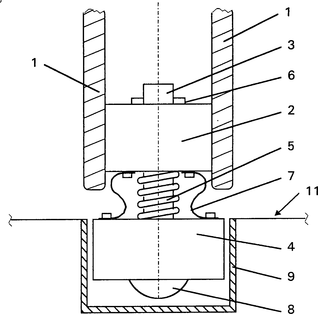
Die Dichtleiste wirkt mit mindestens einem Führungsstift zusammen, der entweder flügelfest oder dichtleistenfest angeordnet ist und ein Führungsloch in der Dichtleiste bzw. im Flügel durchgreift. Die Feder ist als konzentrisch um den Führungsstift angeordnete Schraubendruckfeder ausgebildet. Die Dichtleiste weist bodenseitig einen Gleit- oder Laufkörper auf.The Sealing strip cooperates with at least one guide pin, which either winged or Dichtleistenfest is arranged and a guide hole in the sealing strip or in the wing be upheld. The spring is considered concentric around the guide pin arranged helical compression spring formed. The sealing strip points on the bottom side a sliding or running body.
Die an der Unterkante des Flügelelements angeordnete Bodenleiste oder Bodendichtleiste kann in eine im Boden eingelassene Führungsschiene eingreifen. Zwischen der Unterkante des Flügelelements und der Bodenleiste können eine oder mehrere Federn angeordnet sein, die die Bodenleiste nach unten zum Boden hin beaufschlagen. Ein zwischen Flügelunterkante und Dichtleiste angeordneter Gummibalg gewährleistet eine formschlüssige Abdichtung. Vorzugsweise kann auf beiden Seiten des Flügelelements ein jeweils die Federn und gegebenenfalls die Führungsstifte abdeckender Gummibalg angeordnet sein. Alternativ kann der Balg auch selbst als die Feder ausgebildet sein.The arranged at the lower edge of the wing element Bottom rail or floor sealing strip can be embedded in a floor guide rail intervention. Between the lower edge of the wing element and the bottom strip can one or more springs can be arranged down the bottom bar apply to the ground. One between lower edge of wing and sealing strip arranged rubber bellows guaranteed a form-fitting Seal. Preferably, on both sides of the wing element a respectively the springs and possibly the guide pins covering rubber bellows be arranged. Alternatively, the bellows itself as the spring be educated.
Die vorzugsweise im Boden eingelassene Führungsschiene ist endseitig mit einer Anlaufschräge als Übergang zur Bodengleiche versehen.The preferably in the ground recessed guide rail is the end with a run-on slope as a transition provided to the ground level.
Deckenseitig ist das Flügelelement in einer oberen Laufschiene, sogenannte Deckenlaufschiene, geführt. Die Deckenlaufschiene ist in vertikaler Flügelebene fluchtend mit der bodenseitigen Führungsschiene angeordnet, vorzugsweise verlaufen beide geradlinig. Über den Verlauf der bodenseitigen Führungsschiene axial hinaus verläuft die Deckenlaufschiene vorzugsweise kurvenförmig gebogen, um das Flügelelement in eine seitliche Parkposition verfahren zu können. Vorzugsweise sind mehrere Flügelelemente vorgesehen, die in dem ersten linearen Abschnitt in der Deckenlaufschiene und der bodenseitigen Führungsschiene linear nebeneinander verfahrbar sind unter Ausbildung einer gemeinsamen fluchtenden Flügelebene, in der die Flügelelemente auch in der Geschlossenstellung der Türanlage stehen. Beim Öffnen werden die Flügelelemente über die Deckenlaufschiene geführt in die seitliche Parkposition (Bahnhof) verfahren. Hierbei werden die Bodendichtleisten der Reihenfolge nach von der Anlaufschräge auf Bodengleiche in der Parkposition bzw. im sogenannten Bahnhofsbereich angehoben. In der Parkposition, in der keine Bodenlaufschienen angeordnet sind, sondern die Bodendichtungen auf dem Boden laufen, können die Flügelelemente in Stapelanordnung stehen.ceiling side is the wing element in an upper track rail, so-called ceiling track rail out. The Ceiling track is in vertical wing plane aligned with the bottom guide rail arranged, preferably both extend straight. On the Course of the bottom guide rail axially out the ceiling runner preferably curved curved to the wing element to be able to move into a lateral parking position. Preferably, several wing elements provided in the first linear section in the overhead track rail and the bottom guide rail linearly movable side by side to form a common aligned Wing plane, in the wing elements too in the closed position of the door system stand. When opening become the wing elements over the Ceiling track rail out move to the side parking position (station). Here are the bottom sealing strips in order from the starting slope to ground level raised in the parking position or in the so-called station area. In the parking position, where no floor rails are arranged, but the bottom seals can run on the ground, the wing elements stand in a stacked arrangement.
Vorzugsweise zwei an der Unterseite der Bodenleiste gleitend gelagerte Laufkugeln oder dergleichen ermöglichen das Abrollen der an den Deckenlaufschienen geführten Flügelelemente. Vorzugsweise laufen die Laufkugeln lediglich auf der Bodengleiche, d.h. lediglich außerhalb der bodenseitigen Führungsschiene und eventuell im Bereich der Anlaufschräge. Innerhalb der bodenseitigen Führungsschiene müssen sie nicht, können aber auf dem Nutgrund der Bodenlaufschiene laufen. Zur seitlichen Führung innerhalb der Führungsschiene können die Seitenwandungen oder Dichtleiste in der Führungsschiene gleiten.Preferably, two slidably mounted on the underside of the bottom bar running balls or the like Chen allow the rolling of guided on the ceiling rails wing elements. Preferably, the running balls run only on the ground level, ie only outside the bottom guide rail and possibly in the range of the starting slope. Within the bottom guide rail they do not have, but can run on the groove bottom of the bottom rail. For lateral guidance within the guide rail, the side walls or sealing strip can slide in the guide rail.
Die Flügelelemente können manuell oder elektromotorisch angetrieben werden, z.B. durch am Flügelelement montierte Antriebsmotoren.The wing elements can be driven manually or by electric motor, e.g. through on the wing element mounted drive motors.
Ein weiterer Vorteil der Erfindung besteht darin, dass die in die Führungsschiene abgesenkte Bodenleiste ein Aufdrücken des Flügels senkrecht zur Verschieberichtung verhindert.One Another advantage of the invention is that in the guide rail lowered bottom bar a pressing of the grand piano prevented perpendicular to the direction of displacement.
Weitere besonders bevorzugte Merkmale der Erfindung ergeben sich aus den Unteransprüchen 2 bis 12 sowie der Figurenbeschreibung.Further particularly preferred features of the invention will become apparent from the dependent claims 2 to 12 and the description of the figures.
Dabei zeigt:there shows:
Bei
dem in den
Am
unteren horizontalen Rand des Schiebeflügels
In
der Schließlage
greift die Dichtleiste
Die gesamte Anordnung ermöglicht eine präzise Führung und stabile Parkstellung der Schiebetrennwandanlage mit geringem technischem Aufwand.The entire arrangement allows a precise one guide and stable parking position of the sliding partition wall system with low technical effort.
In
Wegen
des erforderlichen geometrischen Bewegungsradius der Bodenleiste
Claims (8)
Priority Applications (1)
| Application Number | Priority Date | Filing Date | Title |
|---|---|---|---|
| DE1998129783 DE19829783B4 (en) | 1998-07-03 | 1998-07-03 | Sliding door or partition wall system |
Applications Claiming Priority (1)
| Application Number | Priority Date | Filing Date | Title |
|---|---|---|---|
| DE1998129783 DE19829783B4 (en) | 1998-07-03 | 1998-07-03 | Sliding door or partition wall system |
Publications (2)
| Publication Number | Publication Date |
|---|---|
| DE19829783A1 DE19829783A1 (en) | 2000-01-05 |
| DE19829783B4 true DE19829783B4 (en) | 2006-12-28 |
Family
ID=7872893
Family Applications (1)
| Application Number | Title | Priority Date | Filing Date |
|---|---|---|---|
| DE1998129783 Expired - Lifetime DE19829783B4 (en) | 1998-07-03 | 1998-07-03 | Sliding door or partition wall system |
Country Status (1)
| Country | Link |
|---|---|
| DE (1) | DE19829783B4 (en) |
Families Citing this family (8)
| Publication number | Priority date | Publication date | Assignee | Title |
|---|---|---|---|---|
| DE10101514C2 (en) * | 2001-01-12 | 2003-03-06 | Dorma Gmbh & Co Kg | Floor guide for a door leaf of a sliding door |
| EP1249548B1 (en) * | 2001-04-12 | 2016-04-06 | H & T Raumdesign AG | Wall element of a sliding wall |
| FI119253B (en) * | 2006-08-16 | 2008-09-15 | Lumon Oy | With a sealing panel design and panel system |
| DE102012106419A1 (en) | 2012-07-17 | 2014-01-23 | Eduard Schlecht | MODULE FOR RECEIVING A SLIDING DOOR, FLOATING COMPONENT FOR A MODULE FOR RECEIVING A SLIDING DOOR AND METHOD FOR MOUNTING A MODULE FOR A SLIDING DOOR |
| CN103643872B (en) * | 2013-12-11 | 2015-05-06 | 中国建筑标准设计研究院 | Novel track sealing device |
| IT201800009597A1 (en) | 2018-10-19 | 2020-04-19 | Unifor Spa | MODULAR PANEL DIVIDING WALL |
| CN110130788B (en) * | 2019-05-29 | 2021-09-10 | 青岛中科汉维实验室装备科技有限公司 | Combined slideway for lifting glass window of ventilation cabinet |
| CN111608542A (en) * | 2020-04-22 | 2020-09-01 | 滁州市银达门窗有限公司 | Translational push-pull type soundproof window and production method thereof |
Citations (5)
| Publication number | Priority date | Publication date | Assignee | Title |
|---|---|---|---|---|
| DE2404875A1 (en) * | 1974-02-01 | 1975-08-14 | Hueppe Justin Fa | Partitioning wall suspended on support rails - has motor actuating wall and ceiling elements |
| EP0509961A1 (en) * | 1991-04-17 | 1992-10-21 | Planet MJT AG | Sealing arrangement, particularly for door wings |
| EP0311752B1 (en) * | 1987-10-15 | 1993-01-27 | Karl Haab | Truck to couple plate sliding elements |
| DE9209496U1 (en) * | 1992-07-15 | 1993-11-18 | Hüppe Form Sonnenschutz- und Raumtrennsysteme GmbH, 26133 Oldenburg | Control device for controlling a drive device of a room partition |
| EP0595000A2 (en) * | 1992-10-28 | 1994-05-04 | ABOPART VIOL UND PARTNER GmbH & Co. KG. | Movable wall element for a partition |
-
1998
- 1998-07-03 DE DE1998129783 patent/DE19829783B4/en not_active Expired - Lifetime
Patent Citations (5)
| Publication number | Priority date | Publication date | Assignee | Title |
|---|---|---|---|---|
| DE2404875A1 (en) * | 1974-02-01 | 1975-08-14 | Hueppe Justin Fa | Partitioning wall suspended on support rails - has motor actuating wall and ceiling elements |
| EP0311752B1 (en) * | 1987-10-15 | 1993-01-27 | Karl Haab | Truck to couple plate sliding elements |
| EP0509961A1 (en) * | 1991-04-17 | 1992-10-21 | Planet MJT AG | Sealing arrangement, particularly for door wings |
| DE9209496U1 (en) * | 1992-07-15 | 1993-11-18 | Hüppe Form Sonnenschutz- und Raumtrennsysteme GmbH, 26133 Oldenburg | Control device for controlling a drive device of a room partition |
| EP0595000A2 (en) * | 1992-10-28 | 1994-05-04 | ABOPART VIOL UND PARTNER GmbH & Co. KG. | Movable wall element for a partition |
Also Published As
| Publication number | Publication date |
|---|---|
| DE19829783A1 (en) | 2000-01-05 |
Similar Documents
| Publication | Publication Date | Title |
|---|---|---|
| EP0327727B1 (en) | Guiding device for a vertically slidable window | |
| EP3963159B1 (en) | Sliding door with a sliding wing | |
| EP3488065A1 (en) | Floor sill system for a displaceable sash as a sliding sash or displaceable lift-and-slide sash of a window or of a door | |
| DE102017130912A1 (en) | Lift-slide door with a barrier-free threshold | |
| WO2018166811A1 (en) | Floor sill system for a displaceable sash as a sliding sash or displaceable lift-and-slide sash of a window or of a door | |
| DE19829783B4 (en) | Sliding door or partition wall system | |
| EP3219893A1 (en) | Central seal block for a sliding/lifting door | |
| EP2083144B1 (en) | Gate, in particular sectional gate, and gate drive | |
| DE102005002179A1 (en) | Wing arrangement with moving wing and fixed wing | |
| EP2157898B1 (en) | Sliding door and shower partition with sliding door | |
| EP2703591A2 (en) | Sealing device for sliding windows or sliding doors | |
| EP3608494B1 (en) | Lifting device for a sliding door or sliding window | |
| EP2402546A2 (en) | Door system | |
| DE3235026C2 (en) | ||
| EP3879059B1 (en) | Floor threshold | |
| EP1870549A2 (en) | Sectional gate | |
| DE3343498C2 (en) | Roof element | |
| EP3179022B1 (en) | Gate, especially sectional gate and gate drive | |
| DE102007016815A1 (en) | sliding door system | |
| AT526424B1 (en) | Management system | |
| EP2322747B1 (en) | Sliding door assembly | |
| EP3708751B1 (en) | Guiding system for sliding doors | |
| EP0309511A1 (en) | Gate, in particular a motor-driven industrial gate | |
| DE10321547C5 (en) | Automatic sliding door | |
| AT526423B1 (en) | Arrangement with structure, cover element and guide system |
Legal Events
| Date | Code | Title | Description |
|---|---|---|---|
| 8110 | Request for examination paragraph 44 | ||
| 8364 | No opposition during term of opposition | ||
| R120 | Application withdrawn or ip right abandoned |