DE19829953B4 - Laser Scanning Microscope - Google Patents
Laser Scanning Microscope Download PDFInfo
- Publication number
- DE19829953B4 DE19829953B4 DE19829953.2A DE19829953A DE19829953B4 DE 19829953 B4 DE19829953 B4 DE 19829953B4 DE 19829953 A DE19829953 A DE 19829953A DE 19829953 B4 DE19829953 B4 DE 19829953B4
- Authority
- DE
- Germany
- Prior art keywords
- range
- illumination
- beam path
- beam splitter
- dichroic
- Prior art date
- Legal status (The legal status is an assumption and is not a legal conclusion. Google has not performed a legal analysis and makes no representation as to the accuracy of the status listed.)
- Expired - Lifetime
Links
- 238000005286 illumination Methods 0.000 claims abstract description 19
- 230000008878 coupling Effects 0.000 claims abstract description 8
- 238000010168 coupling process Methods 0.000 claims abstract description 8
- 238000005859 coupling reaction Methods 0.000 claims abstract description 8
- 238000001514 detection method Methods 0.000 claims abstract description 6
- 230000005855 radiation Effects 0.000 claims description 6
- 239000013307 optical fiber Substances 0.000 claims description 3
- 230000005284 excitation Effects 0.000 abstract description 2
- 238000000926 separation method Methods 0.000 abstract description 2
- 238000003384 imaging method Methods 0.000 description 3
- 230000003287 optical effect Effects 0.000 description 2
- 238000004624 confocal microscopy Methods 0.000 description 1
- 238000005516 engineering process Methods 0.000 description 1
- 239000000835 fiber Substances 0.000 description 1
- 239000000203 mixture Substances 0.000 description 1
- 238000012544 monitoring process Methods 0.000 description 1
- 230000007935 neutral effect Effects 0.000 description 1
- 238000002310 reflectometry Methods 0.000 description 1
- 238000011144 upstream manufacturing Methods 0.000 description 1
Images

Classifications
-
- G—PHYSICS
- G02—OPTICS
- G02B—OPTICAL ELEMENTS, SYSTEMS OR APPARATUS
- G02B21/00—Microscopes
- G02B21/0004—Microscopes specially adapted for specific applications
- G02B21/002—Scanning microscopes
- G02B21/0024—Confocal scanning microscopes (CSOMs) or confocal "macroscopes"; Accessories which are not restricted to use with CSOMs, e.g. sample holders
- G02B21/0052—Optical details of the image generation
- G02B21/0064—Optical details of the image generation multi-spectral or wavelength-selective arrangements, e.g. wavelength fan-out, chromatic profiling
-
- G—PHYSICS
- G02—OPTICS
- G02B—OPTICAL ELEMENTS, SYSTEMS OR APPARATUS
- G02B21/00—Microscopes
- G02B21/0004—Microscopes specially adapted for specific applications
- G02B21/002—Scanning microscopes
Landscapes
- Physics & Mathematics (AREA)
- Chemical & Material Sciences (AREA)
- Analytical Chemistry (AREA)
- General Physics & Mathematics (AREA)
- Optics & Photonics (AREA)
- Spectroscopy & Molecular Physics (AREA)
- Microscoopes, Condenser (AREA)
Abstract
In Laser-Scanning-Mikroskopen werden zum Einkoppeln unterschiedlicher Beleuchtungswellenlängen bisher mehrere und/oder wechselbare Strahlteiler verwendet, was aufwendig ist beziehungsweise zu Justierproblemen führt.
Um eine spektral flexiblere Anregung ohne Justierprobleme zu ermöglichen, ist neben einem dichroitischen Hauptstrahlteiler zur Trennung von Beleuchtungsstrahlengang und Detektionsstrahlengang ein dichroitischer Strahlteiler im Beleuchtungsstrahlengang zur Einkopplung der Beleuchtung vorgesehen, der im UV- und IR-Bereich reflektierend und im sichtbaren Bereich transmittierend oder im IR- und UV-Bereich transmittierend und im sichtbaren Bereich reflektierend ausgebildet ist. Alternativ sind neben dem Hauptstrahlteiler ein erster dichroitischen Strahlteiler im Beleuchtungsstrahlengang zur Einkopplung der Beleuchtung, der im UV-Bereich reflektierend und im IR-Bereich und im VIS-Bereich transmittierend ist, und ein zweiter dichroitischer Strahlteiler im Beleuchtungsstrahlengang, der im sichtbaren Bereich reflektierend und IR-Bereich transmittierend ausgebildet ist, vorgesehen.In laser scanning microscopes, several and / or exchangeable beam splitters are used for coupling different illumination wavelengths, which is expensive or leads to adjustment problems.
In order to enable spectrally more flexible excitation without adjustment problems, a dichroic beam splitter in the illumination beam path for coupling the illumination is provided in addition to a dichroic main beam splitter for the separation of the illumination beam path and detection beam path, which is reflective in the UV and IR range and transmissive in the visible range or in the IR range. and UV-transmitting and reflective in the visible range is formed. Alternatively, in addition to the main beam splitter, a first dichroic beam splitter in the illumination beam path for coupling the illumination, which is reflective in the UV range and transmissive in the IR range and in the VIS range, and a second dichroic beam splitter in the illumination beam path, which is reflective in the visible range and IR Area is formed transmissive, provided.

Description
Die Erfindung betrifft ein Laser-Scanning-Mikroskop mit rasterförmiger Beleuchtung mittels Laserstrahlung unter unterschiedlichen Wellenlängen.The invention relates to a laser scanning microscope with grid-like illumination by means of laser radiation at different wavelengths.
Zum Stand der Technik wird verwiesen auf K. Winkler, W. Knebel: ”Leica TCS 4D UV – Das Systemkonzept für die Multiparameter-Konfokalmikroskopie”; Mitteilungen für Wissenschaft und Technik, Bd. XI, Nr. 1, S. 9–19, Juni 1995, sowie auf
Der Erfindung liegt die Aufgabe zugrunde, eine spektral flexiblere Anregung ohne Justierprobleme zu ermöglichen.The invention has for its object to enable a spectrally more flexible excitation without adjustment problems.
Die Aufgabe wird erfindungsgemäß durch ein Laser-Scanning-Mikroskop gemäß Anspruch 1 oder 3 gelöst.The object is achieved by a laser scanning microscope according to
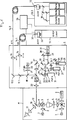
In
Der Scankopf S kann sowohl an den Phototubus eines aufrechten Mikroskopes sowie auch an einen seitlichen Ausgang eines inversen Mikroskopes angesetzt werden.The scan head S can be attached both to the phototube of an upright microscope and to a lateral exit of an inverted microscope.
Es ist ein zwischen Auflichtscan und Durchlichtscan mittels eines schwenkbaren Spiegels
Auch die Mischung der Strahlung verschiedener Laser am Fasereingang ist möglich und kann anhand der schematisch dargestellten, auswechselbaren und schaltbaren Teilerspiegel
Die Einkopplung der Lichtleitfasern
Mittels eines teildurchlässigen Spiegels
Die eigentliche Scaneinheit besteht aus Scanningobjektiv
Ein Umlenkprisma
Eine Ansteuereinheit/Rechnereinheit
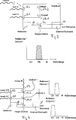
In
Vorteilhaft ist der Strahlteiler
Hierdurch kann am Eingang E1 ein Wechsel von einem Laser im IR-Bereich zu einem Laser im UV-Bereich erfolgen oder ein Laser in mehreren Betriebsarten betrieben werden, was den Einsatzbereich des Laser-Scanning-Mikroskopes erweitert, ohne dass ein zusätzlicher lichtschwächender Strahlteiler vorgesehen sein muss oder ein Austausch eines Strahlteilers erfolgen muss.As a result, a change from a laser in the IR range to a laser in the UV range can take place at the input E1 or a laser can be operated in several operating modes, which extends the field of application of the laser scanning microscope without providing an additional light-attenuating beam splitter or a replacement of a beam splitter must be done.
Am Eingang E2 wird hier ein Laser im sichtbaren Bereich über einen Spiegel
In
In
Auf diese Weise können sowohl ein IR-Laser über Eingang E3 sowie ein Laser im sichtbaren Bereich und ein Laser im UV-Bereich über E2 und E1 eingekoppelt werden und die verschiedenen Betriebsarten ohne Auswechslung von Lasern oder Strahlteilern mit den damit verbundenen Justierproblemen kann entfallen.In this way, both an IR laser via input E3 and a laser in the visible range and a laser in the UV range via E2 and E1 can be coupled and the various modes without replacement of lasers or beam splitters with the associated adjustment problems can be omitted.
Claims (3)
Priority Applications (2)
| Application Number | Priority Date | Filing Date | Title |
|---|---|---|---|
| DE19829953.2A DE19829953B4 (en) | 1998-07-04 | 1998-07-04 | Laser Scanning Microscope |
| US09/217,747 US6278555B1 (en) | 1998-07-04 | 1998-12-21 | Laser scanning microscope |
Applications Claiming Priority (1)
| Application Number | Priority Date | Filing Date | Title |
|---|---|---|---|
| DE19829953.2A DE19829953B4 (en) | 1998-07-04 | 1998-07-04 | Laser Scanning Microscope |
Publications (2)
| Publication Number | Publication Date |
|---|---|
| DE19829953A1 DE19829953A1 (en) | 2000-01-05 |
| DE19829953B4 true DE19829953B4 (en) | 2016-09-29 |
Family
ID=7872993
Family Applications (1)
| Application Number | Title | Priority Date | Filing Date |
|---|---|---|---|
| DE19829953.2A Expired - Lifetime DE19829953B4 (en) | 1998-07-04 | 1998-07-04 | Laser Scanning Microscope |
Country Status (2)
| Country | Link |
|---|---|
| US (1) | US6278555B1 (en) |
| DE (1) | DE19829953B4 (en) |
Families Citing this family (9)
| Publication number | Priority date | Publication date | Assignee | Title |
|---|---|---|---|---|
| US20050111089A1 (en) * | 1994-07-15 | 2005-05-26 | Baer Stephen C. | Superresolving microscopy apparatus |
| DE10233074B4 (en) * | 2002-07-19 | 2005-05-19 | Leica Microsystems Heidelberg Gmbh | Optical device for combining light beams and scanning microscope |
| JP4521155B2 (en) * | 2002-11-27 | 2010-08-11 | オリンパス株式会社 | Microscope image processing device |
| US20040200844A1 (en) * | 2003-04-11 | 2004-10-14 | David Watzke | Dual chamber salad container |
| JP2005030831A (en) * | 2003-07-09 | 2005-02-03 | Aisin Seiki Co Ltd | Light sorter for cell sorter |
| DE10350918B3 (en) * | 2003-10-31 | 2005-04-14 | Evotec Technologies Gmbh | Light transmission measuring device for chemical or biological sample with illumination light beam for overall illumination and stimulation light beam focused onto discrete measuring volumes |
| DE102009006729B4 (en) * | 2009-01-29 | 2021-12-23 | Carl Zeiss Microscopy Gmbh | Laser scanning microscope |
| US10634575B2 (en) * | 2016-03-31 | 2020-04-28 | Konica Minolta Laboratory U.S.A., Inc. | Laser scanning leak detection and visualization apparatus |
| EP3538941B1 (en) | 2016-11-10 | 2025-04-23 | The Trustees of Columbia University in the City of New York | Rapid high-resolution imaging methods for large samples |
Citations (6)
| Publication number | Priority date | Publication date | Assignee | Title |
|---|---|---|---|---|
| WO1986002730A1 (en) * | 1984-10-22 | 1986-05-09 | Hightech Network Sci Ab | A fluorescence imaging system |
| EP0470588A2 (en) * | 1990-08-08 | 1992-02-12 | GRUNDIG E.M.V. Elektro-Mechanische Versuchsanstalt Max Grundig holländ. Stiftung & Co. KG. | Projecting unit for large picture projection |
| DE4221063A1 (en) * | 1992-06-26 | 1994-01-05 | Thomas Dr Heiden | Optical system for incident light illumination fluorescence microscopy - splits light from source into several beams for independent modification before recombination |
| DE4330347A1 (en) * | 1993-09-08 | 1995-03-16 | Leica Lasertechnik | Device for the selection and detection of at least two spectral ranges of a light beam |
| DE29609959U1 (en) * | 1996-06-05 | 1996-10-10 | Zeiss Carl Jena Gmbh | Beam splitter for a confocal scanning microscope |
| US5798867A (en) * | 1997-02-04 | 1998-08-25 | Miyachi Technos Corporation | Laser beam-splitting apparatus |
Family Cites Families (9)
| Publication number | Priority date | Publication date | Assignee | Title |
|---|---|---|---|---|
| CA1163797A (en) * | 1982-01-14 | 1984-03-20 | Queen's University At Kingston | Laser interferometer |
| US5535052A (en) * | 1992-07-24 | 1996-07-09 | Carl-Zeiss-Stiftung | Laser microscope |
| JP3343276B2 (en) * | 1993-04-15 | 2002-11-11 | 興和株式会社 | Laser scanning optical microscope |
| US5952668A (en) * | 1994-07-15 | 1999-09-14 | Baer; Stephen C. | Resolution in microscopy and microlithography |
| US5874726A (en) * | 1995-10-10 | 1999-02-23 | Iowa State University Research Foundation | Probe-type near-field confocal having feedback for adjusting probe distance |
| DE19622359B4 (en) * | 1996-06-04 | 2007-11-22 | Carl Zeiss Jena Gmbh | Device for coupling the radiation of short-pulse lasers in a microscopic beam path |
| US6167173A (en) * | 1997-01-27 | 2000-12-26 | Carl Zeiss Jena Gmbh | Laser scanning microscope |
| US5910963A (en) * | 1997-04-08 | 1999-06-08 | Carl Zeiss Jena Gmbh | Laser resonator design with improved signal-to-noise level (S/N) at the output of a single-mode fiber-coupled multi-wavelength laser providing illumination for a laser scanning microscope |
| US5936728A (en) * | 1998-04-14 | 1999-08-10 | Noran Instruments, Inc. | Flash photolysis method and apparatus |
-
1998
- 1998-07-04 DE DE19829953.2A patent/DE19829953B4/en not_active Expired - Lifetime
- 1998-12-21 US US09/217,747 patent/US6278555B1/en not_active Expired - Lifetime
Patent Citations (6)
| Publication number | Priority date | Publication date | Assignee | Title |
|---|---|---|---|---|
| WO1986002730A1 (en) * | 1984-10-22 | 1986-05-09 | Hightech Network Sci Ab | A fluorescence imaging system |
| EP0470588A2 (en) * | 1990-08-08 | 1992-02-12 | GRUNDIG E.M.V. Elektro-Mechanische Versuchsanstalt Max Grundig holländ. Stiftung & Co. KG. | Projecting unit for large picture projection |
| DE4221063A1 (en) * | 1992-06-26 | 1994-01-05 | Thomas Dr Heiden | Optical system for incident light illumination fluorescence microscopy - splits light from source into several beams for independent modification before recombination |
| DE4330347A1 (en) * | 1993-09-08 | 1995-03-16 | Leica Lasertechnik | Device for the selection and detection of at least two spectral ranges of a light beam |
| DE29609959U1 (en) * | 1996-06-05 | 1996-10-10 | Zeiss Carl Jena Gmbh | Beam splitter for a confocal scanning microscope |
| US5798867A (en) * | 1997-02-04 | 1998-08-25 | Miyachi Technos Corporation | Laser beam-splitting apparatus |
Non-Patent Citations (1)
| Title |
|---|
| WINKLER,K., KNEBEL,W.: "Leica TCS 4D UV - Das Systemkonzept für die Multiparameter-Konfokalmikroskopie". Mitteilungen für Wissenschaft und Technik, Bd.XI, Nr.1, S.9-19, Juni 1995 * |
Also Published As
| Publication number | Publication date |
|---|---|
| DE19829953A1 (en) | 2000-01-05 |
| US6278555B1 (en) | 2001-08-21 |
Similar Documents
| Publication | Publication Date | Title |
|---|---|---|
| DE19758748C2 (en) | Laser Scanning Microscope | |
| DE19835072A1 (en) | Arrangement for illumination and/or detection in laser scanning microscope has selectively switchable micro-mirror arrangement in illumination and/or detection beam paths for wavelength selection | |
| DE102012203736A1 (en) | Scanning microscope with spectral detection | |
| EP1255105A1 (en) | Method for examining a sample and scanning microscope | |
| DE102013017468B4 (en) | Method for creating a microscope image and microscopy device | |
| WO2005029151A1 (en) | Scanning microscope with evanescent wave illumination | |
| EP1882970A1 (en) | Laser scanning microscope for fluorescence analysis | |
| DE10356826A1 (en) | scanning microscope | |
| DE10133017C2 (en) | Confocal microscope | |
| DE102004016253A1 (en) | Scanning microscope and method for scanning microscopic examination of a sample | |
| EP1678545B1 (en) | Microscope with evanescent sample illumination | |
| DE10233074B4 (en) | Optical device for combining light beams and scanning microscope | |
| DE102008062791A1 (en) | Microscope i.e. laser scanning microscope, for e.g. measuring fluorescence resonance energy transfer between fluorophores, has beam splitter including two dichroic layers arranged at angle with respect to each other | |
| DE10120424B4 (en) | Scanning microscope and decoupling element | |
| EP1281997B1 (en) | Scanning microscope | |
| EP1719998B1 (en) | Laser microdissection system | |
| WO2005031429A1 (en) | Objective for evanescent illumination and microscope | |
| DE19829953A1 (en) | Laser scanning microscope for scientific investigation of small objects | |
| DE102004029733B4 (en) | Scanning microscope and method for scanning microscopy | |
| WO2008043459A2 (en) | System for detection light division | |
| DE10031458A1 (en) | Scanning microscope has optical circulator between source(s), objective and detector(s) that feeds light from source(s) to objective associated with specimen, light from specimen to detector(s) | |
| DE19829954A1 (en) | Beam splitter for use in a laser scanning microscope | |
| DE10231475A1 (en) | Scanning microscope with optical component and optical component | |
| DE102004030208B3 (en) | Reflected-light microscope, has acousto-optical component in illumination beam path and observation beam path coupled to splitter-combiner | |
| EP3899631B1 (en) | Microscope and method for microscopic examination of large samples |
Legal Events
| Date | Code | Title | Description |
|---|---|---|---|
| OM8 | Search report available as to paragraph 43 lit. 1 sentence 1 patent law | ||
| 8110 | Request for examination paragraph 44 | ||
| R081 | Change of applicant/patentee |
Owner name: CARL ZEISS MICROSCOPY GMBH, DE Free format text: FORMER OWNER: CARL ZEISS JENA GMBH, 07745 JENA, DE Effective date: 20130206 |
|
| R016 | Response to examination communication | ||
| R018 | Grant decision by examination section/examining division | ||
| R020 | Patent grant now final | ||
| R071 | Expiry of right |