DE19903473B4 - Lance holder with multifunctional clamping head - Google Patents
Lance holder with multifunctional clamping head Download PDFInfo
- Publication number
- DE19903473B4 DE19903473B4 DE19903473A DE19903473A DE19903473B4 DE 19903473 B4 DE19903473 B4 DE 19903473B4 DE 19903473 A DE19903473 A DE 19903473A DE 19903473 A DE19903473 A DE 19903473A DE 19903473 B4 DE19903473 B4 DE 19903473B4
- Authority
- DE
- Germany
- Prior art keywords
- piston
- lance
- pressure
- holder according
- sleeve
- Prior art date
- Legal status (The legal status is an assumption and is not a legal conclusion. Google has not performed a legal analysis and makes no representation as to the accuracy of the status listed.)
- Expired - Lifetime
Links
- 238000007789 sealing Methods 0.000 claims abstract description 65
- 239000001301 oxygen Substances 0.000 claims abstract description 57
- 229910052760 oxygen Inorganic materials 0.000 claims abstract description 57
- QVGXLLKOCUKJST-UHFFFAOYSA-N atomic oxygen Chemical compound [O] QVGXLLKOCUKJST-UHFFFAOYSA-N 0.000 claims abstract description 56
- 230000006835 compression Effects 0.000 claims description 22
- 238000007906 compression Methods 0.000 claims description 22
- 230000008878 coupling Effects 0.000 claims description 5
- 238000010168 coupling process Methods 0.000 claims description 5
- 238000005859 coupling reaction Methods 0.000 claims description 5
- 210000003127 knee Anatomy 0.000 claims description 4
- 230000000903 blocking effect Effects 0.000 claims description 3
- 229920001084 poly(chloroprene) Polymers 0.000 claims description 2
- 238000011144 upstream manufacturing Methods 0.000 claims description 2
- MYMOFIZGZYHOMD-UHFFFAOYSA-N Dioxygen Chemical compound O=O MYMOFIZGZYHOMD-UHFFFAOYSA-N 0.000 description 18
- 229910001882 dioxygen Inorganic materials 0.000 description 18
- 239000002893 slag Substances 0.000 description 13
- 238000012549 training Methods 0.000 description 10
- 230000008901 benefit Effects 0.000 description 6
- 239000007789 gas Substances 0.000 description 4
- 238000000034 method Methods 0.000 description 4
- 238000003825 pressing Methods 0.000 description 4
- 230000008569 process Effects 0.000 description 4
- 230000009467 reduction Effects 0.000 description 4
- 230000006978 adaptation Effects 0.000 description 3
- 238000006073 displacement reaction Methods 0.000 description 3
- 230000000694 effects Effects 0.000 description 3
- 238000013461 design Methods 0.000 description 2
- 230000004308 accommodation Effects 0.000 description 1
- 230000009471 action Effects 0.000 description 1
- 238000013459 approach Methods 0.000 description 1
- 230000004888 barrier function Effects 0.000 description 1
- 230000009286 beneficial effect Effects 0.000 description 1
- 238000007664 blowing Methods 0.000 description 1
- 238000010276 construction Methods 0.000 description 1
- 230000006735 deficit Effects 0.000 description 1
- 238000011161 development Methods 0.000 description 1
- 238000005553 drilling Methods 0.000 description 1
- 239000000428 dust Substances 0.000 description 1
- 230000002349 favourable effect Effects 0.000 description 1
- 238000003780 insertion Methods 0.000 description 1
- 230000037431 insertion Effects 0.000 description 1
- 239000007788 liquid Substances 0.000 description 1
- 238000004519 manufacturing process Methods 0.000 description 1
- 239000000463 material Substances 0.000 description 1
- 150000002926 oxygen Chemical class 0.000 description 1
- 230000035515 penetration Effects 0.000 description 1
- 238000011084 recovery Methods 0.000 description 1
- 238000010992 reflux Methods 0.000 description 1
- 230000004044 response Effects 0.000 description 1
- 230000001960 triggered effect Effects 0.000 description 1
- 238000009423 ventilation Methods 0.000 description 1
Classifications
-
- C—CHEMISTRY; METALLURGY
- C21—METALLURGY OF IRON
- C21C—PROCESSING OF PIG-IRON, e.g. REFINING, MANUFACTURE OF WROUGHT-IRON OR STEEL; TREATMENT IN MOLTEN STATE OF FERROUS ALLOYS
- C21C5/00—Manufacture of carbon-steel, e.g. plain mild steel, medium carbon steel or cast steel or stainless steel
- C21C5/28—Manufacture of steel in the converter
- C21C5/42—Constructional features of converters
- C21C5/46—Details or accessories
- C21C5/4606—Lances or injectors
- C21C5/462—Means for handling, e.g. adjusting, changing, coupling
Landscapes
- Engineering & Computer Science (AREA)
- Chemical & Material Sciences (AREA)
- Manufacturing & Machinery (AREA)
- Materials Engineering (AREA)
- Metallurgy (AREA)
- Organic Chemistry (AREA)
- Quick-Acting Or Multi-Walled Pipe Joints (AREA)
Abstract
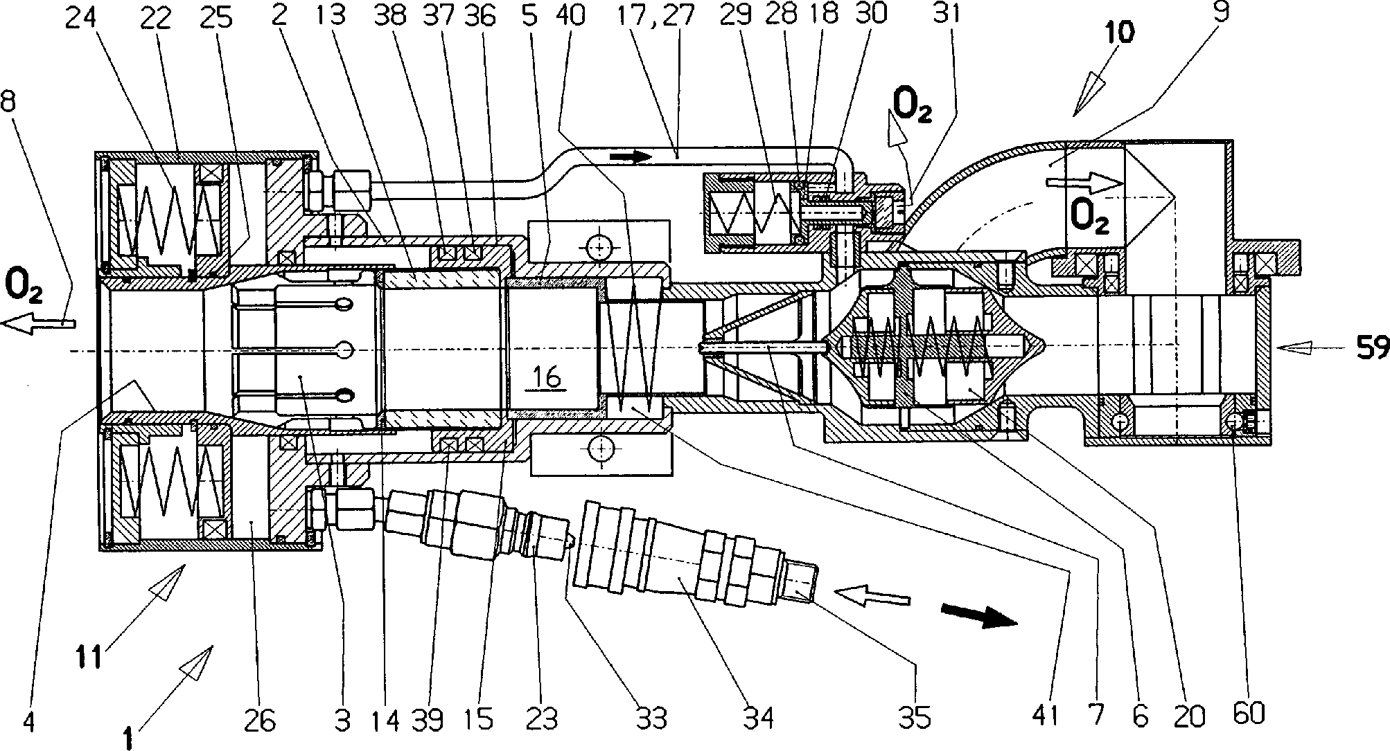
Lanzenhalter für Sauerstofflanzenrohre (12) mit einer Spannzange (3), die dem Durchmesser der Sauerstofflanzenrohre (12) anpassbar ist und einer Druckhülse (4), die am Halter (1) angeordnet und mit Hilfe einer Stelleinrichtung (11, 11', 11'') in Längsrichtung über die Spannzange (3) verschiebbar ausgebildet ist, wobei der Spannzange (3) eine verformbare, das Lanzenrohr (12) einklemmende Dichtungshülse (14) mit Dichtung (13) zugeordnet ist, dadurch gekennzeichnet, dass die Dichtungshülse (14) mit Dichtung (13) in einem begrenzt in Längsrichtung (8) des Halters (1) verschiebbaren und dabei auf die Dichtung (13) einwirkenden Druckkolben (15) angeordnet ist, der vom Druckmedium (O2) beaufschlagbar im Innenraum (16) des Haltergehäuses (2) positioniert ist und dass in Fließrichtung des Druckmediums (O2) hinter dem Druckkolben (15) ein den Innenraum (16) des Haltergehäuses (2) mit der Atmosphäre verbindbarer Bypass (17) mit Sicherheitssperrkolben (18, 68) vorgesehen ist, der über die Stelleinrichtung (11) entsperrbar ausgebildet ist.Lance holder for oxygen lance tubes (12) with a collet (3) which is adaptable to the diameter of the oxygen lance tubes (12) and a pressure sleeve (4) arranged on the holder (1) and by means of an adjusting device (11, 11 ', 11'') in the longitudinal direction on the collet (3) is displaceably formed, wherein the collet (3) is associated with a deformable, the lance tube (12) clamping sleeve (14) with seal (13), characterized in that the sealing sleeve (14) with seal (13) in a limited longitudinal direction (8) of the holder (1) displaceable and thereby on the seal (13) acting pressure piston (15) is arranged, of the pressure medium (O 2 ) acted upon in the interior (16) of the holder housing (2) is positioned and that in the flow direction of the pressure medium (O 2 ) behind the pressure piston (15) a the interior (16) of the holder housing (2) connectable to the atmosphere by-pass (17) with safety lock piston (18, 68) is provided the ü Is formed unlockable via the adjusting device (11).
Description
Die Erfindung betrifft einen Lanzenhalter für Sauerstofflanzenrohre mit einer Spannzange, die dem Durchmesser der Sauerstofflanzenrohre anpassbar ist und einer Druckhülse, die am Halter angeordnet und mit Hilfe einer Stelleinrichtung in Längsrichtung über die Spannzange verschiebbar ausgebildet ist, wobei der Spannzange eine verformbare, das Lanzenrohr einklemmende Dichtungshülse mit Dichtung zugeordnet ist.The The invention relates to a lance holder for oxygen lance tubes a collet, the diameter of the oxygen lance tubes is customizable and a pressure sleeve, arranged on the holder and with the aid of an adjusting device in the longitudinal direction over the Collet is designed to be displaceable, wherein the collet a deformable, the lance tube clamping sleeve with Associated with seal.
Lanzen mit einem Spannkopf und einer darüber schiebbaren Druckhülse dienen dazu, die zum Frischen benötigte Lanze sicher zu halten und zum anderen, beispielsweise bei einer Beendigung oder Unterbrechung des Blasvorganges sicherzustellen, dass die mit dem Lazenhalter hantierenden Arbeiter nicht gefährdet sind. Lanzenhalter mit einer Schlackenrücklaufsicherung sind der EP-B1-0 372 098 zu entnehmen. Hier wird die Druckhülse mit Hilfe eines Kniehebels über die Spannzange geschoben, um das Lanzenrohr zu fixieren. Hinter der Spannzange ist eine Dichtung angeordnet, die beim Verschieben der Spannzange verquetscht wird, um so das Lanzenrohr dicht zu umschließen. Ein derartiger Lanzenhalter bzw. seine Spannzange passt sich an unterschiedliche Rohrdurchmesser zum Teil an, wobei die zum Verspannen notwendige Kraft entsprechend veränderlich ist. Dies und die notwendige Kraftaufwendung führt dazu, dass der Kniehebel oft mit Gewalt zurückgedrückt oder geschlagen wird, sodass es zu Beschädigungen an den Lanzenhaltern kommt. Die nicht mehr genaue Fixierung bzw. Sicherung der Sauerstofflanzenrohre ist die Folge. Auch die DE-PS-195 47 885 zeigt einen einem Lanzenmanipulator zugeordneten Lanzenhalter, bei dem aber Handarbeit zum Verspannen der Sauerstofflanzenrohre weitgehend entfällt, weil die Druckhülse über einen Spannkolben verfügt, der dafür sorgt, dass eine entsprechend starke Feder dann für eine sichere Halterung der Lanzenrohre sorgt, wenn der Spannkolben entlastet ist. Soll ein Rohrende entfernt und ein neues Sauerstofflanzenrohr eingeführt werden, wird Druckluft auf den Spannkolben gegeben, sodass dieser gegen die Kraft der Druckfeder verschoben wird und dabei die Spannzange entlastet, sodass entsprechende Manipulationen möglich werden. Ein derartiger Lanzenhalter verfügt über erhebliche Vortei le, kann aber in Extremsituationen nicht vermeiden, dass Gefährdungen des Personals eintreten. Eine solche Gefährdung ist beispielsweise dann gegeben, wenn das Sauerstofflanzenrohr vorne verstopft ist und zwar in der Regel mit Schlacke. Beim Aufgeben von Sauerstoff kann dieser dann die Sauerstofflanze dann verlassen, sodass sich ein gefährlich hoher Druck im Lanzenhalter und den damit verbundenen Teilen aufbaut. Wird dann die Spannzange entlastet, kommt es zu einem gefährlichen Heraufliegen des Sauerstofflanzenrohres oder aber auch einem Zurückschnellen des Lanzenhalters.lances Serve with a chuck and a push-on pressure sleeve in addition, needed for fresh Lance to keep safe and the other, for example, at a Stop or interrupt the blowing process to ensure that The workers handling the Lazenhalter are not endangered. Lance holders with a slag return protection are EP-B1-0 372 098 to remove. Here is the pressure sleeve with the help of a toggle over the Collet pushed to fix the lance tube. Behind the Collet is a seal arranged when moving the Collet is squeezed so tightly enclose the lance tube. One Such lance holder or his collet adapts to different Pipe diameter partly, with the necessary for bracing Force correspondingly changeable is. This and the necessary expenditure of energy leads to the toggle lever often pushed back by force or is beaten, causing damage to the lance holders comes. The no longer accurate fixing or securing of the oxygen lance pipes is the consequence. The DE-PS 195 47 885 shows a lance manipulator associated lance holder, but in which manual labor for bracing the oxygen lance tubes largely eliminated, because the pressure sleeve over a Tensioning piston has, the one for it ensures that a correspondingly strong spring then for a secure mount the lance tubes provide when the tensioning piston is relieved. Should a pipe end is removed and a new oxygen lance pipe is introduced Compressed air is applied to the clamping piston, so that this against the force the compression spring is displaced, thereby relieving the collet, so that appropriate manipulations are possible. Such a Lance holder has considerable Advantages, but can not avoid hazards in extreme situations of the staff. Such a risk, for example, then given when the oxygen lance tube is clogged at the front and that usually with slag. When giving up oxygen this can then leave the oxygen lance, so that a dangerously high Pressure builds up in the lance holder and the associated parts. If then the collet relieved, it comes to a dangerous Lying up the oxygen lance pipe or even a snap back of the lance holder.
Der Erfindung liegt daher die Aufgabe zugrunde, einen Lanzenhalter zu schaffen, der auf einfache und handhabungssichere Weise mit dem Lanzenrohr zu verbinden und auch bei verstopftem Lanzenrohr und Druckbeaufschlagung vom Lanzenrohr wieder zu entkoppeln ist.Of the Invention is therefore based on the object to a lance holder create a simple and manageable way with the Lance tube to connect and even with clogged lance tube and Compressing the lance pipe is to decouple again.
Die Aufgabe wird gemäß der Erfindung dadurch gelöst, dass die Dichtungshülse mit Dichtung in einem begrenzt in Längsrichtung des Halters verschiebbaren und dabei auf die Dichtung einwirkenden Druckkolben angeordnet ist, der vom Druckmedium (O2) beaufschlagbar im Innenraum positioniert ist und dass in Fließrichtung des Druckmediums (O2) hinter dem Druckkolben ein den Innenraum des Haltergehäuses mit der Atmosphäre verbindbarer Bypass mit Sicherheitssperrkolben vorgesehen ist, der über die Stelleinrichtung entsperrbar ausgebildet ist.The object is achieved according to the invention in that the sealing sleeve is arranged with a seal in a longitudinally displaceable in the longitudinal direction of the holder and thereby acting on the seal pressure piston, which is positioned by the pressure medium (O 2 ) acted upon in the interior and that in the flow direction of the pressure medium (O 2 ) is provided behind the pressure piston a the interior of the holder housing with the atmosphere connectable bypass with safety lock piston, which is designed to be unlockable via the adjusting device.
Mit Hilfe eines derart aufgebauten Lanzenhalters ist es möglich, bei verstopftem Sauerstofflanzenrohr, vor allem durch Schlacke verstopftem Lanzenrohr den Innenraum des Lanzenhalters so zwangsdruck zu entlasten, dass danach das Lanzenrohr entnommen und durch ein neues ersetzt werden kann, ohne dass eine Gefährdung auftritt. Der Innenraum des Lanzenhalters ist dazu über einen Bypass mit der Atmosphäre verbunden, wobei der im Bypass angeordnete Sicherheitssperrkolben über die Stelleinrichtung, die die Druckhülse über die Spannzange schiebt bzw. zurückschiebt, entsperrt wird. Dies bedeuted, dass beim Zurückschieben der Druckhülse von der Spannzange automatisch der Sicherheitssperrkolben geöffnet wird, sodass der im Innenraum unter Druck anstehende Sauerstoff Abströmen kann. Der die Dichtungshülse beeinflussende Druckkolben wird dabei durch den Sauerstoff so lange belastet und fixiert damit das Lanzen rohr vorteilhaft, bis der Druckaufbau im Innenraum entsprechend weit reduziert ist. Gleichzeitig wirkt auch während des normalen Betriebes ein solcher Druckkolben vorteilhaft zusätzlich das Lanzenrohr arretierend. Damit ist eine die Halterung des Lanzenrohres zusätzlich sichernder Lanzenhalter geschaffen, der auch in Extremsituationen eine sichere Handhabung ermöglicht.With Help of such a constructed lance holder, it is possible at clogged oxygen lance tube, especially clogged by slag Lance tube to relieve the interior of the lance holder so forcing pressure that then removed the lance tube and replaced by a new one can be without putting a hazard occurs. The interior of the lance holder is about a Bypass with the atmosphere connected, wherein the arranged in the bypass safety locking piston on the Adjusting device, the pressure sleeve on the Collet pushes or pushes back, is unlocked. This means that when pushing back the pressure sleeve of the collet automatically opens the safety lock plunger, so that the oxygen in the interior under pressure may flow out. Of the the sealing sleeve influencing pressure piston is doing so long by the oxygen loaded and fixed so that the lance tube advantageous until the pressure build-up in the interior is correspondingly far reduced. At the same time works even while the normal operation of such a pressure piston advantageous additionally Lance tube arresting. This is a the holder of the lance tube additionally Securing lance holder is created, even in extreme situations enables safe handling.
Nach einer zweckmäßigen Ausbildung der Erfindung ist vorgesehen, dass dem Druckkolben ein Sauerstoffrückschlagventil mit integrierter Schlackenrücklaufsicherung vorgeordnet ist. Dieses Sauerstoffrückschlagventil schließt den Innenraum des Lanzenhalters ab und sorgt dafür, dass bei angesprochener Schlackenrücklaufsicherung Sauerstoff in den Lanzenhalter nicht nachströmen kann.To appropriate training The invention provides that the pressure piston an oxygen check valve with integrated slag return safety device is upstream. This oxygen check valve closes the interior of the lance holder and ensures that when addressed Slag backflow protection Oxygen in the lance holder can not flow.
Weiter vorne ist bereits darauf hingewiesen worden, dass es für die Betätigung der Lanzenhalterung mehrere Lösungen gibt, d. h. die Stelleinrichtung kann unterschiedlich aufgebaut sein, dennoch aber mit entsprechendem Zuschnitt die Aufgabe lösen. Nach einer zweckmäßigen Ausbildung ist vorgesehen, dass die Druckhülse wie an sich bekannt zweiteilig ausgebildet ist, ein Gehäuse mit Druckluftanschluss und mit einem gegen die Kraft einer Spannfeder die Spannzange entlastenden Spannkolben aufweist und dass der dem Spannkolben zugeordnete Zylinderraum über eine als Bypass dienende Zuführleitung mit dem Sicherheitssperrkolben verbunden ist. Die Betätigung des Lanzenhalters erfolgt wie bekannt durch Beaufschlagen des Spannkolbens mit Druckluft. Der Spannkolben verschiebt sich gegen die Kraft der Spannfeder und entlastet damit die Spannzange, sodass das im Lanzenhalter befindliche Lanzenrohr entfernt und durch ein neues ersetzt werden kann. Hat sich nun beispielsweise durch das Verstopfen des Lanzenrohres ein Druck im Lanzenhalter aufgebaut, so wird dieser zwangsentlastet und abgebaut, weil die Druckluft durch den Zylinderraum und die Zuführleitung in den Sicherheitssperrkolben strömt und diesen öffnet. Damit ist die Verbindung zwischen Atmosphäre und Innenraum des Lanzhalters hergestellt und der gefährliche Überdruck im Lanzenhalterinnenraum kann abgebaut werden.Further It has already been pointed out above that it is necessary for the operation of the Lance holder several solutions there, d. H. the adjusting device can be constructed differently be, but still solve the problem with the appropriate cut. To appropriate training is provided that the pressure sleeve as is known in two parts, a housing with Compressed air connection and with one against the force of a tension spring has the collet relieving clamping piston and that the Cylinder chamber associated with clamping piston via a feed line serving as a bypass connected to the safety lock piston. The operation of the Lance holder takes place as known by applying the tensioning piston Compressed air. The tensioning piston shifts against the force of the tension spring and thus relieves the collet, so that in the lance holder located Lance tube can be removed and replaced with a new one. Has Now, for example, by the clogging of the lance tube Pressure built up in the lance holder, this is forcibly relieved and degraded, because the compressed air through the cylinder chamber and the feed flows into the safety lock piston and opens this. In order to is the connection between atmosphere and interior of the lance holder produced and the dangerous overpressure in the lance holder interior can be dismantled.
Ein sicheres Ansprechen des Sicherheitssperrkolbens wird dadurch erreicht, dass die Zuführleitung den Schließkolben des Sicherheitssperrkolbens beeinflussend ange schlossen ist, wobei der Schließkolben über eine Druckfeder in der Schließstellung gehalten ist. Die durch die Zuführleitung zuströmende Druckluft verschiebt den Schließkolben gegen die Kraft der Druckfeder und bringt ihn damit aus der Schließstellung. Ein gefährlicher Überdruck im Lanzengehäuse kann damit abgebaut werden. Beim Normalbetrieb des Lanzenhalters bleibt der Sicherheitssperrkolben zwangsweise so lange geöffnet, bis die Druckluftzufuhr gestoppt und der Spannkolben entlastet wird. Damit fehlt in der Zuführleitung der notwendige Druck und die Druckfeder kann den Schließkolben des Sicherheitssperrkolbens wieder schließen.One Safe response of the safety lock piston is achieved by that the supply line the closing piston the safety lock piston influencing is connected, wherein the closing piston over a Compression spring in the closed position is held. The through the feed line incoming Compressed air displaces the closing piston the force of the compression spring, bringing him out of the closed position. A dangerous overpressure in the lance housing can be reduced with it. During normal operation of the lance holder the safety lock piston remains forced to remain open until the compressed air supply is stopped and the tensioning piston is relieved. This is missing in the supply of the necessary pressure and the compression spring can be the closing piston Close the safety lock piston again.
Eine einfache und schnelle Handhabung eines derartigen Lanzenhalters wird dadurch verbessert, dass der Druckluftanschluss am Gehäuse über einen Kupplungsstift verfügt, der über eine aufgesteckte Absperrkupplung beeinflussbar ausgebildet ist. Solange die Absperrkupplung auf den Kupplungsstift aufgeschoben ist, kann Druckluftzugeführt werden. Soll die Druckluftzufuhr beendet werden, wird die Absperrkupplung einfach abgezogen und damit der Spannkolben wieder entlastet. Die Absperrkupplung verschließt sich automatisch, sodass Druckluft nicht mehr nachströmt.A simple and quick handling of such a lance holder is improved by the compressed air connection on the housing via a Coupling pin features, the over an attached shut-off is influenced influenced. As long as the shut-off clutch is pushed onto the coupling pin is compressed air can be supplied become. If the compressed air supply is terminated, the shut-off is simply pulled off and thus relieved the tensioning piston again. The Locking coupling closes automatically, so that compressed air no longer flows.
Die weiter vorne erwähnte Dichtungshülse, die vom Druckkolben umgeben und damit über diesen mit verquetscht wird, sorgt dafür, dass das Lanzenrohr zusätzlich abgedichtet und vor allem arretiert wird und auch dann durch diese Arretierung noch gehalten wird, wenn zum Abbau eines Sauerstoffüberdruckes im Innenraum die Spannzange entlastet werden muss. Abweichend vom Stand der Technik wird die Dichtungshülse durch die besondere Ausbildung von beiden Seiten her verquetscht, sodass eine absolut sichere Halterung bzw. Abdichtung gewährleistet ist. Die Dichtungshülse wird nämlich einmal durch den Druckkolben und zum anderen durch die Spannzange belastet. Beim Druckabbau im Innenraum, bei dem die Spannzange bereits entlastet ist, sorgt der Druckkolben für eine Fixierung des Lanzenrohres solange, bis der Druck im Innenraum eine ungefährliche Größenordnung erreicht hat.The mentioned earlier Sealing sleeve, the Surrounded by the pressure piston and thus squeezed over this with will, make sure that the lance tube in addition sealed and, above all, arrested and then by this Locking is still held when to reduce an oxygen overpressure in the interior of the collet must be relieved. Deviating from Prior art, the sealing sleeve by the special training Squeezed from both sides, so an absolutely secure mount or sealing guaranteed is. The sealing sleeve that is once through the plunger and the other through the collet loaded. When pressure reduction in the interior, where the collet already is relieved, the pressure piston ensures a fixation of the lance tube until the pressure in the interior has reached a harmless magnitude.
Der Druckkolben soll wie erwähnt sich in Richtung Spannzange verschieben und dabei die Neopren-Dichtung bzw. Dichtungshülse entsprechend belasten. Er wird dabei gegenüber der Wandung des Innenraums abgesichert, indem der die Dichtungshülse aufnehmende Druckkolben auf der Außenwand eine Nut mit einer O-Ringdichtung aufweist. Diese O-Ringdichtung bzw. die O-Ringdichtungen erlauben ein Verschieben des Druckkolbens, ohne dass ihre Dichtwirkung dadurch beeinträchtigt wird, sodass sie sich für den hier beschriebenen Einsatzfall besonders gut eignen.Of the Pressure piston should as mentioned to move towards the collet while the neoprene seal or sealing sleeve charge accordingly. He will be facing the wall of the interior secured by the sealing sleeve receiving the pressure piston on the outside wall has a groove with an O-ring seal. This O-ring seal or the O-ring seals allow a displacement of the pressure piston, without that their sealing effect is affected by it, so they themselves for the Particularly suitable here described application.
Neben der Pneumatikausführung des Lanzenhalters ist auch eine mechanische Ausführung möglich, die gemäß der Erfindung eine Druckhülse aufweist, die mit Hilfe eines Kniehebels auf die Spannzange schiebbar bzw. von ihr herunterschiebbar ausgebildet ist, wobei der die Dichtungshülse aufnehmende Druckkolben auf Bypasskolben des Sicherheitssperrkolbens einwirkend angeordnet ist und bei der die Bypasskolben mit dem Bypass sperrendem Dichtelement über eine die Ventilöffnungsposition sicherende Druckfeder belastet sind. Mit Hilfe einer derartigen Konstruktion ist es auch bei einer solch mechanischen Ausbildung möglich, beispielsweise bei verstopftem Lanzenrohr das Lanzenrohr zu fixieren und gleichzeitig den Innenraum Druck zu entlasten. Dies erreicht man dadurch, dass der Kniehebel zunächst einmal die Druckhülse von der Spannzange herabschiebt und dabei gleichzeitig durch die Entlastung der Spannzange dafür sorgt, dass der die Dichtungshülse aufnehmende Druckkolben nachschiebt, die Dichtungshülse verquetscht und das Lanzenrohr fixiert. In den vom zurückweichenden Druckkolben freien Raum schieben Bypasskolben des Sicherheitsventils ein, die dabei gleichzeitig den Bypass zwischen Innenraum und Atmosphäre freigeben, sodass der Sauerstoffüberdruck im Innenraum abgebaut werden kann. Ist dies erfolgt, sorgt der Druckkolben dafür, dass die Bypasskolben wieder in das sperrende Dichtelement geschoben werden, sodass das Dichtelement wieder entsprechend den Ausgang verschließt. Vorteilhaft hierbei ist, dass überraschend auch eine mechanische Lösung möglich ist, die ausreichend leichtgängig bleibt und dennoch dafür sorgt, dass in solchen extremen Situationen das Lanzenrohr so lange fixiert bleibt, bis es gefahrlos aus dem Lanzenhalter entnommen werden kann.In addition to the pneumatic version of the lance holder and a mechanical design is possible, which according to the invention comprises a pressure sleeve which is slidably mounted by means of a toggle lever on the collet or pushed down by her, wherein the sealing sleeve receiving pressure piston is arranged acting on bypass piston of the safety lock piston and in which the bypass pistons are loaded with the bypass-locking sealing element via a compression spring securing the valve opening position. With such a construction, it is also possible in such a mechanical training, for example, to fix the lance tube in clogged lance tube and at the same time to relieve the pressure inside. This is achieved by the fact that the toggle initially pushes down the pressure sleeve of the collet and at the same time ensures by relieving the collet that the sealing sleeve receiving pressure piston nachschiebt, squeezes the sealing sleeve and fixes the lance tube. Bypass pistons of the safety valve push into the free space from the receding pressure piston, simultaneously releasing the bypass between the interior and the atmosphere, so that the oxygen overpressure in the interior can be reduced. Once this is done, the pressure piston ensures that the bypass piston back in the locking sealing element are pushed, so that the sealing element closes again according to the output. The advantage here is that surprisingly, a mechanical solution is possible, which remains sufficiently smooth and yet ensures that in such extreme situations, the lance tube remains fixed until it can be safely removed from the lance holder.
Eine günstige Unterbringung der Druckfeder, über die das Dichtelement gesperrt wird bzw. sperrend wirkt, ist die, bei der die Druckfeder den Bypasskolben umgebend und sich einerseits gegen die Rückseite des Druckkolbens und andererseits gegen die Ringwandung von Steckbohrungen für die Bypasskolben vor dem Dichtelement abstützend angeordnet ist. Die Druckfeder kann damit den öffnungsvorgang vorteilhaft unterstützen, während das Dichtelement automatisch wirkt, wenn der Bypasskolben über den Druckkolben in die Schließstellung gedrückt wird. Auch dann, wenn einer oder mehrere der Bypasskolben geringfügig Verhaken sollten, sorgt diese Druckfeder dafür, dass in einem solchen Falle der Sauerstoff entsprechend durch das Dichtelement Abströmen kann.A favorable Accommodation of compression spring, over the sealing element is blocked or has a blocking effect, is the, in which the compression spring surrounding the bypass piston and on the one hand against the back the pressure piston and on the other hand against the annular wall of plug bores for the Bypass piston is arranged in front of the sealing element supporting. The compression spring can thus the opening process beneficial support, while the sealing element acts automatically when the bypass piston over the Pressure piston in the closed position is pressed. Even if one or more of the bypass pistons get caught slightly should, this compression spring ensures that in such a case the oxygen can flow out through the sealing element accordingly.
Gemäß einer zweckmäßigen Ausbildung ist vorgesehen, dass das Dichtelement als ein gegen den Bypasskolben abdichtender Dichtring ausgebildet ist. Hierdurch wird erreicht, dass bereits bei geringem Verschiebeweg der Bypasskolben den Sicherheitssperrkolben so weit geöffnet hat, dass bereits ein Druckabbau erfolgt.According to one appropriate training is provided that the sealing element as a against the bypass piston sealing gasket is formed. This will achieve that even with a small displacement of the bypass piston the safety lock piston opened so far has that already a pressure reduction takes place.
Um zu verhindern, dass bei dem recht rauhen Betrieb Schmutz in den Bereich des Dichtelementes eindringt, ist vorgesehen, dass das Dichtelement einer Auslassöffnung zugeordnet ist, in der eine Schmutzsicherung angeordnet ist. Diese Schmutzsicherung erlaubt das Ausströmen von Sauerstoff, insbesondere wenn dieser mit Überdruck ansteht, verhindert aber, dass Staub oder gar gröbere Teile in die Auslassöffnung eindringen können.Around To prevent dirt from getting in the rough place of operation Area of the sealing element penetrates, it is provided that the sealing element an outlet opening is assigned, in which a pollution control is arranged. These Dirt control allows the outflow of oxygen, in particular if this with overpressure is present, but prevents dust or even coarser parts from entering the outlet opening can.
Das Abströmen des Sauerstoffs aus dem Innenraum des Lanzenhalters kann bei der mechanischen Lösung vorteilhaft auf kürzestem Weg vorgenommen werden, indem der Bypass von Radialbohrungen gebildet ist, die den Innenraum in Höhe der Pufferhülse mit den Steckbohrungen verbinden, in denen die Bypasskolben verschieblich angeordnet sind. Der Sauerstoff steht in entsprechender Menge somit immer in diesem Bereich an und sorgt dafür, dass der Druckkolben entsprechend verspannend auf die Druckhülse einwirkt. Zumindest wird diese Funktion unterstützt. Andererseits aber kann der Sauerstoff auf kürzestem Wege Abströmen, wenn der beschriebene Problemfall eintreten sollte, indem der Sauerstoff durch das Lanzenrohr nicht Abströmen kann.The outflow of the oxygen from the interior of the lance holder can at the mechanical solution advantageous to the shortest Path are made by forming the bypass of radial bores is the height of the interior the buffer sleeve connect with the plug holes in which the bypass piston displaceable are arranged. The oxygen is in an appropriate amount thus always in this area and ensures that the pressure piston accordingly tensioning on the pressure sleeve acts. At a minimum, this feature is supported. On the other hand, though the oxygen on the shortest Ways to escape, if the problem described should occur by the oxygen do not escape through the lance tube can.
Weiter vorne ist bereits erwähnt worden, dass durch geschickte Ausführung die Sperrwirkung des Druckkolbens unterstützt werden kann, wozu es vorteilhaft ist, wenn die Steckbohrungen und die Bypasskolben den Sauerstoff bedingt durchlassend ausgebildet sind und/oder dass Parallelkanäle vorgesehen sind. Die Steckbohrungen bzw. vor allem durch die Parallelkanäle kann der Sauerstoff auch beim Normalbetrieb so unter den Druckkolben geführt werden, dass damit eine sichere Halterung des Lanzenrohres unterstützt wird.Further the front is already mentioned that by skillful execution the blocking effect of Plunger supported can be what it is advantageous if the plug holes and the bypass piston formed the oxygen conditionally permeable are and / or that are parallel channels are provided. The plug holes or especially by the parallel channels can the oxygen also in normal operation so under the pressure piston guided be that a secure support of the lance tube is supported.
Bei der weiter oben beschriebenen Lösung ist es von Vorteil, wenn der Druckkolben die Dichtungshülse und die Spannzange einfassend ausgebildet ist. Damit wird die Beeinflussung der Dichtungshülse weiter optimiert, um die Fixierung des Lanzenrohres zu sichern. Die Spannzange selbst wird gezielt im Druckkolben geführt, um auch auf ihre Weise zur "Verformung" der Dichtungshülse beizutragen und so das Lanzenrohr sicher zu fixieren und auch abzudichten.at the solution described above It is advantageous if the pressure piston the sealing sleeve and the collet is formed enclosing. This is the influence the sealing sleeve further optimized to secure the fixation of the lance tube. The collet itself is specifically guided in the pressure piston to also contribute in their way to the "deformation" of the sealing sleeve and to securely fix and seal the lance tube.
Der für die beschriebene Tätigkeit benötigte Sauerstoff wird über einen Schlauch dem Lanzenhalter zugeführt, wobei dieser Schlauch aufgrund des herrschenden Druckes und seiner speziellen Ausbildung nur mit entsprechendem Kraftaufwand zu manipulieren ist. Da er mit dem Lanzenhalter verbunden ist, kann er dessen Beweglichkeit einschränken. Dies gilt natürlich insbesondere dann, wenn aufgrund eines verstopften Lanzenrohres Überdruck im Lanzenhalter und natürlich auch im Schlauchanschluss bzw. im Sauerstofflanzenschlauch ansteht. Um diese Probleme zu vermeiden, sieht die Erfindung vor, dass dem Sauerstofflanzenschlauch ein Schwenkgelenk mit Kugellagerführung zugeordnet ist. Dieses Schwenkgelenk kann jeweils in eine Lage gebracht werden, die die Beeinträchtigung der Bewegungsfreiheit des Lanzenhalters vermeidet, weil der Sauerstofflanzenschlauch in einer entsprechenden Richtung gehalten wird.Of the for the described activity needed oxygen will over a hose supplied to the lance holder, said hose due to the pressure and his special training only with appropriate force manipulation is. Since he is with the lance holder is connected, he can limit his mobility. this applies Naturally especially when due to a clogged lance tube overpressure in the lance holder and of course also present in the hose connection or in the oxygen lance hose. To avoid these problems, the invention provides that the Oxygen lance hose assigned a swivel joint with ball bearing guide is. This swivel joint can each be brought into a position the impairment the freedom of movement of the lance holder avoids because of the oxygen lance tube is held in a corresponding direction.
Eine quasi automatische Anpassung wird dadurch erreicht, dass das Schwenkgelenk einen sich dem aktuellen Arbeitswinkel des Sauerstofflanzenschlauches selbsttätig anpassenden Anschlussstutzen aufweist. Dieser Anschlussstutzen schwenkt um das Schwenkgelenk jeweils so, dass der Sauerstofflanzenschlauch jeweils oprimal gehalten ist, d. h. so dass er die Bewegungsfreiheit des Lanzenhalters nicht beeinträchtigt, selbst aber auch nicht im Bogen bzw. gar abgeknickt geführt ist. Insgesamt gesehen ergibt sich damit eine wesentlich bessere Handhabungsmöglichkeit für einen derartigen Lan zenhalter, gleich ob er einem Lanzenmanipulator zugeordnet ist oder aber von den Arbeitern direkt gehandhabt wird.A virtually automatic adaptation is achieved by the fact that the swivel joint the actual working angle of the oxygen lance tube automatic having matching connecting pieces. This connection swivels the pivot joint in each case so that the oxygen lance tube each is kept oprimal, d. H. allowing him freedom of movement of the lance holder is not affected, but also not guided in a bow or even bent. Overall, this results in a much better handling option for one such Lan zenhalter, whether he assigned a lance manipulator or handled directly by the workers.
Eine vom Aufbau her vorteilhaft einfache Ausführung des Lanzenhalters sieht vor, dass die Druckhülse über den Kniehebel auf der Spannzange verschiebbar ausgebildet ist, dass der Druckkolben über eine in einem mit dem Innenraum verbundenen Federraum angeordnete Druckfeder in Richtung Öffnung der Druckhülse belastet ist und dass der Federraum über eine Steckbohrung mit den Bypass verbunden ist, der dicht vor der als Sicherheitssperrkolben dienenden O-Ringdichtung endend ausgebildet ist. Dadurch entfallen vorteilhaft aufwendige Ventile, entsprechende gesonderte Bypässe und andere den Aufbau des Lanzenhalters komplizierende Teile, weil gemäß der Erfindung nun der eigentliche Druckkolben gleichzeitig auch als eine Art Ventil ausgebildet ist. Der eventuell noch im Lanzenhalter anstehende Druck des Sauerstoffgases sorgt dafür, dass der Druckkolben mit der innen liegenden Dichtungshülse und Dichtung so weit verschoben wird, dass die vorgesehene O-Ringdichtung einen Durchtritt des anstehenden Sauerstoffgases in Richtung auf die Druckhülse ermöglicht. Dabei kann dann das unter Druck anstehende Sauerstoffgas an der Spannzange vorbei in die Atmosphäre abgeführt werden. Vorteilhaft ist dabei insbesondere, dass das noch unter Druck anstehende Sauerstoffgas nicht quer aus dem Lanzenhalter abgeführt wird, sondern vor Kopf, sodass eine Gefährdung des Bedienungspersonals absolut mit Sicherheit ausgeschlossen werden kann. Das Sauerstoffgas tritt nämlich vor Kopf der Druckhülse aus und zwar so, dass die Bedienung überhaupt nicht im Bereich des austretenden Gases stehen oder tätig sein kann. Zur Unterstützung des Druckkolbens dient dabei die im Federraum angeordnete Druckfeder, die dafür sorgt, dass auch schon bei geringeren Mengen an Sauerstoffgas dieses so abgeleitet wird, dass eine Gefährdung von ihm nicht mehr ausgehen kann. Dies erfolgt dadurch, dass die Druckfeder sicherstellt, dass der Druckkolben sich verschiebt und dabei den O-Ring so weit verschiebt, dass das Sauerstoffgas daran vorbeiströmen kann. Dabei bleibt der Vorteil erhalten, dass bei eingeschobenem Sauerstofflanzenrohr dieses einmal über die Spannzange festgelegt wird und zum anderen über den durch das Sauerstoffgas belasteten Druckkolben mit der entsprechend verformten Dichtung in der Dichtungshülse.A structurally advantageous simple design of the lance holder sees before that the pressure sleeve over the Toggle lever is formed on the collet displaceable, that the pressure piston over one arranged in a spring chamber connected to the interior Compression spring in the direction of the opening the pressure sleeve is loaded and that the spring chamber via a plug hole with the Bypass is connected, which close in front of as a safety lock piston serving O-ring seal is formed ending. This accounts advantageous complex valves, corresponding separate bypasses and other parts complicating the structure of the lance holder, because according to the invention now the actual pressure piston at the same time as a kind of valve is trained. The pressure that may still be present in the lance holder the oxygen gas ensures that the pressure piston with the inner sealing sleeve and Seal is moved so far that the intended O-ring seal a passage of the pending oxygen gas in the direction of the pressure sleeve allows. In this case, then the pressurized oxygen gas at the Collet passing in the atmosphere dissipated become. It is advantageous in particular that even under pressure pending oxygen gas is not removed transversely from the lance holder, but in the head, so a threat to the operator can absolutely be ruled out with certainty. The oxygen gas namely occurs in front of the head of the pressure sleeve in such a way that the service at all in the area of emerging gas or active can be. For support the pressure piston is used in the spring chamber arranged compression spring, the one for that ensures that even with lower amounts of oxygen gas this is derived so that a threat from him no longer go out can. This is done by the compression spring ensures that the pressure piston moves and thereby the O-ring shifts so far that the oxygen gas can flow past it. The remains Obtained advantage that when inserted oxygen lance tube this once over the collet is set and the other by the oxygen gas loaded pressure piston with the corresponding deformed seal in the sealing sleeve.
Um das Abströmen des Sauerstoffgases im Bereich der O-Ringdichtung in kurzem Zeitraum zu ermöglichen, ist vorgesehen, dass der Druckkolben am zur Öffnung weisenden Ende einen an der O-Ringdichtung ansetzenden Rücksprung aufweisend und damit einen Auslass vorgebend ausgebildet ist. Sobald die O-Ringdichtung des Druckkolbens den Rücksprung überfahren hat kann somit das anstehende Sauerstoffgas ausströmen und verlässt dann über den Auslass den Bereich des Druckkolbens, um weiter über die Druckhülse in die Atmosphäre zu gelangen. Dabei kann dieser Zeitpunkt, an dem das Gas ausströmen kann, noch genauer festgelegt werden, wenn gemäß einer Weiterbildung der Erfindung Druckkolben und Haltergehäuse je einen Rücksprung bildend geformt sind, wobei diese beiden Rücksprünge miteinander korrespondieren. Wichtig ist dabei der im Haltergehäuse oder in der Innenwand des Haltergehäuses ausgebildete Rücksprung, weil dieser nach Überfahren der O-Ringdichtung das Ausströmen des Gases aus dem Bypass ermöglicht. Der Rücksprung am Druckkolben optimiert dies.Around the outflow the oxygen gas in the area of the O-ring seal in a short period of time to enable is provided that the pressure piston at the end facing the opening a having at the O-ring seal recessed having and thus an outlet is formed predetermining. Once the O-ring seal of the pressure piston overrun the return Thus, the pending oxygen gas can flow out and then leaves over the Outlet the area of the pressure piston to continue over the pressure sleeve into the the atmosphere to get. This time, at which the gas can flow, be specified more precisely, if according to a development of the invention Plunger and holder housing one return each are formed forming, these two recesses correspond with each other. Important is the case in the holder housing or formed in the inner wall of the holder housing return, because of this after driving over the o-ring seal the outflow the gas from the bypass allows. The return this is optimized on the pressure piston.
Das den Druckkolben verlassende Sauerstoffgas gelangt zunächst in eine Art die Spannzange umgebenden Vorraum, um von dort aus an der Spannzange vorbei in die Atmosphäre abzuströmen. Sitzt die Spannzange aufgrund irgendwelcher Gegebenheit direkt an der Druckhülse an und fest, so ist der Spalt für das abströmende Gas nicht groß genug, wobei man solchen Problemen gut dadurch entgegentreten kann, dass in der Druckhülse den Vorraum und den Auslass mit der Atmosphäre verbindende Axialbohrungen angeordnet sind. Dabei kann es sich um zwei oder auch um einen ganzen Ring von Axialbohrungen handeln, die den Vorraum und die Atmosphäre miteinander verbinden. Da von hier aus Verschmutzungen eigentlich nicht zu befürchten sind, muss nicht unbedingt ein Sieb vorgesehen sein, es kann aber ein Sieb in die Axialbohrung so eingesetzt werden, dass Dreck nicht in den Bereich der Druckhülse bzw. in den Bereich des Vorraums versehentlich eindringen kann.The The pressure piston exiting oxygen gas first enters a kind of the anteroom surrounding the collet, from there to the collet over in the atmosphere abzuströmen. sits the collet due to any condition directly on the pressure sleeve on and on, so is the gap for the outflowing Gas not big enough, taking You can counteract such problems well by the fact that in the pressure sleeve the antechamber and the outlet connecting with the atmosphere axial bores are arranged. It can be two or even a whole Ring of axial bores act on the vestibule and the atmosphere with each other connect. Since from here pollution is not to be feared, must not necessarily a sieve be provided, but it can be a sieve be used in the axial bore so that dirt is not in the Area of the pressure sleeve or in the area of the vestibule can inadvertently penetrate.
Beim Verschieben des Druckkolbens wird die O-Ringdichtung über die Führung der Innenwand des Haltergehäuses hinausgeschoben. Um hier ein Herausrutschen der O-Ringdichtung zu vermeiden, ist vorgesehen, dass die O-Ringdichtung und Nut eine Pressringdichtung ergebend ausgebildet sind.At the Moving the plunger, the O-ring seal over the guide the inner wall of the holder housing postponed. To slipping out of the O-ring seal here too avoid, it is envisaged that the O-ring seal and groove a Press ring seal resulting are formed.
Beim Zurückschieben des Druckkolbens soll die Dichtung der Dichthülse die Spannzange mit verschieben, wobei die Auflastung auf die aus flexiblem Material bestehende Dichtung durchaus möglich ist, weil der Druckkolben eine die Dichtung einfassende Führungsnase aufweist. Die Führungsnase ergibt mit der Innenwand der Druckhülse eine Art Kanal, in die die entsprechende Dichtung eingeschoben ist.At the push back of the pressure piston, the seal of the sealing sleeve should move the collet, wherein the load on the made of flexible material seal quite possible is because the pressure piston a sealing edge enclosing the guide having. The guide nose makes with the inner wall of the pressure sleeve a kind of channel into which the appropriate seal is inserted.
Das Einsetzen des Druckkolbens bzw. schon dessen Fertigung wird dadurch erleichtert, dass der Druckkolben zweiteilig ausgebildet ist, wobei ein Ringteil die Führungsnase und die die Druckfeder abstützende Rückseite sowie Verbindungsbohrungen zum Bypass aufweist, während ein Hülsenteil mit den von den Verbindungsbohrungen ausgehenden Steckbohrungen, dem als Radialbohrung ausgebildeten Bypass sowie der Nut ausgerüstet ist. Die beiden Bauteile können zusammengesetzt werden, wobei das Ringteil eigentlich nur eine Scheibe mit der Führungsnase ist, während das Hülsenteil die Kolbenwirkung mit dem in die Nut eingesetzten O-Ringdichtung darstellt, wobei Ringteil und Hülsenteil ineinandersteckbar und dabei die Dichtung zwischen Hülsenteil und Führungsnase einklemmend ausgebildet sind.The insertion of the pressure piston or even its production is facilitated by the pressure piston is formed in two parts, wherein a ring member the guide nose and the compression spring supporting back and connecting holes to the bypass, while a sleeve part with the outgoing of the connecting holes bores, as Radial bore trained bypass as well as the groove is equipped. The two components can be assembled, the ring part actually only a disc with the Guide nose is, while the sleeve part represents the piston action with the inserted into the groove O-ring seal, wherein the ring member and sleeve member are nestable and thereby the seal between the sleeve part and guide nose are formed clamping.
Weiter vorn ist bereits darauf hingewiesen worden, dass die Dichtung über die Innenwand des Hülsenteils und die Führungsnase eingespannt ist, wobei diese Dichtung von beiden Seiten her eingefasst ist, indem die Dichtungshülse die Außenwand der Dichtung abstützend und führend und die Führungsnase an der Innenwand der Dichtung anliegend ausgebildet sind.Further the front has already been pointed out that the seal on the Inner wall of the sleeve part and the guide nose is clamped, this seal edged from both sides is by the sealing sleeve the outer wall of the Supporting the seal and leader and the guide nose formed on the inner wall of the seal fitting.
Die Erfindung zeichnet sich insbesondere dadurch aus, dass ein Lanzenhalter geschaffen ist, der vorteilhaft zu manipulieren ist und dies auch in ungünstigsten Arbeitspositionen und Situationen. Bei verstopftem Lanzenrohr ist eine Lösung vorgegeben, die zu einem automatischen Druckabbau im Lanzenhalterinnenraum führt, d. h. die Bedienungsmannschaft selbst braucht gar nicht auf diese Situation zu reagieren. Der Lanzenhalter selbst sorgt dafür, dass der Druckaufbau sich verringert, wenn die Stelleinrichtung des Lanzenhalters betätigt wird, um das Lanzenrohr zu entnehmen. Vorteilhaft ist dabei insbesondere auch, dass die beschriebene Lösung sowohl bei pneumatischer Ausbildung eines derartigen Lanzenhalters eingesetzt werden kann, wie auch bei einer rein mechanischen. In beiden Fällen ist sichergestellt, dass mit Betätigen der Stelleinrichtung, also d. h. mit Aufgeben von Druckluft oder mit Betätigen des Kniehebels die Druckhülse von der Spannzange herabgeschoben wird und dabei gleichzeitig über ein Sicherheitssperrkolben ein Bypass geöffnet wird, der ein Ausströmen und zwar ein schnelles Ausströmen des Sauerstoffes aus dem Innenraum des Lanzenhalters erzwingt. Aufgrund dieser Zwangsentlüftung und der multifunktionellen Stelleinrichtung ist ein sicherer Betrieb auch mit nicht so eingeübten Bedienungsmannschaften möglich. Eine besonders einfache Ausbildung ist die, bei der der Druckkolben gleichzeitig auch die Wirkung des Sicherheitssperrkolbens mit übernimmt, indem der verschobene Druckkolben über die Steckbohrung und eine Radialbohrung als Bypass dann ein Vorbeiströmen des Sauerstoffgases an der O-Ringdichtung ermöglicht, sodass dieses in die Atmosphäre gelangen kann.The Invention is characterized in particular by the fact that a lance holder created, which is advantageous to manipulate and so too in the most unfavorable Working positions and situations. With clogged lance tube is a solution predetermined, the automatic pressure reduction in the lance holder interior leads, d. H. the operating team itself does not need this Situation to respond. The lance holder himself ensures that the Pressure buildup is reduced when the actuator of the lance holder actuated is to remove the lance tube. It is advantageous in particular also that the solution described both in pneumatic training of such a lance holder can be used, as well as a purely mechanical. In both cases is ensured that with pressing the adjusting device, ie d. H. with giving up compressed air or by pressing the Knee lever the pressure sleeve is pushed down by the collet and at the same time via a safety lock piston a bypass opened that will be an outflow and a quick outflow of the Oxygen from the interior of the lance holder enforces. by virtue of this forced ventilation and The multifunctional actuator is a safe operation even with not so practiced Operating teams possible. A particularly simple embodiment is that in which the pressure piston simultaneously also takes over the effect of the safety lock piston, by the displaced pressure piston over the plug hole and a Radial drilling as a bypass then a passing of the oxygen gas the o-ring seal allows so this in the atmosphere can get.
Weitere Einzelheiten und Vorteile des Erfindungsgegenstandes ergeben sich aus der nachfolgenden Beschreibung der zugehörigen Zeichnung, in der ein bevorzugtes Ausführungsbeispiel mit den dazu notwendigen Einzelheiten und Einzelteilen dargestellt ist. Es zeigen:Further Details and advantages of the subject invention arise from the following description of the accompanying drawings, in which preferred embodiment presented with the necessary details and individual parts is. Show it:
Der
Halter
Im
Haltergehäuse
Allgemein
mit
Zur
zusätzlichen
Sicherung des Lanzenrohres
Der
Innenraum
Bei
der pneumatischen Ausführung
gemäß
Soll
das Reststück
eines verbrauchten Lanzenrohres
Da
der Zylinderraum
Eine
solche Situation kann insbesondere dann auftreten, wenn das in
Der
Halter
Hinter
dem Dichtkolben
Zum
Verspannen des hier nicht dargestellten Lanzenrohres
Beim
Verspannen der Spannzange
Soll
nun das Lanzenrohr
In
der Auslassöffnung
Mit
Durch
sicheres Halten des verstopften Lanzenrohres
Die
Wird
nun durch Betätigung
des Kniehebels
Die
entsprechenden Rücksprünge
Zur
optimalen Führung
der Dichtung
Claims (25)
Priority Applications (4)
| Application Number | Priority Date | Filing Date | Title |
|---|---|---|---|
| DE19903473A DE19903473B4 (en) | 1998-03-23 | 1999-01-29 | Lance holder with multifunctional clamping head |
| IT1999MI000475A IT1311080B1 (en) | 1998-03-23 | 1999-03-09 | SUPPORT FOR LANCES WITH MULTIFUNCTIONAL TIGHTENING HEAD. |
| US09/267,782 US6171545B1 (en) | 1998-03-23 | 1999-03-15 | Lance holder with multiple function gripping head |
| FR9903478A FR2776305B1 (en) | 1998-03-23 | 1999-03-19 | LANCE HOLDER COMPRISING A MULTIFUNCTIONAL CLAMPING HEAD |
Applications Claiming Priority (3)
| Application Number | Priority Date | Filing Date | Title |
|---|---|---|---|
| DE19812460.0 | 1998-03-23 | ||
| DE19812460 | 1998-03-23 | ||
| DE19903473A DE19903473B4 (en) | 1998-03-23 | 1999-01-29 | Lance holder with multifunctional clamping head |
Publications (2)
| Publication Number | Publication Date |
|---|---|
| DE19903473A1 DE19903473A1 (en) | 1999-10-14 |
| DE19903473B4 true DE19903473B4 (en) | 2006-10-26 |
Family
ID=7861809
Family Applications (1)
| Application Number | Title | Priority Date | Filing Date |
|---|---|---|---|
| DE19903473A Expired - Lifetime DE19903473B4 (en) | 1998-03-23 | 1999-01-29 | Lance holder with multifunctional clamping head |
Country Status (1)
| Country | Link |
|---|---|
| DE (1) | DE19903473B4 (en) |
Cited By (1)
| Publication number | Priority date | Publication date | Assignee | Title |
|---|---|---|---|---|
| DE102008012554A1 (en) * | 2008-03-04 | 2009-09-10 | Marmann, Horst K. | lance holder |
Families Citing this family (4)
| Publication number | Priority date | Publication date | Assignee | Title |
|---|---|---|---|---|
| DE102012004515A1 (en) * | 2012-03-06 | 2013-09-12 | Beda Oxygentechnik Armaturen-GmbH | Lance holder with fuse for odd, especially bent oxygen lances |
| JP6979148B1 (en) * | 2018-11-16 | 2021-12-08 | コーニンクレッカ フィリップス エヌ ヴェKoninklijke Philips N.V. | Pressure support system valve |
| DE102019102485A1 (en) | 2019-01-31 | 2020-08-06 | Beda Oxygentechnik Armaturen Gmbh | Lance holder for oxygen lance tubes |
| DE102019102486A1 (en) | 2019-01-31 | 2020-08-06 | Beda Oxygentechnik Armaturen Gmbh | Display device for dangerous situations |
Citations (2)
| Publication number | Priority date | Publication date | Assignee | Title |
|---|---|---|---|---|
| EP0372098B1 (en) * | 1988-12-02 | 1993-11-10 | BEDA OXYGENTECHNIK ARMATUREN GmbH | Lance holder for a compact lance |
| DE19547885C1 (en) * | 1995-12-21 | 1997-09-11 | Beda Oxygentech Armatur | Pneumatic holder for lance manipulator |
-
1999
- 1999-01-29 DE DE19903473A patent/DE19903473B4/en not_active Expired - Lifetime
Patent Citations (2)
| Publication number | Priority date | Publication date | Assignee | Title |
|---|---|---|---|---|
| EP0372098B1 (en) * | 1988-12-02 | 1993-11-10 | BEDA OXYGENTECHNIK ARMATUREN GmbH | Lance holder for a compact lance |
| DE19547885C1 (en) * | 1995-12-21 | 1997-09-11 | Beda Oxygentech Armatur | Pneumatic holder for lance manipulator |
Cited By (2)
| Publication number | Priority date | Publication date | Assignee | Title |
|---|---|---|---|---|
| DE102008012554A1 (en) * | 2008-03-04 | 2009-09-10 | Marmann, Horst K. | lance holder |
| DE102008012554B4 (en) * | 2008-03-04 | 2011-12-22 | Beda Oxygentechnik Armaturen Gmbh | lance holder |
Also Published As
| Publication number | Publication date |
|---|---|
| DE19903473A1 (en) | 1999-10-14 |
Similar Documents
| Publication | Publication Date | Title |
|---|---|---|
| EP0536434B1 (en) | Self-vented quick coupling for pressurized gas pipes, especially for compressed air pipes | |
| DE69706966T2 (en) | COUPLING FOR HOSES OR THE LIKE | |
| EP0916057A1 (en) | Coupling device for rapid connection | |
| EP2636758B1 (en) | Lance holder with lock for curved lances, in particular curved oxygen lances | |
| DE2813694A1 (en) | PNEUMATIC OR HYDRAULIC TOGGLE CLAMPING DEVICE WITH TWO-STAGE PRESSURE CYLINDER | |
| DE19526915B4 (en) | Holding device for surgical purposes | |
| EP2047110B1 (en) | Hydraulically operated device | |
| DE20203246U1 (en) | Connection coupling with sliding sleeve and collets | |
| DE19903473B4 (en) | Lance holder with multifunctional clamping head | |
| DE10001236C5 (en) | Safety venting coupling for compressed gas, in particular compressed air lines | |
| DE7532469U (en) | QUICK CHANGE DEVICE FOR TOOLS | |
| WO2008151596A2 (en) | Quick-release coupling | |
| EP2110447A2 (en) | Lance holder with multiple tolerance chuck head | |
| EP0372099A1 (en) | Compact lance with a safety device against the rotation of tubes | |
| EP0372098A1 (en) | Lance holder for a compact lance | |
| DE2537794A1 (en) | BLIND RIVETING DEVICE | |
| DE9012886U1 (en) | Safety valve for a gas cylinder filling device | |
| EP0842102B1 (en) | Blower device with external valve unit | |
| DE202012101490U1 (en) | Rivetting tool with valve module | |
| DE20214032U1 (en) | Toggle clamp | |
| DE1675373B2 (en) | Coupling for lines of flowing media | |
| DE1195251B (en) | Valve arrangement for hydraulic pit rams | |
| DE722160C (en) | Air hammer | |
| DE29609071U1 (en) | Safety clutch system | |
| DE10314619B4 (en) | pipe connection |
Legal Events
| Date | Code | Title | Description |
|---|---|---|---|
| 8110 | Request for examination paragraph 44 | ||
| 8364 | No opposition during term of opposition | ||
| R071 | Expiry of right |