DE202008013169U1 - Boat hull and device for introducing air under a boat hull - Google Patents
Boat hull and device for introducing air under a boat hull Download PDFInfo
- Publication number
- DE202008013169U1 DE202008013169U1 DE202008013169U DE202008013169U DE202008013169U1 DE 202008013169 U1 DE202008013169 U1 DE 202008013169U1 DE 202008013169 U DE202008013169 U DE 202008013169U DE 202008013169 U DE202008013169 U DE 202008013169U DE 202008013169 U1 DE202008013169 U1 DE 202008013169U1
- Authority
- DE
- Germany
- Prior art keywords
- boat hull
- air
- hull
- air supply
- boat
- Prior art date
- Legal status (The legal status is an assumption and is not a legal conclusion. Google has not performed a legal analysis and makes no representation as to the accuracy of the status listed.)
- Expired - Lifetime
Links
- XLYOFNOQVPJJNP-UHFFFAOYSA-N water Substances O XLYOFNOQVPJJNP-UHFFFAOYSA-N 0.000 description 22
- 239000000203 mixture Substances 0.000 description 8
- 230000003068 static effect Effects 0.000 description 6
- 238000011161 development Methods 0.000 description 3
- 230000018109 developmental process Effects 0.000 description 3
- 238000005265 energy consumption Methods 0.000 description 2
- BUHVIAUBTBOHAG-FOYDDCNASA-N (2r,3r,4s,5r)-2-[6-[[2-(3,5-dimethoxyphenyl)-2-(2-methylphenyl)ethyl]amino]purin-9-yl]-5-(hydroxymethyl)oxolane-3,4-diol Chemical compound COC1=CC(OC)=CC(C(CNC=2C=3N=CN(C=3N=CN=2)[C@H]2[C@@H]([C@H](O)[C@@H](CO)O2)O)C=2C(=CC=CC=2)C)=C1 BUHVIAUBTBOHAG-FOYDDCNASA-N 0.000 description 1
- 230000015572 biosynthetic process Effects 0.000 description 1
- 238000010276 construction Methods 0.000 description 1
- 238000013016 damping Methods 0.000 description 1
- 230000007547 defect Effects 0.000 description 1
- 230000000694 effects Effects 0.000 description 1
- 238000009434 installation Methods 0.000 description 1
- 238000012423 maintenance Methods 0.000 description 1
- 238000004519 manufacturing process Methods 0.000 description 1
- 239000002184 metal Substances 0.000 description 1
- 239000002689 soil Substances 0.000 description 1
Classifications
-
- B—PERFORMING OPERATIONS; TRANSPORTING
- B63—SHIPS OR OTHER WATERBORNE VESSELS; RELATED EQUIPMENT
- B63B—SHIPS OR OTHER WATERBORNE VESSELS; EQUIPMENT FOR SHIPPING
- B63B1/00—Hydrodynamic or hydrostatic features of hulls or of hydrofoils
- B63B1/32—Other means for varying the inherent hydrodynamic characteristics of hulls
- B63B1/34—Other means for varying the inherent hydrodynamic characteristics of hulls by reducing surface friction
- B63B1/38—Other means for varying the inherent hydrodynamic characteristics of hulls by reducing surface friction using air bubbles or air layers gas filled volumes
-
- Y—GENERAL TAGGING OF NEW TECHNOLOGICAL DEVELOPMENTS; GENERAL TAGGING OF CROSS-SECTIONAL TECHNOLOGIES SPANNING OVER SEVERAL SECTIONS OF THE IPC; TECHNICAL SUBJECTS COVERED BY FORMER USPC CROSS-REFERENCE ART COLLECTIONS [XRACs] AND DIGESTS
- Y02—TECHNOLOGIES OR APPLICATIONS FOR MITIGATION OR ADAPTATION AGAINST CLIMATE CHANGE
- Y02T—CLIMATE CHANGE MITIGATION TECHNOLOGIES RELATED TO TRANSPORTATION
- Y02T70/00—Maritime or waterways transport
- Y02T70/10—Measures concerning design or construction of watercraft hulls
Landscapes
- Physics & Mathematics (AREA)
- Fluid Mechanics (AREA)
- Chemical & Material Sciences (AREA)
- Engineering & Computer Science (AREA)
- Combustion & Propulsion (AREA)
- Mechanical Engineering (AREA)
- Ocean & Marine Engineering (AREA)
- Catching Or Destruction (AREA)
Abstract
Bootsrumpf, bestehend aus Bordwänden und einem Boden, wobei der Boden mindestens ein Luftzufuhrloch aufweist, an das mindestens eine Leitung anschließbar ist, die an ihrem dem Luftzufuhrloch abgewandten Ende mit einer Luftansaugöffnung versehen ist, dadurch gekennzeichnet, dass in die Löcher (3) Saugöffnungen (4) eingesetzt sind, die außenbords mit Hutzen (5) versehen sind.Hull, consisting of side walls and a bottom, the bottom has at least one air supply hole, connected to the at least one line is, at its end facing away from the air supply hole with a Air intake opening is provided, characterized in that suction holes (4) are inserted into the holes (3) are outboard with hulls (5) are provided.
Description
Die Erfindung betrifft einen Bootsrumpf, bestehend aus Bordwänden und einem Boden, wobei der Boden mindestens ein Luftzufuhrloch aufweist, an das mindestens eine Leitung anschließbar ist, die an ihrem dem Luftzufuhrloch abgewandten Ende mit einer Luftansaugöffnung versehen ist. Die Erfindung betrifft außerdem eine Vorrichtung zum Einbringen von Luft unter einen Bootsrumpf.The The invention relates to a boat hull consisting of side walls and a floor, the floor having at least one air supply hole the at least one line is connectable to her the air supply hole facing away from the end with an air intake is provided. The invention also relates to a device for introducing air under a boat hull.
Das Einbringen von Luft unter den Bootsrumpf eines fahrenden Bootes ist eine bekannte Maßnahme, um den Wasser-Widerstand des Bootes während der Fahrt zu reduzieren. Dies ist dadurch hervorgerufen, dass das durch die Luftzufuhr erzeugte Wasser-Luft-Gemisch eine wesentlich geringere Dichte und Dämfung als reines Wasser aufweist. In Folge dessen ist die Reibung zwischen dem Wasser-Luft-Gemisch und dem Bootsrumpf geringer als die Reibung zwischen dem reinen Wasser und dem Bootsrumpf. Somit sind bei gleicher Leistung und gleichem Energieverbrauch höhere Geschwindigkeiten erzielbar.The Introducing air under the hull of a moving boat is a known measure to increase the water resistance of the Reduce boats while driving. This is caused by that the water-air mixture generated by the air supply a much lower density and damping than pure water having. As a result, the friction between the water-air mixture and the hull lower than the friction between the clean Water and the boat hull. Thus are at the same power and the same Energy consumption higher speeds achievable.
Ein
Bootsrumpf der vorgenannten Art ist beispielsweise aus der
Hier will die Erfindung Abhilfe schaffen. Der Erfindung liegt die Aufgabe zu Grunde einen Bootsrumpf zu schaffen, bei dem eine Luftzufuhr unter dem Bootsrumpf mit geringem Aufwand nachrüstbar ist und bei dem die Statik des Bootsrumpfes nicht beeinflusst ist. Gemäß der Erfindung wird diese Aufgabe dadurch gelöst, dass in die Löcher Saugöffnungen eingesetzt sind, die außenbords mit Hutzen versehen sind.Here The invention aims to remedy this. The invention is the task to create a boat hull with an air supply can be retrofitted under the hull with little effort and in which the statics of the boat hull is not affected. According to the Invention, this object is achieved in that in the Holes suction openings are used, the outboard are provided with Hutzen.
Mit der Erfindung ist ein Bootsrumpf geschaffen, bei dem die Luftzufuhr unter dem Bootsrumpf ermöglicht ist, ohne die Statik des Bootsrumpfes zu beeinflussen. Auch ist eine konstruktive Änderung der natürlichen Rumpfkontur nicht erforderlich. Die Saugöffnungen sind aus dem Bootsbau bekannt und daher in vielfältiger Form vorhanden. Sie sind außerdem sehr gut an den jeweiligen Bootsrumpf anpassbar. Die außenbords vorgesehenen Hutzen führen beim Fahren des Bootes zu einer breiten Fächerung des an den Hutzen vorbeiströmenden Wassers. Die durch die Saugöffnungen unter den Bootsrumpf eingebrachte Luft wird dadurch ebenfalls breit gefächert, so dass eine großflächige Durchmischung des Wassers mit der Luft und dadurch ein großflächiges Luft-Wasser-Gemisch hervorgerufen ist.With The invention provides a boat hull in which the air supply under the hull is possible without the statics of Influencing the boat hull. Also, a constructive change the natural hull contour is not required. The suction openings are known from boat building and therefore in more diverse Shape available. They are also very good at the respective Boat hull customizable. The outboard hatches provided When driving the boat to a wide range of on the Hutzen passing water. The through the suction openings Air introduced under the boat hull becomes wide as well diversified, so that a large area Mixing of the water with the air and thus a large-scale air-water mixture is caused.
In Weiterbildung der Erfindung ist der Abschnitt der Hutze mit einer Einströmöffnung versehen. Hierdurch tritt während der Fahrt Wasser in die Hutze ein, das sich mit der eingesaugten Luft vermischt, wodurch eine Verbesserung der Durchmischung des Wasser-Luft-Gemisches hervorgerufen ist.In Further development of the invention is the section of the scoop with a Provided inflow opening. This occurs during water into the scoop, which is sucked in with the Air mixed, thereby improving the mixing of the Water-air mixture is caused.
Vorteilhaft ist der Grundkörper der Hutze an seinem freien Ende mit einer Abkantung versehen. Die Abkantung bewirkt während der Fahrt eine zusätzliche seitliche Ausbreitung des Wassers. Hierdurch ist eine breitere Fächerung des Wasser-Luft-Gemisches erzielt.Advantageous is the main body of the scoop at its free end provided a fold. The fold causes during the ride an additional lateral spread of the water. This results in a wider fan of the water-air mixture achieved.
In Ausgestaltung der Erfindung sind im Bereich der Saugöffnungen Absperrventile angeordnet. Die Absperrventile werden im Ruhezustand des Bootes, bei sehr langsamer Fahrt oder Rückwärtsfahrt geschlossen, um ein Eindringen von Wasser in den Bootsrumpf zu verhindern. Außerdem ist mit den Absperrventilen eine Drosselung der Luftzufuhr möglich. Die Absperrventile bieten zudem die Möglichkeit, beispielsweise zu Wartungszwecken die Leitungen, mit denen die Luft zuführbar ist, abzubauen, ohne das Boot aus dem Wasser herausziehen oder -heben zu müssen.In Embodiment of the invention are in the region of the suction openings Shut-off valves arranged. The shut-off valves become idle of the boat, closed at very slow speed or reverse, to prevent water from entering the hull. Furthermore With the shut-off valves throttling the air supply is possible. The shut-off valves also offer the option, for example For maintenance purposes, the pipes with which the air can be supplied is to dismantle without pulling or lifting the boat out of the water to have to.
In anderer Ausgestaltung der Erfindung ist im Bereich der Luftansaugöffnung der Leitungen mindestens ein Rückschlagventil vorgesehen. Das Rückschlagventil verhindert einen Austritt von Wasser für den Fall, für den entweder keine Absperrventile im Bereich der Saugöffnungen angeordnet sind oder diese ausfallen. In diesem Fall besteht zwar die Möglichkeit, dass zwar Wasser durch die Saugöffnungen in die Leitungen eindringt; das Rückschlagventil am Ende der Leitungen verhindert jedoch einen Austritt von Wasser aus der Leitung und damit ein Volllaufen des Bootsrumpfes.In another embodiment of the invention, at least one check valve is provided in the region of the air intake opening of the lines. The check valve prevents leakage of water in the event that either no shut-off valves are arranged in the region of the suction openings or these fail. In this case, although there is the possibility that although water penetrates through the suction openings in the lines; However, the check valve at the end of the lines prevents one Outflow of water from the pipe and thus a full run of the boat hull.
In vorteilhafter Weiterbildung der Erfindung sind sechs Luftzufuhrlöcher vorgesehen. Hierdurch ist eine gleichmäßige und großflächige Verteilung der Luft und dem Bootsrumpf möglich, wodurch eine sehr gute Durchmischung des Wassers mit Luft unter dem Bootsrumpf hervorgerufen ist. Dies bewirkt ein breites Polster aus dem erzeugten Wasser-Luft-Gemisch, so dass der Reibungswiderstand nahezu über die gesamte Breite des Rumpfes reduziert ist. Zudem ist durch das Vorsehen einer Vielzahl kleiner Luftzufuhrlöcher die Belastung des Bootsrumpfes reduziert.In Advantageous development of the invention are six air supply holes intended. This is a uniform and large-scale distribution of the air and the boat hull possible, resulting in a very good mixing of the water with air under the boat hull. This causes a wide cushion from the generated water-air mixture, so that the Friction resistance almost over the entire width of the fuselage is reduced. In addition, by providing a variety smaller Air supply holes reduces the load on the hull.
Die Aufgabe wird darüber hinaus durch eine Vorrichtung zum Einbringen von Luft unter einen Bootsrumpf gelöst, die aus einer Leitung besteht, die mit ihrem einen Ende an Luftzufuhrlöcher anschließbar ist und an ihrem anderen Ende mit einer Luftansaugöffnung versehen ist, wobei die Leitung von mindestens einem Abschnitt und mindestens einem Kanal gebildet ist und an dem der Luftansaugöffnung abgewandten Ende Saugöffnungen vorgesehen sind, die mit Hutzen versehen sind. Durch den Aufbau der Vorrichtung ist ein nachträglicher Einbau in einen Bootsrumpf problemlos möglich.The The object is also achieved by a device for Introducing air underneath a boat hull, the consists of a pipe, with its one end to air supply holes is connectable and at its other end with an air intake is provided, wherein the line of at least one section and at least one channel is formed and facing away from the air intake End suction openings are provided, which provided with Hutzen are. By the construction of the device is an afterthought Installation in a boat hull easily possible.
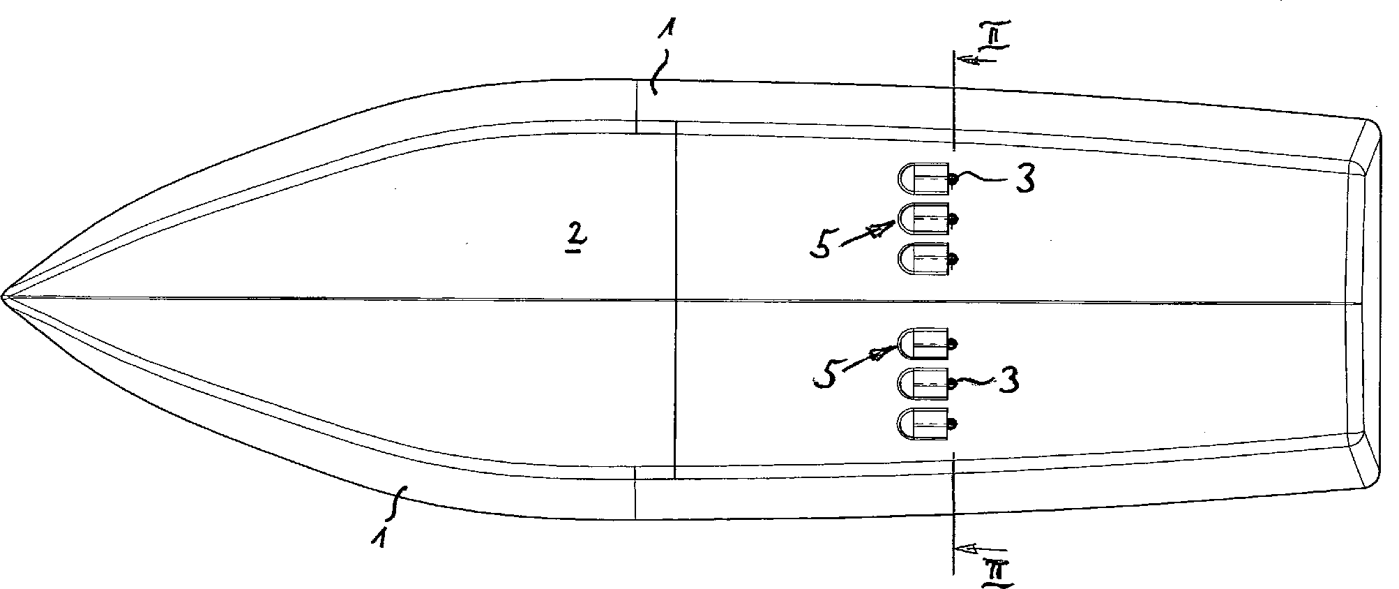
Andere Weiterbildungen und Ausgestaltungen der Erfindung sind in den übrigen Unteransprüchen angegeben. Ein Ausführungsbeispiel der Erfindung ist in der Zeichnung dargestellt und wird nachfolgend im Einzelnen beschrieben. Es zeigen:Other Further developments and embodiments of the invention are in the remaining Subclaims specified. An embodiment The invention is illustrated in the drawing and will be described below described in detail. Show it:
Der
als Ausführungsbeispiel dargestellte Bootsrumpf besteht
aus Bordwänden
Die
Hutzen
Im
Bereich der Saugöffnungen
An
die in den Luftzuführlöchern
An
dem den Luftzuführlöchern
Die
Vorrichtung zum Einbringen Luft unter einen Bootsrumpf besteht aus
einer Leitung
Der
Bootsrumpf ist in einfacher Weise mit der Vorrichtung zum Einbringen
von Luft unter den Bootsrumpf nachrüstbar. Hierzu ist es
lediglich erforderlich, die Luftzufuhrlöcher
Es
ist ersichtlich, dass diese Vorrichtung ohne weiteres nachträglich
montierbar ist. Dies ist dadurch bewerkstelligt, dass im Gegensatz
zum Stand der Technik keine Änderungen der natürlichen Rumpfkontur
erforderlich ist. Vielmehr ist der Bootsrumpf allein durch das Einbringen
der Luftzufuhrlöcher sowie die Anordnung der Saugöffnungen
Nach
der Montage erfolgt die Funktion der Vorrichtung in an sich bekannter
Weise. Beim Fahren des Bootes werden ab einer bestimmten Geschwindigkeit
die Absperrventile
ZITATE ENTHALTEN IN DER BESCHREIBUNGQUOTES INCLUDE IN THE DESCRIPTION
Diese Liste der vom Anmelder aufgeführten Dokumente wurde automatisiert erzeugt und ist ausschließlich zur besseren Information des Lesers aufgenommen. Die Liste ist nicht Bestandteil der deutschen Patent- bzw. Gebrauchsmusteranmeldung. Das DPMA übernimmt keinerlei Haftung für etwaige Fehler oder Auslassungen.This list The documents listed by the applicant have been automated generated and is solely for better information recorded by the reader. The list is not part of the German Patent or utility model application. The DPMA takes over no liability for any errors or omissions.
Zitierte PatentliteraturCited patent literature
- - EP 1685020 B1 [0003] - EP 1685020 B1 [0003]
Claims (13)
Priority Applications (1)
| Application Number | Priority Date | Filing Date | Title |
|---|---|---|---|
| DE202008013169U DE202008013169U1 (en) | 2008-10-07 | 2008-10-07 | Boat hull and device for introducing air under a boat hull |
Applications Claiming Priority (1)
| Application Number | Priority Date | Filing Date | Title |
|---|---|---|---|
| DE202008013169U DE202008013169U1 (en) | 2008-10-07 | 2008-10-07 | Boat hull and device for introducing air under a boat hull |
Publications (1)
| Publication Number | Publication Date |
|---|---|
| DE202008013169U1 true DE202008013169U1 (en) | 2008-12-24 |
Family
ID=40158022
Family Applications (1)
| Application Number | Title | Priority Date | Filing Date |
|---|---|---|---|
| DE202008013169U Expired - Lifetime DE202008013169U1 (en) | 2008-10-07 | 2008-10-07 | Boat hull and device for introducing air under a boat hull |
Country Status (1)
| Country | Link |
|---|---|
| DE (1) | DE202008013169U1 (en) |
Citations (1)
| Publication number | Priority date | Publication date | Assignee | Title |
|---|---|---|---|---|
| EP1685020B1 (en) | 2003-10-30 | 2007-10-10 | Chantiers Beneteau S.A. | Floating hull |
-
2008
- 2008-10-07 DE DE202008013169U patent/DE202008013169U1/en not_active Expired - Lifetime
Patent Citations (1)
| Publication number | Priority date | Publication date | Assignee | Title |
|---|---|---|---|---|
| EP1685020B1 (en) | 2003-10-30 | 2007-10-10 | Chantiers Beneteau S.A. | Floating hull |
Similar Documents
| Publication | Publication Date | Title |
|---|---|---|
| DE10163284B4 (en) | A method of manufacturing a variable vortex flow generation intake port | |
| DE102005042286A1 (en) | Device for separating a gas-liquid mixture | |
| EP2060484A1 (en) | Rudder for ships | |
| DE102007036999A1 (en) | Outflow valve for an aircraft | |
| DE112012000007T5 (en) | Construction machinery | |
| DE2851089A1 (en) | HYDRAULIC SUPPLY UNIT | |
| DE102019119321A1 (en) | ARRANGEMENT AND METHOD FOR FORMING A POLE FOR GUIDING A DRILL DRIVE IN AN HDD MACHINE | |
| EP0771941A1 (en) | Internal combustion engine cylinder head | |
| DE2636411C3 (en) | Ship for assembling and lowering implements into the water | |
| DE3701264A1 (en) | HYDRO BEARING | |
| DE102012202530A1 (en) | Cooling structure for a bearing housing of a turbocharger | |
| DE602004001438T2 (en) | Outlet channel, in particular for support strut of jet engines | |
| DE102005018560A1 (en) | pipe connection | |
| DE112008003325T5 (en) | Flush cover and two-stroke engine | |
| DE2909808A1 (en) | WATER-SAVING TOILET BOWL | |
| DE102009002712B4 (en) | Hot water heater and water distribution device for hot water heater | |
| DE202008013169U1 (en) | Boat hull and device for introducing air under a boat hull | |
| WO2012126677A1 (en) | Wet cell for a rail vehicle | |
| DE102012016068A1 (en) | Terminal device for hydrostatic machine, particularly axial piston machine, comprises terminal housing made of metal, in which multiple prepared openings are arranged to be suited depending on connection of hydrostatic machine | |
| DE4312799A1 (en) | Vacuum valve device for die casting | |
| EP3199715A2 (en) | Overflow for a basin, in particular rinsing basin | |
| DE202016103145U1 (en) | Top part of a street drain, with two-part spacers | |
| DE102013102027B4 (en) | Intake air duct for an internal combustion engine of a motor vehicle and motor vehicle | |
| DE102020114360A1 (en) | Torque-optimized air flap arrangement | |
| DE953203C (en) | Water cooling for a valve insert to be inserted into the cylinder head of an upright internal combustion engine from above |
Legal Events
| Date | Code | Title | Description |
|---|---|---|---|
| R207 | Utility model specification |
Effective date: 20090129 |
|
| R150 | Utility model maintained after payment of first maintenance fee after three years | ||
| R150 | Utility model maintained after payment of first maintenance fee after three years |
Effective date: 20111107 |
|
| R151 | Utility model maintained after payment of second maintenance fee after six years | ||
| R151 | Utility model maintained after payment of second maintenance fee after six years |
Effective date: 20141107 |
|
| R152 | Utility model maintained after payment of third maintenance fee after eight years | ||
| R071 | Expiry of right |