DE202008013473U1 - Device for pressing a profile strip on a vehicle window - Google Patents
Device for pressing a profile strip on a vehicle window Download PDFInfo
- Publication number
- DE202008013473U1 DE202008013473U1 DE202008013473U DE202008013473U DE202008013473U1 DE 202008013473 U1 DE202008013473 U1 DE 202008013473U1 DE 202008013473 U DE202008013473 U DE 202008013473U DE 202008013473 U DE202008013473 U DE 202008013473U DE 202008013473 U1 DE202008013473 U1 DE 202008013473U1
- Authority
- DE
- Germany
- Prior art keywords
- vehicle window
- pressing
- profile
- action
- line
- Prior art date
- Legal status (The legal status is an assumption and is not a legal conclusion. Google has not performed a legal analysis and makes no representation as to the accuracy of the status listed.)
- Expired - Lifetime
Links
Classifications
-
- B—PERFORMING OPERATIONS; TRANSPORTING
- B23—MACHINE TOOLS; METAL-WORKING NOT OTHERWISE PROVIDED FOR
- B23P—METAL-WORKING NOT OTHERWISE PROVIDED FOR; COMBINED OPERATIONS; UNIVERSAL MACHINE TOOLS
- B23P19/00—Machines for simply fitting together or separating metal parts or objects, or metal and non-metal parts, whether or not involving some deformation; Tools or devices therefor so far as not provided for in other classes
- B23P19/04—Machines for simply fitting together or separating metal parts or objects, or metal and non-metal parts, whether or not involving some deformation; Tools or devices therefor so far as not provided for in other classes for assembling or disassembling parts
- B23P19/047—Machines for simply fitting together or separating metal parts or objects, or metal and non-metal parts, whether or not involving some deformation; Tools or devices therefor so far as not provided for in other classes for assembling or disassembling parts for flexible profiles, e.g. sealing or decorating strips in grooves or on other profiles by devices moving along the flexible profile
-
- B—PERFORMING OPERATIONS; TRANSPORTING
- B60—VEHICLES IN GENERAL
- B60J—WINDOWS, WINDSCREENS, NON-FIXED ROOFS, DOORS, OR SIMILAR DEVICES FOR VEHICLES; REMOVABLE EXTERNAL PROTECTIVE COVERINGS SPECIALLY ADAPTED FOR VEHICLES
- B60J10/00—Sealing arrangements
- B60J10/20—Sealing arrangements characterised by the shape
- B60J10/26—Sealing arrangements characterised by the shape characterised by the surface shape
- B60J10/265—Sealing arrangements characterised by the shape characterised by the surface shape the surface being primarily decorative
-
- B—PERFORMING OPERATIONS; TRANSPORTING
- B60—VEHICLES IN GENERAL
- B60J—WINDOWS, WINDSCREENS, NON-FIXED ROOFS, DOORS, OR SIMILAR DEVICES FOR VEHICLES; REMOVABLE EXTERNAL PROTECTIVE COVERINGS SPECIALLY ADAPTED FOR VEHICLES
- B60J10/00—Sealing arrangements
- B60J10/45—Assembling sealing arrangements with vehicle parts
-
- B—PERFORMING OPERATIONS; TRANSPORTING
- B60—VEHICLES IN GENERAL
- B60J—WINDOWS, WINDSCREENS, NON-FIXED ROOFS, DOORS, OR SIMILAR DEVICES FOR VEHICLES; REMOVABLE EXTERNAL PROTECTIVE COVERINGS SPECIALLY ADAPTED FOR VEHICLES
- B60J10/00—Sealing arrangements
- B60J10/70—Sealing arrangements specially adapted for windows or windscreens
Landscapes
- Engineering & Computer Science (AREA)
- Mechanical Engineering (AREA)
- Automobile Manufacture Line, Endless Track Vehicle, Trailer (AREA)
Abstract
Vorrichtung
(10) zum Anpressen einer Profilleiste (60) an eine Fahrzeugscheibe
(70), mit einer Halterung (20) und einer darin ausgebildeten Anpresseinrichtung
(50), mit welcher die Profilleiste (60) und die Fahrzeugscheibe
(70) aneinander pressbar sind, dadurch gekennzeichnet,
• dass
die Anpresseinrichtung (50) ein erstes Andrückelement (51)
aufweist, welches die Profilleiste (60) und die Fahrzeugscheibe
(70) entlang einer Wirklinie (W) mit einer einstellbaren Kraft gegeneinander
presst, und
• dass die Anpresseinrichtung (50) ein
zweites Andrückelement (54) aufweist, mit welchem die Profilleiste
(60) quer zur Wirklinie (W) gegen die untere Stirnkante (72) der
Fahrzeugscheibe (70) pressbar ist.Device (10) for pressing a profiled strip (60) against a vehicle window (70), having a holder (20) and a pressing device (50) formed therein, with which the profiled strip (60) and the vehicle window (70) can be pressed against each other, characterized,
• that the pressing device (50) has a first pressing element (51) which presses the profiled strip (60) and the vehicle window (70) against each other along an operating line (W) with an adjustable force, and
• that the pressing device (50) has a second pressing element (54), with which the profile strip (60) can be pressed transversely to the line of action (W) against the lower end edge (72) of the vehicle window (70).
Description
Die Erfindung betrifft eine Vorrichtung zum Anpressen einer Profilleiste an eine Fahrzeugscheibe gemäß dem Oberbegriff von Anspruch 1.The The invention relates to a device for pressing a profile strip to a vehicle window according to the preamble of claim 1.
Bei Kraftfahrzeugen befindet sich unterhalb der Windschutzscheibe gewöhnlich ein Wasserkasten, der von der Scheibe abfließendes Wasser auffängt und seitlich abführt. Zur Festlegung und Abdichtung des Wasserkastens an der Unterkante der Fahrzeugscheibe verwendet man meist einen extrudierten Profilkörper oder Profilstrang, der mit dem unteren Rand der Fahrzeugscheibe verklebt wird.at Motor vehicles are usually located below the windshield a water tank, the water flowing from the glass catches and dissipates sideways. To lay down and sealing the water box at the lower edge of the vehicle window one usually uses an extruded profile body or Profile strand glued to the lower edge of the vehicle window becomes.
Der
Profilkörper hat – wie beispielsweise in
Aus
Eine solche Vorrichtung ist relativ groß und für die rationelle Serienfertigung großer Stückzahlen ausgelegt. Ferner sind die Anschaffungskosten aufgrund des apparativen Aufbaus sehr hoch, so dass sich der Einsatz in kleineren Werkstätten, die Windschutzscheiben als Ersatzteile anbieten und einbauen, nicht lohnt.A Such device is relatively large and for the rational mass production of large quantities designed. Furthermore, the acquisition costs due to the apparatus design very high, so the use in smaller workshops, not offering and installing the windshields as spare parts worth.
Es
sind bereits auch kleinere Handwerkzeuge bekannt, um Profilleisten
zu montieren. So beschreibt beispielsweise
Nachteilig hierbei ist, dass das Werkzeug nur ein bestimmtes U-Profil aufnehmen kann und nicht universell für verschiedene Profilleisten einsetzbar ist. Ferner muss das Profil mittels der Rollen leicht aufgebogen werden, um es auf die Flanschkante aufschieben zu können. Das Anbringen eines Wasserkastenprofils ist mit einem solchen Werkzeug nicht möglich.adversely Here it is that the tool only pick up a specific U-profile can and not universally for different moldings can be used. Furthermore, the profile must be slightly bent by means of the rollers be able to postpone it to the flange edge. The attachment of a water box profile is with such a tool not possible.
Das
gleiche gilt für eine in
Ziel der Erfindung ist es diese und weitere Nachteile des Standes der Technik zu überwinden und eine Vorrichtung zu schaffen, mit der unterschiedliche Profilleisten rasch und bequem am unteren Rand einer Fahrzeugscheibe angebracht werden können. Die Vorrichtung soll mit einfachen Mitteln kostengünstig aufgebaut sein und ohne Fremdenergie auskommen. Angestrebt wird ferner ein handliches und kompaktes Design, das ein stets zuverlässiges und reproduzierbares Anpressen der Profilleiste gewährleistet.aim the invention, it is these and other disadvantages of the prior Overcome technology and create a device with the different moldings quickly and conveniently at the bottom Edge of a vehicle window can be attached. The Device should be constructed inexpensively with simple means be and get along without external energy. The aim is also a Handy and compact design that is always reliable and ensures reproducible pressing of the profile strip.
Hauptmerkmale der Erfindung sind im kennzeichnenden Teil von Anspruch 1 angegeben. Ausgestaltungen sind Gegenstand der Ansprüche 2 bis 21.main features The invention are specified in the characterizing part of claim 1. Embodiments are the subject of claims 2 to 21.
Bei einer Vorrichtung zum Anpressen einer Profilleiste an eine Fahrzeugscheibe, mit einer Halterung und einer darin ausgebildeten Anpresseinrichtung, mit welcher die Profilleiste und die Fahrzeugscheibe aneinander pressbar sind, sieht die Erfindung vor, dass die Anpresseinrichtung ein erstes Andrückelement aufweist, welches die Profilleiste und die Fahrzeugscheibe entlang einer Wirklinie mit einer einstellbaren Kraft gegeneinander presst, und dass die Anpresseinrichtung ein zweites Andrückelement aufweist, mit welchem die Profilleiste quer zur Wirklinie gegen die untere Stirnkante der Fahrzeugscheibe pressbar ist.at a device for pressing a profile strip on a vehicle window, with a holder and a pressing device formed therein, with which the profile strip and the vehicle window to each other are pressed, the invention provides that the pressing device a first pressing element having the profile strip and the vehicle window along a line of action with an adjustable Force presses against each other, and that the pressing device a having second pressing element, with which the profile strip Pressable transversely to the line of action against the lower end edge of the vehicle window is.
Mit dieser ebenso einfach wie kostengünstig zu realisierenden Vorrichtung lässt sich die Profilleiste von Hand mit der Unterkante der Fahrzeugscheibe verpressen, indem die Vorrichtung einmal über die gesamte Breite der Fahrzeugscheibe bzw. die Länge der Profilleiste bewegt wird. Dabei wird die Profilleiste in zwei Richtungen gegen die Fahrzeugscheibe gepresst. Zum einen werden die Profilleiste und die Fahrzeugscheibe entlang einer Wirklinie von der ersten Anpresseinrichtung gegeneinander gepresst, so dass die Profilleiste fest mit der Fahrzeugscheibe verbunden wird. Zum anderen wird das Profil mit der zweiten Anpresseinrichtung gleichzeitig von Hand gegen die untere Stirnkante der Fahrzeugscheibe gepresst, so dass das Profil stets formschlüssig und dicht an der Scheibe anliegt.With this simple as well as inexpensive to implement device can the profile track te by hand with the lower edge of the vehicle window by the device once over the entire width of the vehicle window or the length of the profile strip is moved. The profile strip is pressed in two directions against the vehicle window. On the one hand, the profile strip and the vehicle window are pressed against each other along a line of action by the first pressing device, so that the profile strip is firmly connected to the vehicle window. On the other hand, the profile with the second pressing device is simultaneously pressed by hand against the lower end edge of the vehicle window, so that the profile always rests positively and tightly against the disc.
Obwohl die Vorrichtung als Handgerät ausgebildet ist, das einfach und rationell bedienbar ist, wird die für das Profilelement und dessen Klebestreifen notwendige Anpresskraft nicht von dem Bediener aufgebracht, sondern von der Vorrichtung selbst. Lediglich die Anpresskraft in Richtung Fahrzeug-Stirnkante wird von dem Bediener erzeugt. Diese Kraftkomponente muss jedoch lediglich dafür sorgen, dass die Profilleiste stets formschlüssig und dicht an der Stirnkante der Scheibe anliegt. Die Profilleiste und die Fahrzeugscheibe hingegen werden von einer vom Bediener unabhängigen, vorgebbaren bzw. einstellbaren Kraft gegeneinander gepresst. Diese Kraft kann mithin so eingestellt werden, dass das zwischen dem Profilelement und der Fahrzeugscheibe vorgesehene doppelseitige Klebeband stets optimal verpresst wird.Even though the device is designed as a handheld device, easy and is rationally operable, which is for the profile element and whose adhesive strip does not apply necessary contact force by the operator, but of the device itself. Only the contact pressure in Direction vehicle front edge is generated by the operator. These Force component must, however, only ensure that the profile strip always form-fitting and close to the front edge the disc rests. The profile strip and the vehicle window, however are from an operator-independent, specifiable or adjustable force pressed against each other. This power can Thus be set so that between the profile element and the vehicle window provided double-sided tape always is pressed optimally.
Dem ersten Andrückelement ist ein Gegenlager zugeordnet, welches die Profilleiste und/oder die Fahrzeugscheibe abstützt. Das Gegenlager nimmt mithin die von dem Andrückelement erzeugte Kraft auf, die unmittelbar und vollständig auf die Profilleiste bzw. deren Klebestreifen einwirken kann.the first pressing element is associated with an abutment, which the profile strip and / or the vehicle window is supported. The anvil thus takes those of the pressure element generated force, the immediate and complete the profile strip or its adhesive strip can act.
Der Klebestreifen wird damit nicht bloß von Hand und mit einer undefinierten oder ungleichmäßigen Kraft verpresst. Die erfindungsgemäße Vorrichtung gewährleistet vielmehr, dass die Profilleiste und die Fahrzeugscheibe mit dem dazwischen angeordneten Klebestreifen über die gesamte Breite der Fahrzeugscheibe stets mit ein und derselben vordefinierten Kraft gegeneinander verpresst werden. Der Klebestreifen kann dadurch stets seine optimale Haltekraft entfalten.Of the Adhesive tape is thus not just by hand and with a undefined or uneven force pressed. The device of the invention ensures Rather, that the profile strip and the vehicle window with the between them arranged adhesive strips over the entire Width of the vehicle window always with one and the same predefined Force pressed against each other. The adhesive strip can thereby always develop its optimal holding power.
Eine wichtige Weiterbildung der Erfindung sieht vor, dass das erste Andrückelement und das Gegenlager fluchtend auf der Wirklinie ausgebildet sind, wobei die Wirklinie senkrecht zur Fahrzeugscheibe ausgerichtet ist. Ferner wird die Profilleiste von dem ersten Andrückelement und dem Gegenlager gegen eine Seitenfläche der Fahrzeugscheibe gedrückt. Dadurch kann die von dem ersten Andrückelement aufgebrachte Anpresskraft vollständig und gleichmäßig auf das Profilelement und die Fahrzeugscheibe einwirken. Die gesamte Vorrichtung gewährleistet mithin ein zuverlässiges und reproduzierbares Verpressen der Profilleiste mit der Fahrzeugscheibe, wobei die Leiste stets positionsgerecht fixiert wird. Sie kann – nach dem Aushärten des Klebers – passgenau die einspringende Rippe des Wasserkastens aufnehmen.A important development of the invention provides that the first pressure element and the counter bearing are aligned on the action line, wherein the line of action is aligned perpendicular to the vehicle window. Furthermore, the profile strip of the first pressure element and the abutment pressed against a side surface of the vehicle window. As a result, the applied by the first pressure element Contact pressure complete and even acting on the profile element and the vehicle window. The whole Device thus ensures a reliable and reproducible pressing the profile strip with the vehicle window, wherein the bar is always fixed in position. She can - after the curing of the adhesive - exactly the re-entrant Pick up the rib of the water box.
Um die für das Verpressen des Klebestreifens erforderliche Kraft reproduzierbar aufbringen zu können, ist das erste Andrückelement entlang der Wirklinie verschiebbar gelagert und von einer Anpresskraft belastet, wobei die Anpresskraft parallel zur Wirklinie in Richtung der Fahrzeugscheibe wirkt. Gleichzeitig kann die Vorrichtung auch bei Profilleisten und Fahrzeugscheiben unterschiedlicher Dicke angewendet wenden.Around the required for the pressing of the adhesive strip Being able to apply force reproducibly is the first Pressure element displaceably mounted along the line of action and loaded by a contact force, wherein the contact force parallel to the line of action acts in the direction of the vehicle window. At the same time, the device can also applied to moldings and vehicle windows of different thickness turn.
Eine weitere Ausführungsform sieht vor, dass die Anpresskraft von einer Feder erzeugt wird, die bevorzugt vorspannbar ist. Auf diese Weise ist die Anpresskraft nicht nur unabhängig von der Handhabung der Vorrichtung. Diese kann vielmehr rasch und bequem an unterschiedliche Anforderungen verschiedener Klebestreifen angepasst werden. Letztere werden stets mit der erforderlichen Presskraft beaufschlagt, um eine feste und dauerhafte Verbindung zu schaffen.A Another embodiment provides that the contact pressure is generated by a spring, which is preferably biased. On In this way, the contact pressure is not only independent of the handling of the device. It can be done quickly and easily adapted to different requirements of different adhesive strips become. The latter are always with the required pressing force to create a strong and lasting connection.
Um die eingestellte Vorspannkraft der Feder und damit die Anpresskraft erkennen zu können, kann an der Vorrichtung bzw. an der Halterung eine Skala und/oder eine Markierung vorgesehen sein, die bequem ablesbar ist.Around the set preload force of the spring and thus the contact pressure can recognize on the device or on the Holder be provided a scale and / or a mark, the is easy to read.
Das erste Andrückelement ist bevorzugt eine Rolle, die drehbar gelagert ist. Das Gegenlager ist ebenfalls eine drehbar gelagerte Rolle, wodurch die Vorrichtung nahezu reibungslos über die Scheibe bzw. die Profilleiste geführt werden kann. Der Kraftaufwand für das Bewegen der Vorrichtung ist – trotz definierter Anpresskraft von z. B. 200 N – äußerst gering. Alternativ kann man als Andrückelement auch eine Kufe, einen Schlitten o. dgl. verwenden kann. Das gleiche gilt für das Gegenlager, das ebenfall eine Kufe, ein Schlitten o. dgl. sein kann.The first pressing element is preferably a roller which is rotatable is stored. The anvil is also a rotatably mounted Role, causing the device almost smoothly over the disc or the profile strip can be performed. The force required to move the device is - despite defined Contact pressure of z. B. 200 N - extremely low. Alternatively, you can as a pressing element and a Skid, a slide o. The like. Can use. The same applies the anvil, which is also a skid, a sled, or the like can.
Um die erfindungsgemäße Vorrichtung an der Profilleiste und der Schreibe ansetzen zu können, ist das erste Andrückelement mittels einer Schwenkvorrichtung relativ zur Wirklinie ein- und ausschwenkbar. Das erste Andrückelement lässt sich mithin beim Ansetzen der Vorrichtung bequem zur Seite schwenken und – sobald die Vorrichtung sich in Position befindet – wieder einschwenken. In dieser Position ist die Schwenkvorrichtung arretierbar, so dass das Andrückelement während dem Anpressvorgang seine Position auf der Wirklinie einhält.Around the device according to the invention on the profile strip and to be able to start writing is the first pressing element by means of a pivoting device relative to the line of action on and swung. The first pressing element leaves Therefore, when setting the device convenient to swing aside and - once the device is in position - again Engage. In this position, the pivoting device can be locked, so that the pressure element during the pressing process maintains its position on the line of action.
Zum Ein- und Ausschwenken des ersten Andrückelements weist die Schwenkvorrichtung ein Betätigungselement auf. Über dieses ist zweckmäßig zugleich auch die Vorspannung der Feder einstellbar, wodurch sich die Zahl der Bauelemente deutlich reduziert. Die Vorrichtung ist einfach aufgebaut und kostengünstig zu realisieren.To the Swiveling in and out of the first pressing element has the pivoting device on an actuating element. about this is useful at the same time also the bias adjustable spring, which significantly increases the number of components reduced. The device is simple and inexpensive to realize.
Um die Vorrichtung an unterschiedliche Profilleisten bzw. deren Geometrien anpassen zu können, sieht die Erfindung weiter vor, dass der Abstand des zweiten Andrückelements relativ zur Wirklinie des ersten Andrückelement und des Gegenlagers einstellbar ist. Sobald daher das zweite Andrückelement an der Profilleiste anliegt, ist sicher gestellt, dass sich die Wirklinie zwischen dem ersten Andrückelement und dem Gegenlager stets über dem Profilelement bzw. mittig über dessen Klebestreifen liegt. Profilelement und Fahrzeugscheibe werden damit stets optimal miteinander verpresst.Around the device to different moldings or their geometries to be able to adapt, the invention further provides that the distance of the second pressing element relative to the line of action of the first pressing element and the thrust bearing is adjustable. Therefore, as soon as the second pressing element on the profile strip is ensured that the line of action between the first pressure element and the anvil always over the profile element or centrally over the adhesive strip lies. Profile element and vehicle window are thus always optimal pressed together.
Zweckmäßig ist das zweite Andrückelement in oder an der Halterung senkrecht zur Wirklinie verschiebbar gelagert, wobei das zweite Andrückelement mittels eines Stellglieds verschiebbar ist. Letzteres ist manuell betätigbar, so dass die Vorrichtung ohne jede Energieversorgung oder Fremdenergie auskommt.expedient is the second pressing element in or on the holder slidably mounted perpendicular to the line of action, wherein the second Pressure element is displaceable by means of an actuator. The latter is manually operable, so that the device without every energy supply or external energy gets by.
Die erfindungsgemäße Vorrichtung ist vielmehr ein kompaktes kleines Handgerät, mit dem verschiedene Profilleisten stets zuverlässig und ohne große Kraftanstrengung an Fahrzeugscheiben angebracht werden können. Die einfache Handhabung des Handgeräts ermöglicht zudem eine rasche und präzise Arbeitsweise, selbst durch ungeschultes oder ungeübtes Personal.The inventive device is rather a compact small handset, with the different profile strips always reliable and without great effort can be attached to vehicle windows. The simple one Handling the handset also allows a fast and precise operation, even by untrained or untrained staff.
Das zweite Andrückelement ist bevorzugt eine Rolle, die drehbar gelagert ist. Man kann aber auch eine (Gleit)Kufe, einen Schlitten o. dgl. vorsehen.The second pressing element is preferably a roller which is rotatable is stored. But you can also a (sliding) skid, a sled o. Provide.
Eine weitere wichtige Ausgestaltung der Erfindung sieht vor, dass das zweite Andrückelement profiliert ausgebildet ist. Diese Profilierung ist derart ausgebildet, dass die Profilleiste nicht nur senkrecht zur Wirklinie des ersten Andrückelements und des Gegenlagers gegen die untere Stirnkante der Fahrzeugscheibe gepresst wird, sondern dass die Profilleiste zugleich auch gegen die Seitenfläche der Fahrzeugscheibe gedrückt wird. Dadurch ist gewährleistet, dass die Profilleiste stets formschlüssig an der Fahrzeugscheibe anliegt, insbesondere, dass das Dichtelement der Profilleiste stets formschlüssig an der Stirnkante der Fahrzeugscheibe anliegt und etwa Flächenbündig mit deren Oberseite abschließt.A Another important embodiment of the invention provides that the second pressing element is formed profiled. These Profiling is designed such that the profile bar is not only perpendicular to the line of action of the first pressure element and the abutment against the lower end edge of the vehicle window is pressed, but that the profile strip at the same time against pressed the side surface of the vehicle window becomes. This ensures that the profile strip always positively applied to the vehicle window, in particular, that the sealing element of the profile strip always positive fit rests against the front edge of the vehicle window and approximately flush with their top ends.
Die Führung der Vorrichtung entlang der Profilleiste bzw. entlang der Scheibenkante lässt sich weiter verbessern, indem zwei zweite Andrückelemente vorgesehen sind, die parallel zur Stirnkante der Fahrzeugscheibe angeordnet sind. Die Vorrichtung kann damit während der Handhabung nicht seitlich verkippen. Zudem wird die Profilleiste an zwei Stellen gegen die Stirnkante der Fahrzeugscheibe gepresst.The Guide the device along the profile strip or along the pane edge can be further improved by two second pressing elements are provided, which are parallel to Front edge of the vehicle window are arranged. The device can not tilt sideways during handling. In addition, the profile strip is in two places against the front edge pressed the vehicle window.
Um Profilleisten verarbeiten zu können, die an ihrer Unterseite mit einer Pufferleiste aus einer weicheren Komponente versehen sind, sieht die Erfindung vor, dass die Halterung eine Aussparung für das Profilelement aufweist.Around To be able to process profile strips on their underside with a buffer strip made of a softer component, the invention provides that the holder has a recess for the Profile element has.
Weitere Merkmale, Einzelheiten und Vorteile der Erfindung ergeben sich aus dem Wortlaut der Ansprüche sowie aus der folgenden Beschreibung von Ausführungsbeispielen anhand der Zeichnungen. Es zeigen:Further Features, details and advantages of the invention will become apparent the wording of the claims and the description below of embodiments with reference to the drawings. Show it:
Die
in
Die
Profilleiste
In
der Rastausnehmung
Unterhalb
der Rastausnehmung
Die
Festlegung der Profilleiste
Die
Halterung
Die
an bzw. in der Halterung
Die
Andrückrolle
Die
Andrückrolle
Über
dem Gleitstück
Man
erkennt, dass das Gleitstück
Dadurch
ist das erste Andrückelement
Die
Kraft der Feder
Um
die Profilleiste
Die
Betätigung der Schwenkvorrichtung
Verschwenkt
man die kreisrunde Halterung
Die
Vorrichtung
Man
erkennt, dass das erste Andrückelement
Damit
die Andrückrolle
Wie
Dazu
sind innerhalb der Halterung
Rückseitig
ist der Rahmen
Dreht
man die Rändelscheibe
Damit
die Profilleiste
Die
vordere Stirnseite des unteren Schenkels
Das
Anbringen einer Profilleiste
- 1. Die Fahrzeugscheibe
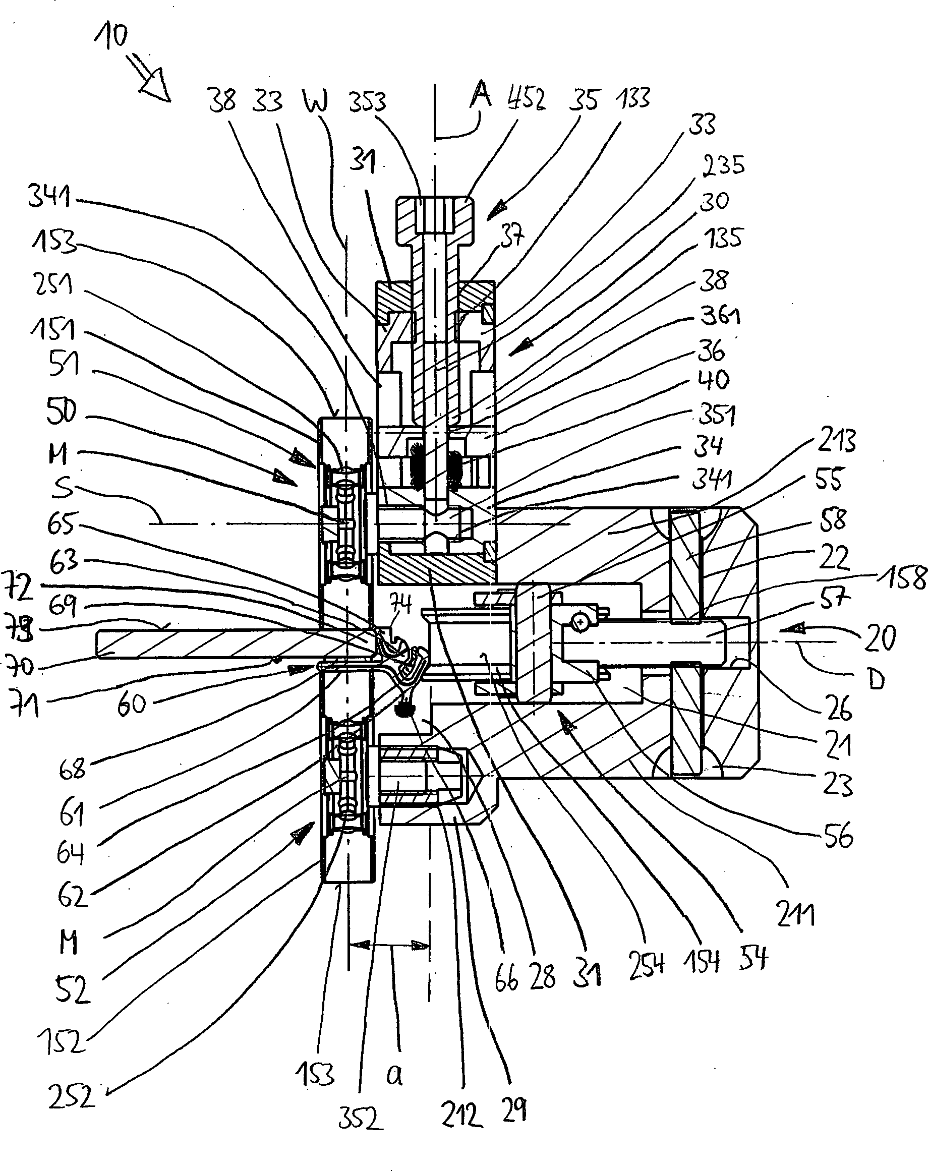
70 wird zunächst auf einem (nicht gezeigten) Tisch oder einem Bock abgelegt oder in stabiler Position aufgestellt. Die Vorrichtung10 wird über das Betätigungselement35 geöffnet, indem die Andrückrolle151 des ersten Andrückelements51 mittels der in dem Gehäuse31 schwenkbar gelagerten Halterung33 zur Seite und nach oben geschwenkt wird. Anschließend wird die Profilleiste60 mit einer markierten Stelle mittig an die ebenfalls gekennzeichnete Mitte der Autoscheibe70 gehalten und die Vorrichtung10 von unten an die Scheibe70 bzw. an das Profilelement61 angesetzt. Dabei wird die Andrückrolle152 des Gegenlagers52 von unten auf das Profilelement61 aufgesetzt, während die Andrückrollen154 des zweiten Andrückelements54 an den Federschenkel62 des Profilelements61 angelegt werden. Mittels der Rändelscheibe58 wird – sofern notwendig – der Abstand a zwischen der horizontalen Andrückrolle154 und der Wirklinie W derart eingestellt, dass die Andrückrolle152 des Gegenlagers52 möglichst exakt zur Längsmitte des Klebestreifens68 auf dem Profilelement61 positioniert ist. Sodann wird die Vorrichtung10 geschlossen, indem das Betätigungselement35 innerhalb der Umfangsausnehmung37 in seine Ausgangsposition parallel zur Wirklinie W zurückgeschwenkt wird. Dabei wird das erste Andrückelement51 wieder auf die Wirklinie W eingeschwenkt und von den Feder40 auf die Oberseite73 der Scheibe70 gedrückt. Durch Drehen des Betätigungselements35 um die Achse A kann noch die Vorspannung der Feder40 und damit die Kraft, mit der das Profilelement61 bzw. dessen Klebestreifen68 gegen die Scheibe70 gepresst wird, eingestellt werden. Dies erfolgt bevorzugt mit Hilfe der Anzeigeeinrichtung41 , die anzeigt, mit welcher Kraft die Feder40 die Profilleiste60 und die Scheibe70 aufeinander presst. Durch die Längsverstellung des Gleitelements34 entlang der Wirklinie W innerhalb der Halterung33 kann die Vorrichtung10 gleichzeitig auch an unterschiedliche Stärken bzw. Dicken der Fahrzeugscheibe70 angepasst werden, indem die Position der ersten Andrückrolle151 gegenüber der Gegenlager-Rolle152 eingestellt wird. - 2. Sobald alle Einstellungen vorgenommen worden sind und die
Vorrichtung
10 geschlossen ist, wird die Halterung33 in dem Gehäuse31 über den Raststift39 verriegelt. Sodann kann die Profilleiste60 durch einfaches Bewegen der Vorrichtung10 entlang der Scheibenkante74 an der Fahrzeugscheibe70 festgelegt werden. Das Anpressen der Profilleiste entlang der Wirklinie W erfolgt dabei mit konstanter Kraft, während das Andrücken der Vorrichtung10 an den Federschenkel62 des Profilelements61 dafür sorgt, dass das Profilelemente61 optimal positioniert ist und die Dichtlippe65 der Profilleiste60 stets dicht an der Stirnfläche72 der Scheibe70 anliegt. Dazu trägt auch die Profilierung der Andrückrolle154 bei, welche das Profilelemente61 nicht nur in Richtung Stirnkante72 drückt, sondern auch schräg nach oben in Richtung Scheiben-Oberkante74 . Wurde die Vorrichtung10 einmal über die gesamte Länge der Scheibenkante74 bzw. die gesamte Länge der Profilleiste60 bewegt, ist letztere an der Scheibe70 fixiert. Die Vorrichtung10 kann geöffnet und abgenommen werden. Sollen weitere Profile60 gleicher Geometrie angebracht werden, kann die Vorrichtung10 ohne Einstellungsveränderungen sofort weiter benutzt werden.
- 1. The vehicle window
70 is first placed on a (not shown) table or a stand or placed in a stable position. The device10 is via the actuator35 opened by the pressure roller151 of the first pressing element51 by means of in the housing31 pivotally mounted bracket33 is swung to the side and up. Subsequently, the profile bar60 with a marked point in the middle of the also marked center of the car window70 kept and the device10 from below to the disc70 or to the profile element61 stated. This is the pressure roller152 of the counter bearing52 from below on the profile element61 put on while the pressure rollers154 of the second pressing element54 to the spring leg62 of the profile element61 be created. By means of the thumb wheel58 If necessary, the distance a between the horizontal pressure roller154 and the line of action W set such that the pressure roller152 of the counter bearing52 as exactly as possible to the longitudinal center of the adhesive strip68 on the profile element61 is positioned. Then the device10 closed by the actuator35 within the circumferential recess37 is pivoted back into its initial position parallel to the line of action W. In this case, the first pressure element51 pivoted back to the action line W and from the spring40 on top73 the disc70 pressed. By turning the actuator35 about the axis A can still the bias of the spring40 and therefore the force with which the profile element61 or its adhesive strip68 against the disc70 is pressed, be set. This is preferably done with the aid of the display device41 indicating with what force the spring40 the profile bar60 and the disc70 pressed together. By the longitudinal adjustment of the sliding element34 along the line of action W within the holder33 can the device10 at the same time also to different thicknesses or thicknesses of the vehicle window70 be adjusted by the position of the first pressure roller151 opposite the counter-bearing roller152 is set. - 2. Once all settings have been made and the device
10 is closed, the holder is33 in the case31 over the detent pin39 locked. Then the profile strip60 by simply moving the device10 along the window edge74 on the vehicle window70 be determined. The pressing of the profiled strip along the line of action W takes place with a constant force, while the pressing of the device10 to the spring leg62 of the profile element61 Ensures that the profile elements61 is optimally positioned and the sealing lip65 the profile strip60 always close to the face72 the disc70 is applied. This is also helped by the profiling of the pressure roller154 at which the profile elements61 not just towards the front edge72 pushes, but also obliquely upwards in the direction of the disc top edge74 , Became the device10 once over the entire length of the window edge74 or the entire length of the profile strip60 moved, the latter is at the disc70 fixed. The device10 can be opened and removed. Should more profiles60 the same geometry can be attached, the device10 be used immediately without changes in settings.
Wesentliche
Vorteile der Erfindung bestehen darin, die Vorrichtung
Die
Andrückrolle
Aufgrund
der exzentrischen Anordnung der Rolle
Über
die horizontal liegenden Andrückrollen
Die
Erfindung ist nicht auf eine der vorgeschriebenen Ausführungsformen
beschränkt, sondern in vielfältiger Weise abwandelbar.
So können das Gegenlager
Durch
unterschiedlich eingebaute Federn können verschiedene Kräfte
auf die Scheibe
Zu
erwähnen ist ferner, dass die Vorrichtung
Man
erkennt, dass es sich bei der Vorrichtung
Sämtliche aus den Ansprüchen, der Beschreibung und der Zeichnung hervorgehenden Merkmale und Vorteile, einschließlich konstruktiver Einzelheiten, räumlicher Anordnungen und Verfahrensschritten, können sowohl für sich als auch in den verschiedensten Kombinationen erfindungswesentlich sein.All from the claims, the description and the drawing resulting features and benefits, including constructional details, spatial arrangements and method steps, can both for yourself and in various combinations be essential to the invention.
- AA
- Achseaxis
- DD
- Achseaxis
- LL
- Längsrichtunglongitudinal direction
- MM
- MittelpunktFocus
- SS
- Achseaxis
- WW
- Wirklinieline of action
- 1010
- Vorrichtungcontraption
- 2020
- Halterungbracket
- 2121
- Ausnehmungrecess
- 211211
- unterer Schenkellower leg
- 212212
- Gewindebohrungthreaded hole
- 213213
- oberer Schenkelupper leg
- 214214
- Schraubescrew
- 2222
- Aussparungrecess
- 2323
- Vertiefungdeepening
- 2626
- Bohrungdrilling
- 2828
- Stufestep
- 2929
- Absatzparagraph
- 3030
- Schwenkvorrichtungswivel device
- 3131
- Gehäusecasing
- 3333
- kreisrunde Halterungencircular brackets
- 133133
- Gewindebohrungthreaded hole
- 3434
- Gleitstückslide
- 341341
- Gewindebohrungthreaded hole
- 3535
- Betätigungselementactuator
- 135135
- untere Endenlower end up
- 235235
- Bolzenbolt
- 452452
- Kopfhead
- 353353
- Ausnehmungrecess
- 3636
- DruckstückPressure piece
- 361361
- Bohrungdrilling
- 3737
- Umfangsausnehmungcircumferential
- 3838
- Längsausnehmunglongitudinal recess
- 3939
- RaststiftPlunger
- 4040
- Federfeather
- 4141
- Anzeigeeinrichtungdisplay
- 5050
- Anpresseinrichtungpressing device
- 5151
- erste Andrückelementfirst pressing element
- 151151
- Andrückrollecapstan
- 251251
- Kugellagerball-bearing
- 351351
- Achsbolzenaxle
- 5252
- Gegenlagerthrust bearing
- 152152
- Andrückrollecapstan
- 153153
- Außenflächenexterior surfaces
- 252252
- Kugellagerball-bearing
- 352352
- Achsbolzenaxle
- 5454
- zweite Andrückelementsecond pressing element
- 154154
- Andrückrollecapstan
- 254254
- Außenflächeouter surface
- 5555
- Rahmenframe
- 5656
- Adapteradapter
- 5757
- Schraubbolzenbolts
- 5858
- Rändelscheibethumbwheel
- 158158
- Gewindebohrungthreaded hole
- 6060
- ProfilleisteMolding
- 6161
- Profilelementprofile element
- 6262
- Federschenkelspring leg
- 6363
- KeilrippeV-rib
- 6464
- Rastausnehmungrecess
- 6565
- Dichtlippesealing lip
- 6666
- PufferleisteSlack bar
- 6868
- Klebestreifensadhesive strip
- 6969
- KunststoffleistePlastic strip
- 7070
- Fahrzeugscheibevehicle window
- 7171
- Seitenflächeside surface
- 7272
- Stirnkantefront edge
- 7373
- Oberseitetop
- 7474
- Oberkantetop edge
ZITATE ENTHALTEN IN DER BESCHREIBUNGQUOTES INCLUDE IN THE DESCRIPTION
Diese Liste der vom Anmelder aufgeführten Dokumente wurde automatisiert erzeugt und ist ausschließlich zur besseren Information des Lesers aufgenommen. Die Liste ist nicht Bestandteil der deutschen Patent- bzw. Gebrauchsmusteranmeldung. Das DPMA übernimmt keinerlei Haftung für etwaige Fehler oder Auslassungen.This list The documents listed by the applicant have been automated generated and is solely for better information recorded by the reader. The list is not part of the German Patent or utility model application. The DPMA takes over no liability for any errors or omissions.
Zitierte PatentliteraturCited patent literature
- - DE 20008555 U1 [0003] - DE 20008555 U1 [0003]
- - DE 102006031821 A1 [0004] DE 102006031821 A1 [0004]
- - DE 4035366 A1 [0006] - DE 4035366 A1 [0006]
- - DE 4327067 A1 [0008] - DE 4327067 A1 [0008]
Claims (21)
Priority Applications (1)
| Application Number | Priority Date | Filing Date | Title |
|---|---|---|---|
| DE202008013473U DE202008013473U1 (en) | 2008-10-14 | 2008-10-14 | Device for pressing a profile strip on a vehicle window |
Applications Claiming Priority (1)
| Application Number | Priority Date | Filing Date | Title |
|---|---|---|---|
| DE202008013473U DE202008013473U1 (en) | 2008-10-14 | 2008-10-14 | Device for pressing a profile strip on a vehicle window |
Publications (1)
| Publication Number | Publication Date |
|---|---|
| DE202008013473U1 true DE202008013473U1 (en) | 2009-04-09 |
Family
ID=40530926
Family Applications (1)
| Application Number | Title | Priority Date | Filing Date |
|---|---|---|---|
| DE202008013473U Expired - Lifetime DE202008013473U1 (en) | 2008-10-14 | 2008-10-14 | Device for pressing a profile strip on a vehicle window |
Country Status (1)
| Country | Link |
|---|---|
| DE (1) | DE202008013473U1 (en) |
Cited By (6)
| Publication number | Priority date | Publication date | Assignee | Title |
|---|---|---|---|---|
| WO2011045494A1 (en) * | 2009-10-16 | 2011-04-21 | Peugeot Citroën Automobiles SA | Tool for placing a joint in a leaf rebate of a vehicle |
| FR2996156A1 (en) * | 2012-10-02 | 2014-04-04 | Peugeot Citroen Automobiles Sa | Applicator for applying opening frame joint on rabbet of e.g. door opening on body of car, has stems for releasing application casters when force applied on application casters is higher than predetermined value and is exerted on frame |
| US9260632B2 (en) | 2011-10-14 | 2016-02-16 | 3M Innovative Properties Company | Primerless multilayer adhesive film for bonding glass substrates |
| DE102015217464A1 (en) * | 2015-09-11 | 2017-03-16 | Volkswagen Aktiengesellschaft | Method for mechanically locking a joining part with a base part and joining tool therefor |
| DE102016213297A1 (en) * | 2016-07-20 | 2018-01-25 | Thyssenkrupp Ag | Application unit with measuring device for attaching a sealing profile and method |
| EP2658736B1 (en) | 2010-12-30 | 2019-08-21 | Rehau AG + Co | Sealing profile for connecting a water tank cover to a window pane and corresponding assembly method |
Citations (4)
| Publication number | Priority date | Publication date | Assignee | Title |
|---|---|---|---|---|
| DE4035366A1 (en) | 1989-11-22 | 1991-05-23 | Draftex Ind Ltd | DEVICE FOR FASTENING A U-SHAPED PROFILE BAR ON A FLANGE OR THE LIKE |
| DE4327067A1 (en) | 1993-08-12 | 1995-02-16 | Bayerische Motoren Werke Ag | Mounting device for a sealing profile to be pushed onto a flange |
| DE20008555U1 (en) | 2000-05-12 | 2000-08-17 | Elkamet Kunststofftechnik GmbH, 35216 Biedenkopf | Sealing arrangement for vehicle windows |
| DE102006031821A1 (en) | 2006-07-07 | 2008-01-10 | Elkamet Kunststofftechnik Gmbh | Mounting device and assembly method for mounting a profile on a pane |
-
2008
- 2008-10-14 DE DE202008013473U patent/DE202008013473U1/en not_active Expired - Lifetime
Patent Citations (4)
| Publication number | Priority date | Publication date | Assignee | Title |
|---|---|---|---|---|
| DE4035366A1 (en) | 1989-11-22 | 1991-05-23 | Draftex Ind Ltd | DEVICE FOR FASTENING A U-SHAPED PROFILE BAR ON A FLANGE OR THE LIKE |
| DE4327067A1 (en) | 1993-08-12 | 1995-02-16 | Bayerische Motoren Werke Ag | Mounting device for a sealing profile to be pushed onto a flange |
| DE20008555U1 (en) | 2000-05-12 | 2000-08-17 | Elkamet Kunststofftechnik GmbH, 35216 Biedenkopf | Sealing arrangement for vehicle windows |
| DE102006031821A1 (en) | 2006-07-07 | 2008-01-10 | Elkamet Kunststofftechnik Gmbh | Mounting device and assembly method for mounting a profile on a pane |
Cited By (11)
| Publication number | Priority date | Publication date | Assignee | Title |
|---|---|---|---|---|
| WO2011045494A1 (en) * | 2009-10-16 | 2011-04-21 | Peugeot Citroën Automobiles SA | Tool for placing a joint in a leaf rebate of a vehicle |
| FR2951393A1 (en) * | 2009-10-16 | 2011-04-22 | Peugeot Citroen Automobiles Sa | TOOL FOR INSTALLING A SEAL IN AN OPENING SHEET OF A VEHICLE |
| CN102574253A (en) * | 2009-10-16 | 2012-07-11 | 标致·雪铁龙汽车公司 | Tool for placing a joint in a leaf rebate of a vehicle |
| CN102574253B (en) * | 2009-10-16 | 2015-05-06 | 标致·雪铁龙汽车公司 | Tool for placing a joint in a leaf rebate of a vehicle |
| EP2658736B1 (en) | 2010-12-30 | 2019-08-21 | Rehau AG + Co | Sealing profile for connecting a water tank cover to a window pane and corresponding assembly method |
| US9260632B2 (en) | 2011-10-14 | 2016-02-16 | 3M Innovative Properties Company | Primerless multilayer adhesive film for bonding glass substrates |
| FR2996156A1 (en) * | 2012-10-02 | 2014-04-04 | Peugeot Citroen Automobiles Sa | Applicator for applying opening frame joint on rabbet of e.g. door opening on body of car, has stems for releasing application casters when force applied on application casters is higher than predetermined value and is exerted on frame |
| DE102015217464A1 (en) * | 2015-09-11 | 2017-03-16 | Volkswagen Aktiengesellschaft | Method for mechanically locking a joining part with a base part and joining tool therefor |
| DE102015217464B4 (en) | 2015-09-11 | 2022-09-08 | Volkswagen Aktiengesellschaft | Process for mechanically locking a joining part to a base part and joining tool therefor |
| DE102016213297A1 (en) * | 2016-07-20 | 2018-01-25 | Thyssenkrupp Ag | Application unit with measuring device for attaching a sealing profile and method |
| DE102016213297B4 (en) | 2016-07-20 | 2023-02-02 | Thyssenkrupp Ag | Application unit with measuring device for attaching a sealing profile and method |
Similar Documents
| Publication | Publication Date | Title |
|---|---|---|
| EP1452276B1 (en) | Fastener holding device | |
| DE202008013473U1 (en) | Device for pressing a profile strip on a vehicle window | |
| EP4567241A2 (en) | Guide system for guiding a movably mounted door leaf | |
| EP1803600A2 (en) | Roller blind with simplified assembly of the winding shaft | |
| EP2811092A2 (en) | Door or window with a pivoting fitting | |
| DE102012102795B4 (en) | Fastening device for fastening a window pane within a vehicle body of a motor vehicle | |
| DE102017001334A1 (en) | Arrangement for screwing a plurality of screws | |
| DE10248958A1 (en) | Sub-assembly has braking element for slide to engage in corresponding braking slot in guide rail for locking purposes, whereby slide has spring loaded support element to assist engagement of braking element in slot | |
| DE202011051326U1 (en) | Seal for doors, windows or similar with a lowerable sealing strip | |
| DE102018002359B4 (en) | Toggle lever clamping device, for use in body construction in the automotive industry, with additional pivot bearing on the toggle joint element | |
| DE202019102648U1 (en) | Handle mounting of a door or window handle | |
| DE4126273C2 (en) | Device for attaching elastic profile strip sections on a flange of a vehicle door | |
| DE102005039037B3 (en) | Strip-receiving element for a plinth comprises a front plate arrangement consisting of a cover sheet arranged on two front plates | |
| DE102008033377A1 (en) | Saw unit for vertical panel saw | |
| EP2995502A1 (en) | Roof rack assembly for a motor vehicle | |
| DE102007004194B4 (en) | jig | |
| EP1220759B1 (en) | Mounting device | |
| EP2168809B1 (en) | Holding device for securing packing rods | |
| DE4142599A1 (en) | Decorative strip for vehicle door column - has shank with right angled section for engagement of clamping arm | |
| EP2679759A1 (en) | Edge joint for hollow profile frames | |
| EP2873795B1 (en) | Corner connectors for door and window frames | |
| DE8902621U1 (en) | Gear for moving a lifting link | |
| EP4624718A1 (en) | Sliding window device | |
| DE3541905C1 (en) | Sliding-shoe-like assembly tool for trim strips | |
| DE19630753A1 (en) | Tool used in automobile industry for fitting of covering profile |
Legal Events
| Date | Code | Title | Description |
|---|---|---|---|
| R207 | Utility model specification |
Effective date: 20090514 |
|
| R163 | Identified publications notified |
Effective date: 20110131 |
|
| R150 | Term of protection extended to 6 years | ||
| R150 | Term of protection extended to 6 years |
Effective date: 20111118 |
|
| R082 | Change of representative |
Representative=s name: , Representative=s name: DREISS PATENTANWAELTE PARTG MBB, DE |
|
| R082 | Change of representative |
Representative=s name: , Representative=s name: DREISS PATENTANWAELTE PARTG MBB, DE |
|
| R151 | Term of protection extended to 8 years | ||
| R151 | Term of protection extended to 8 years |
Effective date: 20150112 |
|
| R152 | Term of protection extended to 10 years | ||
| R071 | Expiry of right |