DE202012003473U1 - Mounting system, in particular for mounting on a provided with a mineral surface clothing wall - Google Patents
Mounting system, in particular for mounting on a provided with a mineral surface clothing wall Download PDFInfo
- Publication number
- DE202012003473U1 DE202012003473U1 DE201220003473 DE202012003473U DE202012003473U1 DE 202012003473 U1 DE202012003473 U1 DE 202012003473U1 DE 201220003473 DE201220003473 DE 201220003473 DE 202012003473 U DE202012003473 U DE 202012003473U DE 202012003473 U1 DE202012003473 U1 DE 202012003473U1
- Authority
- DE
- Germany
- Prior art keywords
- structural element
- cover
- mounting system
- area
- mounting
- Prior art date
- Legal status (The legal status is an assumption and is not a legal conclusion. Google has not performed a legal analysis and makes no representation as to the accuracy of the status listed.)
- Expired - Lifetime
Links
- 229910052500 inorganic mineral Inorganic materials 0.000 title claims abstract description 31
- 239000011707 mineral Substances 0.000 title claims abstract description 31
- 238000009434 installation Methods 0.000 claims abstract description 45
- 239000000463 material Substances 0.000 claims description 9
- 239000004570 mortar (masonry) Substances 0.000 claims description 5
- 238000000034 method Methods 0.000 description 13
- 238000009420 retrofitting Methods 0.000 description 5
- 230000008901 benefit Effects 0.000 description 3
- 230000008859 change Effects 0.000 description 3
- 239000011248 coating agent Substances 0.000 description 2
- 238000000576 coating method Methods 0.000 description 2
- 238000003780 insertion Methods 0.000 description 2
- 230000037431 insertion Effects 0.000 description 2
- 229910052572 stoneware Inorganic materials 0.000 description 2
- BUHVIAUBTBOHAG-FOYDDCNASA-N (2r,3r,4s,5r)-2-[6-[[2-(3,5-dimethoxyphenyl)-2-(2-methylphenyl)ethyl]amino]purin-9-yl]-5-(hydroxymethyl)oxolane-3,4-diol Chemical compound COC1=CC(OC)=CC(C(CNC=2C=3N=CN(C=3N=CN=2)[C@H]2[C@@H]([C@H](O)[C@@H](CO)O2)O)C=2C(=CC=CC=2)C)=C1 BUHVIAUBTBOHAG-FOYDDCNASA-N 0.000 description 1
- 230000009471 action Effects 0.000 description 1
- 230000006978 adaptation Effects 0.000 description 1
- 229910010293 ceramic material Inorganic materials 0.000 description 1
- 230000003247 decreasing effect Effects 0.000 description 1
- 238000010616 electrical installation Methods 0.000 description 1
- 230000010354 integration Effects 0.000 description 1
- 238000004519 manufacturing process Methods 0.000 description 1
- ORQBXQOJMQIAOY-UHFFFAOYSA-N nobelium Chemical compound [No] ORQBXQOJMQIAOY-UHFFFAOYSA-N 0.000 description 1
- 229910052573 porcelain Inorganic materials 0.000 description 1
- 230000005236 sound signal Effects 0.000 description 1
- 230000008719 thickening Effects 0.000 description 1
Images

Classifications
-
- H—ELECTRICITY
- H02—GENERATION; CONVERSION OR DISTRIBUTION OF ELECTRIC POWER
- H02G—INSTALLATION OF ELECTRIC CABLES OR LINES, OR OF COMBINED OPTICAL AND ELECTRIC CABLES OR LINES
- H02G3/00—Installations of electric cables or lines or protective tubing therefor in or on buildings, equivalent structures or vehicles
- H02G3/02—Details
- H02G3/04—Protective tubing or conduits, e.g. cable ladders or cable troughs
- H02G3/0431—Wall trunking
-
- E—FIXED CONSTRUCTIONS
- E04—BUILDING
- E04F—FINISHING WORK ON BUILDINGS, e.g. STAIRS, FLOORS
- E04F19/00—Other details of constructional parts for finishing work on buildings
- E04F19/02—Borders; Finishing strips, e.g. beadings; Light coves
- E04F19/06—Borders; Finishing strips, e.g. beadings; Light coves specially designed for securing panels or masking the edges of wall- or floor-covering elements
- E04F19/062—Borders; Finishing strips, e.g. beadings; Light coves specially designed for securing panels or masking the edges of wall- or floor-covering elements used between similar elements
-
- H—ELECTRICITY
- H02—GENERATION; CONVERSION OR DISTRIBUTION OF ELECTRIC POWER
- H02G—INSTALLATION OF ELECTRIC CABLES OR LINES, OR OF COMBINED OPTICAL AND ELECTRIC CABLES OR LINES
- H02G3/00—Installations of electric cables or lines or protective tubing therefor in or on buildings, equivalent structures or vehicles
- H02G3/02—Details
- H02G3/04—Protective tubing or conduits, e.g. cable ladders or cable troughs
- H02G3/0406—Details thereof
- H02G3/0418—Covers or lids; Their fastenings
-
- H—ELECTRICITY
- H02—GENERATION; CONVERSION OR DISTRIBUTION OF ELECTRIC POWER
- H02G—INSTALLATION OF ELECTRIC CABLES OR LINES, OR OF COMBINED OPTICAL AND ELECTRIC CABLES OR LINES
- H02G3/00—Installations of electric cables or lines or protective tubing therefor in or on buildings, equivalent structures or vehicles
- H02G3/02—Details
- H02G3/04—Protective tubing or conduits, e.g. cable ladders or cable troughs
- H02G3/0437—Channels
-
- H—ELECTRICITY
- H02—GENERATION; CONVERSION OR DISTRIBUTION OF ELECTRIC POWER
- H02G—INSTALLATION OF ELECTRIC CABLES OR LINES, OR OF COMBINED OPTICAL AND ELECTRIC CABLES OR LINES
- H02G3/00—Installations of electric cables or lines or protective tubing therefor in or on buildings, equivalent structures or vehicles
- H02G3/02—Details
- H02G3/08—Distribution boxes; Connection or junction boxes
- H02G3/10—Distribution boxes; Connection or junction boxes for surface mounting on a wall
- H02G3/105—Distribution boxes; Connection or junction boxes for surface mounting on a wall in association with a plinth, channel, raceway or similar
-
- H—ELECTRICITY
- H02—GENERATION; CONVERSION OR DISTRIBUTION OF ELECTRIC POWER
- H02G—INSTALLATION OF ELECTRIC CABLES OR LINES, OR OF COMBINED OPTICAL AND ELECTRIC CABLES OR LINES
- H02G3/00—Installations of electric cables or lines or protective tubing therefor in or on buildings, equivalent structures or vehicles
- H02G3/02—Details
- H02G3/08—Distribution boxes; Connection or junction boxes
- H02G3/12—Distribution boxes; Connection or junction boxes for flush mounting
- H02G3/128—Distribution boxes; Connection or junction boxes for flush mounting in plinths, channels, raceways or similar
-
- H—ELECTRICITY
- H02—GENERATION; CONVERSION OR DISTRIBUTION OF ELECTRIC POWER
- H02G—INSTALLATION OF ELECTRIC CABLES OR LINES, OR OF COMBINED OPTICAL AND ELECTRIC CABLES OR LINES
- H02G3/00—Installations of electric cables or lines or protective tubing therefor in or on buildings, equivalent structures or vehicles
- H02G3/30—Installations of cables or lines on walls, floors or ceilings
- H02G3/34—Installations of cables or lines on walls, floors or ceilings using separate protective tubing
Landscapes
- Engineering & Computer Science (AREA)
- Architecture (AREA)
- Civil Engineering (AREA)
- Structural Engineering (AREA)
- Slide Fasteners, Snap Fasteners, And Hook Fasteners (AREA)
Abstract
Montagesystem, insbesondere zur Montage an einer mit einer mineralischen Flächenbekleidung (70, 71) versehenen Wand, umfassend ein Strukturelement (10), wobei das Strukturelement (10) zur Aufnahme eines längserstreckten Steckdosen-Befestigungselements (50) vorgesehen ist, dadurch gekennzeichnet, dass das Strukturelement (10) – eine rückseitig zur Montage des Strukturelements (10) vorgesehene Anlagefläche (20) aufweist und – entlang einer parallel zur Anlagefläche (20) verlaufenden Installationsrichtung (21) längs erstreckt ausgebildet ist, wobei das Strukturelement (10) einen sich ebenfalls parallel zur Installationsrichtung (21) erstreckenden Aufnahmebereich (30) zur Aufnahme des Steckdosen-Befestigungselements (50) aufweist, wobei der Aufnahmebereich (30) entlang einer parallel zur Anlagefläche (20) und senkrecht zur Installationsrichtung (21) verlaufenden Querrichtung (22) in einem mittleren Bereich des Strukturelements (10) angeordnet ist, wobei die Erstreckung des Aufnahmebereichs (30) in Querrichtung (22) an eine vorgegebene Montagebreite des Steckdosen-Befestigungselements (50) senkrecht zu dessen Längserstreckung angepasst ist, wobei das Strukturelement (10) parallelverlaufend zum Aufnahmebereich (30) einen ersten Befestigungsbereich (41) und einen zweiten Befestigungsbereich (42) aufweist, wobei sowohl der erste als auch der zweite Befestigungsbereich (41, 42) entlang der Installationsrichtung (21) verlaufend ausgebildet sind, wobei der erste Befestigungsbereich (41) den Aufnahmebereich (30) in Querrichtung (22) und parallel zur Anlagefläche (20) an einer ersten Seite und der zweite Befestigungsbereich (42) den Aufnahmebereich (30) in Querrichtung (22) und parallel zur Anlagefläche (20) an einer zweiten Seite überragt, wobei das Montagesystem wenigstens ein erstes Abdeckelement (61) und ein zweites Abdeckelement (62) aufweist, wobei das erste Abdeckelement (61) zur teilweisen Überdeckung des ersten Befestigungsbereichs (41) ausgebildet ist und wobei das zweite Abdeckelement (62) zur teilweisen Überdeckung des zweiten Befestigungsbereich (42) ausgebildet ist.Assembly system, in particular for mounting on a wall provided with a mineral surface clothing (70, 71), comprising a structural element (10), wherein the structural element (10) for receiving an elongated socket fastening element (50) is provided, characterized in that the Structural element (10) - a rear surface for mounting the structural element (10) provided bearing surface (20) and - longitudinally along a parallel to the contact surface (20) extending installation direction (21) is formed, wherein the structural element (10) is also a parallel to the installation direction (21) extending receiving portion (30) for receiving the socket-fastening element (50), wherein the receiving area (30) along a parallel to the contact surface (20) and perpendicular to the installation direction (21) extending transverse direction (22) in a middle Area of the structural element (10) is arranged, wherein the extension of the Aufna hmebereichs (30) in the transverse direction (22) is adapted to a predetermined mounting width of the socket-fastening element (50) perpendicular to its longitudinal extent, wherein the structural element (10) parallel to the receiving area (30) has a first attachment area (41) and a second attachment area ( 42), wherein both the first and the second attachment region (41, 42) along the installation direction (21) are formed running, wherein the first attachment portion (41) the receiving area (30) in the transverse direction (22) and parallel to the contact surface ( 20) on a first side and the second fastening region (42) projects beyond the receiving region (30) in the transverse direction (22) and parallel to the contact surface (20) on a second side, wherein the mounting system comprises at least a first cover element (61) and a second cover element (62), wherein the first cover member (61) is designed to partially cover the first attachment portion (41) u nd wherein the second cover member (62) is formed for partially covering the second attachment portion (42).
Description
Stand der TechnikState of the art
Die Erfindung betrifft ein Montagesystem, insbesondere zur Montage an einer mit einer mineralischen Flächenbekleidung versehenen Wand, umfassend ein Strukturelement, wobei das Strukturelement zur Aufnahme eines längserstreckten Steckdosen-Befestigungselements vorgesehen ist.The invention relates to a mounting system, in particular for mounting on a provided with a mineral surface clothing wall, comprising a structural element, wherein the structural element is provided for receiving a longitudinally extending socket fastening element.
Ferner betrifft die Erfindung ein Verfahren zur Montage eines Montagesystems, insbesondere zur Montage an einer mit einer mineralischen Flächenbekleidung versehenen Wand, wobei das Montagesystem ein Strukturelement zur Aufnahme eines längserstreckten Steckdosen-Befestigungselements aufweist.Furthermore, the invention relates to a method for mounting a mounting system, in particular for mounting on a provided with a mineral surface clothing wall, wherein the mounting system comprises a structural element for receiving a longitudinally extending socket fastening element.
Weiterhin betrifft die Erfindung ein Verfahren zur Nachrüstung eines Steckdosen-Befestigungselements, insbesondere an einer mit einer mineralischen Flächenbekleidung versehenen Wand.Furthermore, the invention relates to a method for retrofitting a socket-fastening element, in particular on a provided with a mineral surface clothing wall.
Aus dem Stand der Technik, beispielsweise aus der Druckschrift
Der Hauptvorteil solcher Steckdosen-Befestigungselement liegt darin begründet, dass zum Zeitpunkt der Installation des Steckdosen-Befestigungselements keine Entscheidung darüber getroffen werden muss, an welcher Stelle genau (entlang der Längserstreckung des Steckdosen-Befestigungselements) eine Steckdose oder auch eine Mehrzahl von Steckdosen positioniert werden soll bzw. sollen. Somit erlaubt es die Benutzung solcher Steckdosen-Befestigungselemente, zunächst nur die Steckdosen-Befestigungselemente in einem Raum zu installieren und erst bei der Nutzung des Raums zu entscheiden, an welcher Stelle genau eine Steckdose bzw. eine Mehrzahl zu positionieren ist. Dies ermöglicht eine größere Flexibilität bei der Nutzung der elektrischen Installation des Raumes und erlaubt es weiterhin, im Falle einer Nutzungsänderung eine einfache, schnelle und kostengünstige Änderung der Orte von Steckdosen vorzunehmen.The main advantage of such socket-fastener is that at the time of installation of the socket-fastener no decision must be made as to where exactly (along the length of the socket-fastener) a socket or a plurality of sockets to be positioned or should. Thus, the use of such socket-fastening elements, initially only to install the socket-mounting elements in a room and only when you use the room to decide where exactly a socket or a plurality is to be positioned. This allows greater flexibility in the use of the electrical installation of the room and also allows to make a simple, fast and cost-effective change in the location of sockets in case of a change of use.
Nachteilig ist an bekannten Steckdosen-Befestigungselementen jedoch, dass im Zeitpunkt der Installation solcher Elemente oftmals nicht bekannt ist oder noch nicht entschieden werden kann oder soll, an welchen Wänden bzw. in welchen Bereichen bzw. Wandbereichen solche Steckdosen-Befestigungselemente überhaupt notwendig oder sinnvoll sind. Vor diesem Hintergrund ist es nachteilig, dass die vollständige oder quasi-vollständige Ausstattung eines Raums oder mehrerer Räume eines Gebäudes mit den Steckdosen-Befestigungselementen typischerweise vergleichsweise kostenaufwändig ist. Eine Nachrüstbarkeit der Ausstattung mit Steckdosen-Befestigungselement ist mit bekannten Systemen nicht gegeben und insbesondere für den Fall der Anbringung an einer mit einer mineralischen Flächenbekleidung, insbesondere Fliesen, versehenen Wand vergleichsweise aufwändig.A disadvantage of known socket fasteners, however, that at the time of installation of such elements is often not known or can not be decided or should, on which walls or in which areas or wall areas such socket-fasteners are ever necessary or useful. Against this background, it is disadvantageous that the complete or quasi-complete equipping one or more rooms of a building with the socket fastening elements is typically comparatively costly. A retrofittability of the equipment with socket-fastener is not given with known systems and in particular in the case of attachment to a provided with a mineral surface clothing, especially tiles, wall comparatively expensive.
Offenbarung der ErfindungDisclosure of the invention
Der Erfindung liegt die Aufgabe zugrunde, ein Montagesystem, insbesondere zur Montage an einer mit einer mineralischen Flächenbekleidung versehenen Wand, ein Verfahren zur Montage eines Montagesystems und ein Verfahren zur Nachrüstung eines Steckdosen-Befestigungselements anzugeben, welches die Nachteile des Standes der Technik nicht aufweist und eine einfache, schnelle und sichere Montage des Montagesystems – insbesondere an einer mit einer mineralischen Flächenbekleidung, etwa einem Fliesenbelag, versehenen Wand – mit einer einfachen und kostengünstigen Nachrüstbarkeit von Steckdosen-Befestigungselementen zu verbinden.The invention has for its object to provide a mounting system, in particular for mounting on a provided with a mineral surface clothing wall, a method for mounting a mounting system and a method for retrofitting a socket-fastening element, which does not have the disadvantages of the prior art and a simple, fast and safe installation of the mounting system - especially on a provided with a mineral surface clothing, such as a tile covering, wall - to connect with a simple and inexpensive retrofitting of socket-fastening elements.
Diese Aufgabe wird erfindungsgemäß gelöst durch ein Montagesystem, insbesondere zur Montage an einer mit einer mineralischen Flächenbekleidung versehenen Wand, umfassend ein Strukturelement, wobei das Strukturelement zur Aufnahme eines längserstreckten Steckdosen-Befestigungselements vorgesehen ist, wobei das Strukturelement
- – eine rückseitig zur Montage des Strukturelements vorgesehene Anlagefläche aufweist und
- – entlang einer parallel zur Anlagefläche verlaufenden Installationsrichtung längs erstreckt ausgebildet ist,
- - Has a rear side provided for mounting of the structural element bearing surface and
- Is formed longitudinally along a direction parallel to the contact surface extending installation direction,
Es ist hierdurch gemäß der vorliegenden Erfindung in vorteilhafter Weise möglich, dass in modularer Weise eine Abdeckbarkeit des Randbereichs der mineralischen Flächenbekleidung seitlich des Montagesystems, d. h. insbesondere oberhalb des Montagesystems bzw. unterhalb des Montagesystems (bei horizontal verlaufender Installationsrichtung bzw. Anbringung des Montagesystems), durch das erste und zweite Abdeckelement gegeben ist. Es kann hierdurch insbesondere eine optisch und ästhetisch ansprechende Gestaltung dieses Randbereichs der mineralischen Flächenbekleidung durch Gestaltung des ersten und zweiten Abdeckelements vorgenommen werden. Beispielsweise ist es erfindungsgemäß vorteilhaft möglich, dass das erste und zweite Abdeckelement mit einer Oberflächenbeschichtung, beispielsweise einer folienartigen Oberflächenbeschichtung, versehen ist und damit hinsichtlich ihrer Sichtseite an unterschiedlichste Anforderung in vergleichsweise einfacher Art und Weise anpassbar ist.It is thus possible according to the present invention in an advantageous manner that in a modular manner a covering of the edge region of the mineral surface clothing side of the mounting system, d. H. in particular above the mounting system or below the mounting system (in horizontally extending installation direction or attachment of the mounting system), is given by the first and second cover member. It can thereby be made in particular by a visually and aesthetically pleasing design of this edge region of the mineral surface clothing by designing the first and second cover member. For example, it is advantageously possible according to the invention that the first and second cover element is provided with a surface coating, for example a film-like surface coating, and thus can be adapted in terms of its visible side to a very wide variety of requirements in a comparatively simple manner.
Gemäß einer bevorzugten Ausführungsform des erfindungsgemäßen Montagesystems ist es vorgesehen, dass der Aufnahmebereich zur wahlweisen Aufnahme des Steckdosen-Befestigungselements oder zur Befestigung eines dritten Abdeckelements ausgebildet ist.According to a preferred embodiment of the mounting system according to the invention, it is provided that the receiving area is designed for selectively receiving the socket-fastening element or for fastening a third cover.
Hierdurch ist es erfindungsgemäß in besonders vorteilhafter Weise möglich, dass in einfacher Weise nach der Montage des Strukturelements eine Anpassbarkeit, Flexibilität und Variabilität nicht nur im Randbereich der mineralischen Flächenbekleidung, sondern auch hinsichtlich der Belegung bzw. der Bestückung des Aufnahmebereichs des Strukturelements des Montagesystems gegeben ist. Erfindungsgemäß kann der Aufnahmebereich wahlweise mit dem Steckdosen-Befestigungselement bestückt werden oder aber mit dem dritten Abdeckelement bestückt werden. Dieses wahlweise Bestücken ist erfindungsgemäß auch abschnittsweise möglich, d. h. in einem ersten Teilbereich (entlang der Installationsrichtung des Strukturelements) wird der Aufnahmebereich des Strukturelements mit dem Steckdosen-Befestigungselement bestückt und in einem zweiten Teilbereich (entlang der Installationsrichtung des Strukturelements) wird der Aufnahmebereich des Strukturelements mit dem dritten Abdeckelement bestückt. Erfindungsgemäß ist es ferner ebenfalls besonders vorteilhaft, dass ein einfacher Weise eine Veränderung der Bestückung des Aufnahmebereichs des Strukturelements bzw. eine Veränderung der Bestückung des Aufnahmebereichs des Strukturelements in einem Teilbereich (entlang der Installationsrichtung) des Strukturelements möglich ist. Das bedeutet, dass eine Bestückung des Aufnahmebereichs des Strukturelements bzw. eine Bestückung des Aufnahmebereichs des Strukturelements in einem Teilbereich (entlang der Installationsrichtung) des Strukturelements, die zunächst mit dem Steckdosen-Befestigungselement erfolgt ist, zeitlich anschließend mit dem dritten Abdeckelement erfolgen kann und umgekehrt eine Bestückung des Aufnahmebereichs des Strukturelements bzw. eine Bestückung des Aufnahmebereichs des Strukturelements in einem Teilbereich (entlang der Installationsrichtung) des Strukturelements, die zunächst mit dem dritten Abdeckelement erfolgt ist, zeitlich anschließend mit dem Steckdosen-Befestigungselement erfolgen kann. In einem solchen Fall ist es gegebenenfalls notwendig, dass im Aufnahmebereich eines Teilbereichs des Strukturelements, bei welchem der Aufnahmebereich mit dem dritten Abdeckelement abgedeckt ist, eine stromführende Verbindung bzw. eine Stromanschlussmöglichkeit – etwa in Form eines einfachen Anschlusskabels – bis zu einem anderen Teilbereich des Strukturelements vorgesehen ist, in welchem der Aufnahmebereich mit dem Steckdosen-Befestigungselement bestückt ist. Erfindungsgemäß ist ferner in besonderem Maße von Vorteil, dass unterhalb des ersten Abdeckelements ein zusätzliches Kabel (oder mehrere zusätzliche Kabel) und/oder unterhalb des zweiten Abdeckelements ein weiteres zusätzliches Kabel (oder mehrere weitere zusätzliche Kabel) und/oder unterhalb des dritten Abdeckelements ein weiteres zusätzliches Kabel (oder mehrere weitere zusätzliche Kabel) geführt wird (werden), d. h. dass das zusätzliche Kabel (die zusätzlichen Kabel) und/oder das weitere zusätzliche Kabel (die weiteren zusätzlichen Kabel) von anderer Art sind als das Stromanschlusskabel des Steckdosen-Befestigungselements (oder aber auch von der gleichen Art, nämlich ebenfalls als Stromanschlusskabel für ein Steckdosen-Befestigungselement). Beispielsweise kann es sich bei dem zusätzlichen Kabel und dem weiteren zusätzlichen Kabel um Ethernet-Netzwerkkabel oder um Telefonkabel oder auch um Kabel zur Übertragung von Audiosignalen (etwa zum Anschluss von Lautsprechern oder dergleichen) handeln.This makes it possible according to the invention in a particularly advantageous manner that in a simple manner after installation of the structural element adaptability, flexibility and variability not only in the edge region of the mineral surface clothing, but also in terms of occupancy or placement of the receiving area of the structural element of the mounting system is given , According to the invention, the receiving area can optionally be equipped with the socket-fixing element or be equipped with the third cover. This optional loading according to the invention is also partially possible, d. H. In a first subregion (along the direction of installation of the structural element), the receiving region of the structural element is equipped with the socket fastening element and in a second subregion (along the installation direction of the structural element) the receiving region of the structural element is fitted with the third covering element. According to the invention, it is also particularly advantageous that a simple way of changing the placement of the receiving area of the structural element or a change in the placement of the receiving area of the structural element in a partial area (along the installation direction) of the structural element is possible. This means that a fitting of the receiving region of the structural element or a placement of the receiving region of the structural element in a partial area (along the installation direction) of the structural element, which is initially carried out with the socket-fastening element, then can be carried out with the third cover element and vice versa one Equipping the receiving area of the structural element or a placement of the receiving area of the structural element in a partial area (along the direction of installation) of the structural element, which is initially carried out with the third cover, then can be done with the socket attachment element. In such a case, it may be necessary for a current-carrying connection or a current connection option - for example in the form of a simple connecting cable - in the receiving region of a subregion of the structural element, in which the receiving region is covered by the third covering element, to reach another subregion of the structural element is provided, in which the receiving area is equipped with the socket-mounting element. According to the invention is also particularly advantageous that below the first cover an additional cable (or more additional cable) and / or below the second cover another additional cable (or more additional cables) and / or below the third cover another additional cable (or more additional cables) is (are), d. H. that the additional cable (additional cables) and / or the additional additional cable (s) are of a different type than the power supply cable of the socket-mounting element (or of the same type, namely also as a power supply cable for a socket fastener). For example, the additional cable and the additional additional cable may be Ethernet network cables or telephone cables, or also cables for transmitting audio signals (for example for connecting loudspeakers or the like).
Erfindungsgemäß ist es ferner bevorzugt, dass das Strukturelement zur Befestigung an der Wand mittels des ersten und zweiten Befestigungsbereichs derart vorgesehen ist, dass der erste und zweite Befestigungsbereich jeweils zwischen der Wand und der mineralischen Flächenbekleidung mittels Mörtelmaterial zur Befestigung der mineralischen Flächenbekleidung befestigt ist. Hierzu weist sowohl der erste Befestigungsbereich als auch der zweite Befestigungsbereich bevorzugt Ausnehmungen, insbesondere in Form von Durchbrechungen, auf. Durch die Ausnehmungen bzw. durch die Durchbrechungen dringt das Mörtelmaterial bei der Montage der mineralischen Flächenbekleidung und des Strukturelements hindurch, d. h. zu einem Zeitpunkt, in dem das Mörtelmaterial noch formbar ist, so dass nach dem Aushärten des Mörtelmaterials eine stabile Befestigung sowohl der mineralischen Flächenbekleidung als auch des Strukturelements (mittels des Befestigungsbereichs) resultiert. Erfindungsgemäß ist es hierdurch besonders vorteilhaft möglich, dass eine ästhetisch ansprechende Gestaltung der Sichtseite des Randbereichs der mineralischen Flächenbekleidung möglich ist.According to the invention it is further preferred that the structural element is provided for attachment to the wall by means of the first and second attachment region such that the first and second attachment region in each case between the wall and the mineral surface clothing is fastened by means of mortar material for fixing the mineral surface clothing. For this purpose, both the first attachment region and the second attachment region preferably have recesses, in particular in the form of apertures. Through the recesses or through the perforations, the mortar material penetrates during assembly of the mineral surface clothing and the structural element, ie at a time in which the mortar material is still malleable, so that after curing of the mortar material stable attachment of both the mineral surface clothing than also results in the structural element (by means of the attachment area). According to the invention, it is thereby possible with particular advantage that an aesthetically pleasing design of the visible side of the edge region of the mineral surface clothing is possible.
Es ist ferner bevorzugt, dass das Montagesystem ein der Anlagefläche abgewandte Sichtseite aufweist, wobei ein Teil der Sichtseite durch eine Vorderseite gebildet ist, die parallel zur Anlagefläche angeordnet ist, wobei die Vorderseite durch wenigstens einen Teil der der Sichtseite zugewandten Oberfläche des ersten Abdeckelements, durch wenigstens einen Teil der der Sichtseite zugewandten Oberfläche des zweiten Abdeckelements und durch einen Teil der der Sichtseite zugewandten Oberfläche wahlweise des Steckdosen-Befestigungselements oder des dritten Abdeckelements gebildet ist. Insbesondere ist es hierdurch erfindungsgemäß vorteilhaft möglich, dass – in montiertem Zustand des ersten, zweiten und dritten Abdeckelements – keine oder nur vergleichsweise kleine Spalte zwischen dem ersten Abdeckelement und dem dritten Abdeckelement und zwischen dem dritten und zweiten Abdeckelement vorgesehen sind und dass zumindest bereichsweise in Querrichtung (d. h. in einer typischen Einbausituation des Montagesystems an einer im Wesentlichen vertikal verlaufenden Wandfläche in vertikaler Richtung) über den Bereich zumindest des Aufnahmebereichs und von Teilen des ersten und zweiten Befestigungsbereichs eine (bis auf kleine Spalte zwischen dem ersten und dritten Abdeckelement und dem dritten und zweiten Abdeckelement) ebene und ästhetisch ansprechende Oberfläche gewährleistet ist.It is further preferred that the mounting system has a viewing surface facing away from the contact surface, wherein a part of the visible side is formed by a front which is arranged parallel to the contact surface, wherein the front through at least part of the visible side facing surface of the first cover member, through at least a part of the visible side facing surface of the second cover member and by a part of the visible side facing surface is optionally formed of the socket-mounting element or the third cover member. In particular, it is thereby advantageously possible according to the invention that - in the mounted state of the first, second and third cover element - no or only comparatively small gaps between the first cover and the third cover and between the third and second cover are provided and that at least partially in the transverse direction (ie in a typical installation situation of the mounting system on a substantially vertically extending wall surface in the vertical direction) over the area at least the receiving area and parts of the first and second mounting area (except for small gaps between the first and third cover member and the third and second Cover) flat and aesthetically pleasing surface is guaranteed.
Erfindungsgemäß ist es besonders bevorzugt, wenn die Tiefe (in montierter Position), d. h. der Abstand zwischen der Anlagefläche und der Vorderseite der Abdeckelemente ca. 20 mm beträgt, insbesondere 19 mm oder 19,5 mm oder 20 mm oder 20,5 mm oder 21 mm. Es ist hierdurch vorteilhaft möglich, eine Integration von bestehenden Steckdosen-Befestigungselementen in den Aufnahmebereich vorzunehmen.According to the invention it is particularly preferred if the depth (in mounted position), i. H. the distance between the contact surface and the front of the cover is about 20 mm, in particular 19 mm or 19.5 mm or 20 mm or 20.5 mm or 21 mm. It is thereby advantageously possible to carry out an integration of existing socket-fastening elements in the receiving area.
Hierdurch ist es in besonders vorteilhafter Weise möglich, dass die effektive Bauhöhe der Sichtseite des Montagsystems (d. h. die Bauhöhe oberhalb der Oberfläche der mineralischen Flächenbekleidung) vergleichsweise gering ist, beispielsweise 8 bis 12 mm.This makes it possible in a particularly advantageous manner that the effective height of the visible side of the mounting system (that is, the height above the surface of the mineral surface clothing) is comparatively low, for example 8 to 12 mm.
Gemäß einer ersten Ausführungsvariante der vorliegenden Erfindung ist es bevorzugt, dass das erste Abdeckelement und das zweite Abdeckelement Teil des Strukturelements ist.According to a first embodiment of the present invention, it is preferred that the first cover member and the second cover member is part of the structural member.
Mit einer solchen Ausführungsform gemäß der ersten Ausführungsvariante der vorliegenden Erfindung ist es in einfacher Weise möglich, das Strukturelement und damit das Montagesystem einfach, robust und kostengünstig herzustellen.With such an embodiment according to the first embodiment of the present invention, it is possible in a simple manner, the structural element and thus the mounting system simple, robust and inexpensive to manufacture.
Gemäß einer zweiten Ausführungsvariante der vorliegenden Erfindung ist es bevorzugt, dass das erste Abdeckelement und das zweite Abdeckelement als vom Strukturelement separate Elemente ausgebildet sind.According to a second embodiment of the present invention, it is preferred that the first cover member and the second cover member are formed as separate from the structural element elements.
Mit einer solchen Ausführungsform gemäß der zweiten Ausführungsvariante der vorliegenden Erfindung ist es vorteilhaft möglich, (bei einem für verschiedene Arten von erstem und zweitem Abdeckelement) identischem (und bevorzugt aus einem kostengünstigen Material hergestellten) Strukturelement das das erste und zweite Abdeckelement zu variieren und je nach gewünschtem Erscheinungsbild vorzusehen. Ferner ist es erfindungsgemäß auch vorteilhaft möglich, das erste und zweite Abdeckelement auf verschiedene Bauhöhen (bzw. Bautiefen) der mineralischen Flächenbekleidung hin abzustimmen.With such an embodiment according to the second embodiment of the present invention, it is advantageously possible (in a different for first and second cover) identical (and preferably made of a low-cost material) structural element to vary the first and second cover and depending on to provide the desired appearance. Furthermore, it is also advantageously possible according to the invention to tune the first and second cover element to different heights (or depths) of the mineral surface clothing.
Erfindungsgemäß ist es weiterhin gemäß der zweiten Ausführungsvariante der vorliegenden Erfindung bevorzugt, dass das Strukturelement ein erstes Befestigungselement und ein zweites Befestigungselement aufweist, wobei das erste Abdeckelement ein drittes Befestigungselement aufweist und das zweite Abdeckelement ein zweites Befestigungselement aufweist, wobei das erste Abdeckelement am Strukturelement mittels der ersten und dritten Befestigungselemente befestigt ist und wobei das zweite Abdeckelement am Strukturelement mittels der zweiten und vierten Befestigungselemente befestigt ist.According to the invention, it is further preferred according to the second embodiment of the present invention that the structural element has a first fastening element and a second fastening element, wherein the first cover element has a third fastening element and the second cover element has a second fastening element, wherein the first cover element on the structural element by means of the first and third fastening elements is fastened and wherein the second cover element is fastened to the structural element by means of the second and fourth fastening elements.
Hierdurch ist es erfindungsgemäß insbesondere bevorzugt möglich, dass das erste und dritte Befestigungselement in montiertem Zustand eine erste Clip-Verbindung bilden und dass das zweite und vierte Befestigungselement in montiertem Zustand eine zweite Clip-Verbindung bilden.As a result, it is particularly preferably possible according to the invention for the first and third fastening elements to form a first clip connection in the assembled state and for the second and fourth fastening elements to form a second clip connection in the assembled state.
Es ist hierdurch in besonders einfacher und sicherer Weise möglich, das erste und zweite Abdeckelement mit dem Strukturelement zu verbinden und dennoch eine große Variabilität und Flexibilität hinsichtlich des Erscheinungsbilds der Sichtseite des Montagesystems und eine einfache Nachrüstmöglichkeit zu gewährleisten.It is thereby possible in a particularly simple and secure manner, to connect the first and second cover member with the structural element and yet a large variability and flexibility in the appearance of the visible side of the Mounting system and a simple retrofit option to ensure.
Erfindungsgemäß ist es ferner bevorzugt, dass das Strukturelement einerseits und wenigstens das erste Abdeckelement und/oder das zweite Abdeckelement und/oder das dritte Abdeckelement andererseits aus unterschiedlichen Materialien hergestellt sind.According to the invention it is further preferred that the structural element on the one hand and at least the first cover member and / or the second cover member and / or the third cover member on the other hand are made of different materials.
Hierdurch ist es erfindungsgemäß vorteilhaft möglich, insbesondere das erste, zweite, und/oder dritte Abdeckelement aus einem Material mit einer hochwertigen bzw. hochwertig anmutenden Oberfläche zu gestalten, so dass die Sichtseite des Montagesystems hochwertig ist bzw. für einen Betrachter hochwertig erscheint.This makes it advantageously possible according to the invention, in particular the first, second, and / or third cover made of a material with a high-quality or high-quality surface, so that the visible side of the mounting system is high-quality or high-quality for a viewer.
Ferner ist es erfindungsgemäß bevorzugt, dass in einem Teilbereich des Aufnahmebereichs entlang der Installationsrichtung eine Anschlusseinheit montiert wird, insbesondere eine Anschlusseinheit zum Anschluss von Ethernet-Netzwerkkomponenten.Furthermore, it is preferred according to the invention for a connection unit to be mounted in a partial area of the reception area along the installation direction, in particular a connection unit for connecting Ethernet network components.
Ferner ist es bevorzugt vorgesehen, dass das erste Abdeckelement und/oder das zweite Abdeckelement bezüglich ihrer Sichtseite zu der mineralischen Flächenbekleidung hin gerundet ausgebildet sind.Furthermore, it is preferably provided that the first cover element and / or the second cover element are formed rounded with respect to their visible side to the mineral surface clothing.
Hierdurch ist es erfindungsgemäß vorteilhaft möglich, ein besonders ästhetisches Erscheinungsbild des Montagesystems in montiertem Zustand herbeizuführen.This makes it advantageously possible according to the invention to bring about a particularly aesthetic appearance of the mounting system in the mounted state.
Die vorliegende Erfindung bezieht sich auch auf ein Verfahren zur Montage eines Montagesystems, insbesondere an einer mit einer mineralischen Flächenbekleidung versehenen Wand, wobei das Montagesystem ein Strukturelement zur Aufnahme eines längserstreckten Steckdosen-Befestigungselements aufweist, wobei das Strukturelement
- – eine rückseitig zur Montage des Strukturelements vorgesehene Anlagefläche aufweist und
- – entlang einer parallel zur Anlagefläche verlaufenden Installationsrichtung längs erstreckt ausgebildet ist,
- - Has a rear side provided for mounting of the structural element bearing surface and
- Is formed longitudinally along a direction parallel to the contact surface extending installation direction,
Erfindungsgemäß ist es insbesondere bevorzugt, dass in einem zweiten Verfahrensschritt ein erstes Abdeckelement zur Abdeckung eines Teils des ersten Befestigungsbereichs und ein zweites Abdeckelement zur Abdeckung eines Teils des zweiten Befestigungsbereichs am Strukturelement befestigt werden.According to the invention, it is particularly preferred that, in a second method step, a first cover element for covering a part of the first fastening region and a second cover element for covering a part of the second fastening region are fastened to the structural element.
Erfindungsgemäß ist es ferner insbesondere bevorzugt, dass in einem dritten Verfahrensschritt der Aufnahmebereich wahlweise mit dem Steckdosen-Befestigungselement verbunden wird oder mit einem dritten Abdeckelement abgedeckt wird.According to the invention, it is also particularly preferred that in a third method step, the receiving area is optionally connected to the socket-fastening element or covered with a third cover.
Ferner bezieht sich die vorliegende Erfindung auch auf ein Verfahren zur Nachrüstung eines Steckdosen-Befestigungselements, insbesondere an einer Wand, wobei in einem vorbereitenden Verfahrensschritt
- – das erfindungsgemäße Verfahren zur Montage mit dem ersten und dem zweiten Verfahrensschritt ausgeführt wird und
- – der Aufnahmebereich mit einem dritten Abdeckelement abgedeckt wird, wobei in einem nachrüstenden Verfahrensschritt das dritte Abdeckelement entfernt und das Steckdosen-Befestigungselement anstelle des dritten Abdeckelements am Aufnahmebereich befestigt wird.
- - The inventive method for assembly with the first and the second method step is performed and
- - The receiving area is covered with a third cover, wherein in a retrofitting process step removes the third cover and the socket-fastening element is fixed instead of the third cover member on the receiving area.
Weitere Einzelheiten, Merkmale und Vorteile der Erfindung ergeben sich aus den Zeichnungen sowie aus der nachfolgenden Beschreibung von bevorzugten Ausführungsformen anhand der Zeichnungen. Die Zeichnungen illustrieren dabei lediglich beispielhafte Ausführungsformen der Erfindung, welche den wesentlichen Erfindungsgedanken nicht einschränken.Further details, features and advantages of the invention will become apparent from the drawings and from the following description of preferred embodiments with reference to the drawings. The drawings illustrate only exemplary embodiments of the invention, which do not limit the essential inventive idea.
Kurze Beschreibung der ZeichnungenBrief description of the drawings
Ausführungsformen der ErfindungEmbodiments of the invention
In den verschiedenen Figuren sind gleiche Teile stets mit den gleichen Bezugszeichen versehen und werden daher in der Regel auch jeweils nur einmal benannt bzw. erwähnt.In the various figures, the same parts are always provided with the same reference numerals and are therefore usually named or mentioned only once in each case.
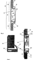
In
In
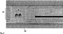
In
Erfindungsgemäß sind zur Realisierung des ersten und zweiten Abdeckelements
Gemäß beiden Ausführungsvarianten umfasst das Strukturelement
Erfindungsgemäß ist es besonders vorteilhaft möglich, dass der Aufnahmebereich
In allen Ausführungsvarianten ist es erfindungsgemäß vorgesehen, dass die Abdeckelemente (d. h. das dritte Abdeckelement
Hinsichtlich der Befestigung des dritten Abdeckelements
Wie in
Gemäß der zweiten Ausführungsvariante (
Es ist erfindungsgemäß möglich, unterhalb des ersten Abdeckelements ein zusätzliches Kabel und/oder unterhalb des zweiten Abdeckelements ein weiteres zusätzliches Kabel zu führen. Dies ist in
ZITATE ENTHALTEN IN DER BESCHREIBUNG QUOTES INCLUDE IN THE DESCRIPTION
Diese Liste der vom Anmelder aufgeführten Dokumente wurde automatisiert erzeugt und ist ausschließlich zur besseren Information des Lesers aufgenommen. Die Liste ist nicht Bestandteil der deutschen Patent- bzw. Gebrauchsmusteranmeldung. Das DPMA übernimmt keinerlei Haftung für etwaige Fehler oder Auslassungen.This list of the documents listed by the applicant has been generated automatically and is included solely for the better information of the reader. The list is not part of the German patent or utility model application. The DPMA assumes no liability for any errors or omissions.
Zitierte PatentliteraturCited patent literature
- DE 102005022441 A1 [0004] DE 102005022441 A1 [0004]
Claims (10)
Priority Applications (1)
| Application Number | Priority Date | Filing Date | Title |
|---|---|---|---|
| DE201220003473 DE202012003473U1 (en) | 2012-04-05 | 2012-04-05 | Mounting system, in particular for mounting on a provided with a mineral surface clothing wall |
Applications Claiming Priority (1)
| Application Number | Priority Date | Filing Date | Title |
|---|---|---|---|
| DE201220003473 DE202012003473U1 (en) | 2012-04-05 | 2012-04-05 | Mounting system, in particular for mounting on a provided with a mineral surface clothing wall |
Publications (1)
| Publication Number | Publication Date |
|---|---|
| DE202012003473U1 true DE202012003473U1 (en) | 2013-07-08 |
Family
ID=48951070
Family Applications (1)
| Application Number | Title | Priority Date | Filing Date |
|---|---|---|---|
| DE201220003473 Expired - Lifetime DE202012003473U1 (en) | 2012-04-05 | 2012-04-05 | Mounting system, in particular for mounting on a provided with a mineral surface clothing wall |
Country Status (1)
| Country | Link |
|---|---|
| DE (1) | DE202012003473U1 (en) |
Cited By (2)
| Publication number | Priority date | Publication date | Assignee | Title |
|---|---|---|---|---|
| CN105421727A (en) * | 2015-08-31 | 2016-03-23 | 嘉兴云木环保科技有限公司 | Decorative moulding, closing component and decorative moulding assembly |
| DE202017105453U1 (en) * | 2017-09-08 | 2018-12-13 | REHAU Gesellschaft m.b.H | Wall connection system |
Citations (1)
| Publication number | Priority date | Publication date | Assignee | Title |
|---|---|---|---|---|
| DE102005022441A1 (en) | 2005-05-14 | 2006-11-16 | Abb Patent Gmbh | Channel socket outlet fixture system e.g., for electrical installation appliances, has rotational element arranged between clamping jaws |
-
2012
- 2012-04-05 DE DE201220003473 patent/DE202012003473U1/en not_active Expired - Lifetime
Patent Citations (1)
| Publication number | Priority date | Publication date | Assignee | Title |
|---|---|---|---|---|
| DE102005022441A1 (en) | 2005-05-14 | 2006-11-16 | Abb Patent Gmbh | Channel socket outlet fixture system e.g., for electrical installation appliances, has rotational element arranged between clamping jaws |
Cited By (3)
| Publication number | Priority date | Publication date | Assignee | Title |
|---|---|---|---|---|
| CN105421727A (en) * | 2015-08-31 | 2016-03-23 | 嘉兴云木环保科技有限公司 | Decorative moulding, closing component and decorative moulding assembly |
| CN105421727B (en) * | 2015-08-31 | 2018-08-21 | 浙江云木新材股份有限公司 | Moulding, closure and moulding component |
| DE202017105453U1 (en) * | 2017-09-08 | 2018-12-13 | REHAU Gesellschaft m.b.H | Wall connection system |
Similar Documents
| Publication | Publication Date | Title |
|---|---|---|
| EP2768342B1 (en) | Arrangement with a connecting apparatus for connecting two drawer wall parts which are arranged at a right angle | |
| DE102013100435A1 (en) | Connecting element for a conductor rail, conductor rail and method for producing a conductor rail | |
| EP2591181B1 (en) | Perforated gypsum-based boards and method for laying the same | |
| EP2639904B1 (en) | Equipment installation channel and method for the wall mounting of an equipment mounting channel | |
| EP3967828A1 (en) | Fastening system for cladding elements | |
| DE202012003473U1 (en) | Mounting system, in particular for mounting on a provided with a mineral surface clothing wall | |
| DE202010010424U1 (en) | Wall feed-through terminal for electrical conductors | |
| DE202014105219U1 (en) | Grounding rail device | |
| DE102012006915A1 (en) | Mounting system, in particular for mounting on a wall provided with a mineral surface clothing, method for assembling a mounting system and method for retrofitting a socket fastening element ... | |
| EP2523281B1 (en) | Cable channel | |
| DE102011085396A1 (en) | Fastening arrangement for plate-shaped lining components, trim arrangement and aircraft or spacecraft | |
| DE102012107751A1 (en) | Power bus bar for use in interior of switch cabinet, has supporting structure that is accommodated in cavity formed in conductor of bus bar, to support wall elements against each other | |
| EP2639910B1 (en) | Device installation socket for device installation channels and equipment installation channel comprising same | |
| DE102012217815B4 (en) | duct | |
| DE202012003476U1 (en) | Mounting system, in particular for mounting on a wall | |
| DE102012006917A1 (en) | Mounting system, in particular for mounting on a wall, method for mounting a mounting system and method for retrofitting a socket-mounting element | |
| DE202013100223U1 (en) | Connection element for a conductor rail, construction kit for a conductor rail and conductor rail | |
| DE202013008101U1 (en) | Mounting system, in particular for mounting on a provided with a mineral surface clothing wall | |
| DE202012003472U1 (en) | Surface covering edge rail for edge termination of a mineral surface clothing, in particular for mounting on a provided with a mineral surface clothing mounting surface, structural element, cover | |
| DE202017102580U1 (en) | frame element | |
| DE102021126007A1 (en) | grommet | |
| EP3217497A1 (en) | Device holder | |
| DE202011001159U1 (en) | Wall or ceiling holder for a suspension system | |
| DE102012205614B4 (en) | bus | |
| DE202013100503U1 (en) | End profile for wall insulation |
Legal Events
| Date | Code | Title | Description |
|---|---|---|---|
| R207 | Utility model specification |
Effective date: 20130829 |
|
| R082 | Change of representative |
Representative=s name: KUTZENBERGER WOLFF & PARTNER PATENTANWALTSPART, DE |
|
| R081 | Change of applicant/patentee |
Owner name: DURAL GMBH, DE Free format text: FORMER OWNER: DURAL GMBH & CO. KG, 56412 RUPPACH-GOLDHAUSEN, DE Effective date: 20140819 |
|
| R082 | Change of representative |
Representative=s name: KUTZENBERGER WOLFF & PARTNER PATENTANWALTSPART, DE Effective date: 20140819 |
|
| R156 | Lapse of ip right after 3 years |