DE202022106295U1 - Improved Fluid Level Gauge for a Work Vehicle - Google Patents
Improved Fluid Level Gauge for a Work Vehicle Download PDFInfo
- Publication number
- DE202022106295U1 DE202022106295U1 DE202022106295.1U DE202022106295U DE202022106295U1 DE 202022106295 U1 DE202022106295 U1 DE 202022106295U1 DE 202022106295 U DE202022106295 U DE 202022106295U DE 202022106295 U1 DE202022106295 U1 DE 202022106295U1
- Authority
- DE
- Germany
- Prior art keywords
- fluid level
- reservoir
- level indicator
- fluid
- inclination
- Prior art date
- Legal status (The legal status is an assumption and is not a legal conclusion. Google has not performed a legal analysis and makes no representation as to the accuracy of the status listed.)
- Active
Links
Images


Classifications
-
- G—PHYSICS
- G01—MEASURING; TESTING
- G01F—MEASURING VOLUME, VOLUME FLOW, MASS FLOW OR LIQUID LEVEL; METERING BY VOLUME
- G01F23/00—Indicating or measuring liquid level or level of fluent solid material, e.g. indicating in terms of volume or indicating by means of an alarm
- G01F23/02—Indicating or measuring liquid level or level of fluent solid material, e.g. indicating in terms of volume or indicating by means of an alarm by gauge glasses or other apparatus involving a window or transparent tube for directly observing the level to be measured or the level of a liquid column in free communication with the main body of the liquid
Landscapes
- Physics & Mathematics (AREA)
- Fluid Mechanics (AREA)
- General Physics & Mathematics (AREA)
- Cooling, Air Intake And Gas Exhaust, And Fuel Tank Arrangements In Propulsion Units (AREA)
- Measurement Of Levels Of Liquids Or Fluent Solid Materials (AREA)
- Level Indicators Using A Float (AREA)
Abstract
Fluidpegelanzeige (6) zum Anzeigen des Pegels eines Fluids, das in einem Fahrzeugvorratsbehälter (4) enthalten ist, wobei die Fluidpegelanzeige (6) ein hohles Element (7) umfasst, das sich entlang einer Längsachse (A) erstreckt und konfiguriert ist, mit dem Vorratsbehälter (4) fluidtechnisch verbunden zu sein, wobei das hohle Element (7) Anzeigemittel (13) umfasst, die konfiguriert sind, das Prüfen eines Fluidpegels im Vorratsbehälter (4) zu ermöglichen, wobei die Fluidpegelanzeige (6) ferner Neigungssensormittel (15) umfasst, die durch das hohle Element (7) getragen werden und konfiguriert sind, das Prüfen der Neigung des Vorratsbehälters (4) in Bezug auf den Boden (G) zu ermöglichen.

Description
Technisches Gebiettechnical field
Die vorliegende Erfindung betrifft eine Fluidpegelanzeige, insbesondere eine Fluidpegelanzeige für ein Arbeitsfahrzeug.The present invention relates to a fluid level gauge, particularly to a fluid level gauge for a work vehicle.
Die vorliegende Erfindung findet ihre bevorzugte, jedoch nicht exklusive Anwendung in landwirtschaftlichen Fahrzeugen. Auf diese Anwendung wird unten auf beispielhafte Weise Bezug genommen.The present invention finds its preferred, but not exclusive, application in agricultural vehicles. This application is referred to below in an exemplary manner.
Hintergrund der ErfindungBackground of the Invention
Arbeitsfahrzeuge wie etwa landwirtschaftliche Fahrzeuge sind mit mehreren Vorratsbehältern versehen, die konfiguriert sind, ein Arbeitsfluid des Fahrzeugs zu speichern.Work vehicles such as agricultural vehicles are provided with multiple reservoirs configured to store a working fluid of the vehicle.
Insbesondere können Beispiele für ein derartiges Arbeitsfluid ein Hydrauliköl. das in hydraulischen Systemen des Fahrzeugs verwendet wird, oder Wasser/Fluidzusammensetzungen, die im Feld verwendet werden, sein.In particular, examples of such a working fluid can be a hydraulic oil. used in vehicle hydraulic systems or water/fluid compositions used in the field.
Eine wirtschaftliche und bekannte Weise, den Pegel eines Arbeitsfluids in einem Vorratsbehälter visuell zu detektieren, ist die Verwendung einer Fluidpegelanzeige wie etwa eines Schauglases.An economical and known way to visually detect the level of a working fluid in a reservoir is to use a fluid level indicator such as a sight glass.
Ein Schauglas umfasst einen hohlen Zylinder aus durchsichtigem Material, der mit dem Vorratsbehälter fluidtechnisch verbunden ist, um durch das darin enthaltene Fluid bis zu einer Höhe aufgefüllt zu werden, die eine Funktion des Fluidpegels im Vorratsbehälter ist.A sight glass comprises a hollow cylinder of transparent material which is fluidly connected to the reservoir for being filled by the fluid contained therein to a level which is a function of the fluid level in the reservoir.
Das Schauglas umfasst eine Pegelskala auf seiner Außenfläche, die dem Fahrzeugbenutzer ermöglicht, die Fluidmenge, die im Vorratsbehälter gespeichert ist, abzurufen, um zu bewerten, ob ein Auffüllen des Vorratsbehälters notwendig ist.The sight glass includes a level scale on its outer surface that allows the vehicle user to view the amount of fluid stored in the reservoir to assess whether the reservoir needs topping up.
Wenn sich das Fahrzeug jedoch auf einem geneigten Boden befindet, wird das Flüssigkeitsvolumen im Vorratsbehälter verlagert, wodurch eine Veränderung des Pegels, der über das Schauglas abgelesen werden kann, bewirkt wird. Ein ähnlicher Zustand kann auftreten, wenn das Fahrzeug auf eine Weise beladen ist, derart, dass sein Körper auf einer Seite stärker als auf der anderen geneigt ist.However, when the vehicle is on a sloping ground, the volume of liquid in the reservoir will shift, causing the level that can be read through the sight glass to change. A similar condition can occur when the vehicle is loaded in such a way that its body is tilted more on one side than the other.
Dementsprechend kann der Fahrzeugbenutzer den tatsächlichen Fluidpegel in einem Vorratsbehälter aufgrund einer Neigung des Bodens überschätzen oder unterschätzen.Accordingly, the vehicle operator may overestimate or underestimate the actual level of fluid in a reservoir due to a slope of the ground.
Daher wird die Notwendigkeit empfunden, das richtige Ablesen eines Fluidpegels über ein Schauglas zu verbessern, um eine Überschätzung oder Unterschätzung des Fluidpegels zu vermeiden.Therefore, a need is felt to improve the correct reading of a fluid level through a sight glass to avoid overestimating or underestimating the fluid level.
Eine Aufgabe der vorliegenden Erfindung ist, die oben genannten Notwendigkeiten auf eine kostengünstige und optimierte Weise zu befriedigen.An object of the present invention is to satisfy the above needs in a cheap and optimized way.
Zusammenfassung der ErfindungSummary of the Invention
Die oben genannte Aufgabe wird gelöst durch eine Fluidpegelanzeige 6 zum Anzeigen des Pegels eines Fluids, das in einem Fahrzeugvorratsbehälter 4 enthalten ist, wobei die Fluidpegelanzeige 6 ein hohles Element 7 umfasst, das sich entlang einer Längsachse A erstreckt und konfiguriert ist, mit dem Vorratsbehälter 4 fluidtechnisch verbunden zu sein, wobei das hohle Element 7 Anzeigemittel 13 umfasst, die konfiguriert sind, das Prüfen des Fluidpegels im Vorratsbehälter 4 zu ermöglichen, wobei die Fluidpegelanzeige 6 ferner Neigungssensormittel 15 umfasst, die durch das hohle Element 7 getragen werden und konfiguriert sind, das Prüfen der Neigung des Vorratsbehälters 4 in Bezug auf den Boden G zu ermöglichen.The above object is achieved by a
Insbesondere umfasst das Neigungssensormittel 15 mindestens ein Wasserwagen-Messgerät 16, das konfiguriert ist, die Neigung bezüglich der Längsachse A und/oder einer Querachse B davon zu prüfen.In particular, the inclination sensor means 15 comprises at least one
Außerdem umfasst das Neigungssensormittel 15 ein kreisförmiges Wasserwagen-Messgerät 16, das konfiguriert ist, das Prüfen der Neigung bezüglich der Längsachse A und einer Querachse B davon zu ermöglichen.In addition, the inclination sensor means 15 comprises a
Ferner weist das hohle Element 7 eine zylindrische Form auf und kann über ein oberes und ein unteres Verteilerrohr 8, 9 mit dem Vorratsbehälter 4 fluidtechnisch verbunden sein. Stärker bevorzugt ist das hohle Element 7 in einem durchsichtigen Material realisiert.Further, the
Außerdem umfasst das hohle Element 7 einen oberen und einen unteren Abschlussabschnitt 11, 12 entlang der Längsachse, wobei der obere und der untere Abschlussabschnitt 11, 12 konfiguriert sind, wahlweise an einem Hauptkörper 7a des hohlen Elements 7 arretiert zu sein.In addition, the
Vorzugsweise umfasst das Anzeigemittel 13 eine Skala 14, die auf dem hohlen Element 7 realisiert ist.Preferably, the display means 13 comprises a
Die Erfindung bezieht sich ferner auf ein Arbeitsfahrzeug 1, das einen Körper 2, der auf dem Boden G beweglich getragen wird, und mindestens einen Vorratsbehälter 4, der durch den Körper 2 getragen wird, umfasst, wobei das Arbeitsfahrzeug 1 eine Fluidpegelanzeige 6, wie oben zusammengefasst, die mit dem Vorratsbehälter 4 fluidtechnisch verbunden ist, umfasst.The invention further relates to a work vehicle 1 comprising a
Figurenlistecharacter list
Für ein besseres Verständnis der vorliegenden Erfindung wird im Folgenden eine bevorzugte Ausführungsform mittels eines nicht einschränkenden Beispiels unter Bezugnahme auf die beigefügten Zeichnungen beschrieben; es zeigen:
-
1 eine schematische Ansicht eines Fahrzeugs, das eine Fluidpegelanzeige gemäß der vorliegenden Erfindung umfasst; -
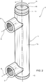
2 eine perspektivische Ansicht einer Fluidpegelanzeige gemäß der Erfindung, -
3 eine Stirnansicht der Fluidpegelanzeige aus2 ; -
4 eine Seitenansicht der Fluidpegelanzeige aus2 ; und -
5 eine Draufsicht der Fluidpegelanzeige aus2 .
-
1 Figure 12 is a schematic view of a vehicle including a fluid level gauge according to the present invention; -
2 a perspective view of a fluid level indicator according to the invention, -
3 Figure 1 shows an end view of thefluid level gauge 2 ; -
4 Figure 1 shows a side view of thefluid level gauge 2 ; and -
5 Figure 1 shows a top view of thefluid level gauge 2 .
Genaue Beschreibung der ErfindungDetailed description of the invention
Das Arbeitsfahrzeug 1 umfasst mindestens einen Vorratsbehälter 4 zum Speichern eines Arbeitsfluids, das durch das Arbeitsfahrzeug 1 für einen Vorgang verwendet wird. Nicht einschränkende Beispiele für den Vorratsbehälter 4 können Öltanks, Harnstoffvorratsbehälter, Wasserbehälter, landwirtschaftliche Substanzen oder Arbeitssubstanzen, die auf Böden oder in der Luft verteilt werden sollen, sein.The work vehicle 1 includes at least one
Wie an sich bekannt ist, umfasst der Vorratsbehälter 4 mehrere Wände 4a, die ein Volumen definieren, das konfiguriert ist, das oben genannte Arbeitsfluid zu speichern. Der Vorratsbehälter 4 ist mit einem Einfüllabschnitt 5 versehen, der z. B. über ein Verteilerrohr 5a, das durch eine Kappe 5b abgedeckt ist, realisiert ist, der konfiguriert ist, das Befüllen des Vorratsbehälters 4 zu ermöglichen. Natürlich umfasst der Vorratsbehälter einen Auslassabschnitt (nicht gezeigt), aus dem das enthaltende Fluid zur Verwendung ausgelassen werden kann.As is known per se, the
Der Vorratsbehälter 4 wird auf feststehende Weise am Körper 1 getragen, d. h. die Wände 4a werden durch den Körper des Fahrzeugs auf steife Weise getragen, sie sind z. B. mittels Winkeln oder Gewindeelementen arretiert.The
Das Fahrzeug 1 umfasst ferner eine Fluidpegelanzeige 6 gemäß der vorliegenden Erfindung, eine derartige Fluidpegelanzeige 6 ist konfiguriert, mit dem Vorratsbehälter 4 fluidtechnisch verbunden zu sein, um das Ablesen des Pegels des Fluids darin zu ermöglichen, und ist ferner konfiguriert, den Grad der Neigung des Vorratsbehälters 4 des Fahrzeugs in Bezug auf den Boden G zu erfassen.The vehicle 1 further comprises a
Unter Bezugnahme auf
Es sei erwähnt, dass, wie in
Die Fluidpegelanzeige 6 umfasst ferner ein oberes Verteilerrohr 8 und ein unteres Verteilerrohr 9, die konfiguriert sind, einen unteren Abschnitt und einen oberen Abschnitt des Vorratsbehälters 4 mit einem unteren Abschnitt und einem oberen Abschnitt des hohlen Elements 7 fluidtechnisch zu verbinden. Vorzugsweise sind der Hauptkörper 7a des hohlen Elements 7 und die Verteilerrohre 8, 9 in einem Stück realisiert.The
Insbesondere erstrecken sich das obere und das untere Verteilerrohr 8, 9 entlang einer Querachse B, die vorteilhafterweise zur Längsachse A senkrecht, d. h. zum Boden G parallel, ist.In particular, the upper and
Das hohle Element 7 kann ferner ein Paar Abschlusskopfabschnitte 11, 12, umfassen, die wahlweise auf steife Weise am Hauptkörper 7a arretiert sind und konfiguriert sind, fallweise zum Zweck des Reinigens seines Innenabschnitts vom Hauptkörper 7a entfernt zu werden.The
Die Fluidpegelanzeige 6 umfasst ferner Anzeigemittel 13, die konfiguriert sind, das Ablesen eines Wertes des Pegels des Fluids im hohlen Element 7 zu ermöglichen. Ein derartiges Anzeigemittel 13 kann als eine Skala 14 realisiert sein, die auf der Außenfläche des hohlen Körpers entlang der Längsachse A aufgedruckt oder darin eingraviert ist.The
Die Fluidpegelanzeige 6 umfasst Neigungssensormittel 15, die konfiguriert sind, auf sichtbare Weise durch das hohle Element 7 getragen zu werden, und konfiguriert sind zu ermöglichen, dass der Benutzer die Neigung des hohlen Elements 7 in Bezug auf den Boden in Bezug auf die Längsachse A und/oder die Querachse B schätzt. Insbesondere ermöglichen die Neigungssensormittel 15 das Schätzen der Neigung bezüglich beider Achsen A, B.The
Vorzugsweise umfassen die Sensormittel 15 mindestens ein Wasserwagen-Messgerät 16, das durch das hohle Element 7 getragen wird, um die Schätzung der Neigung in Bezug auf die Achse A und/oder B zu ermöglichen.Preferably, the sensor means 15 comprise at least one
Im Einzelnen kann das Wasserwagen-Messgerät 16 ein kreisförmiges Wasserwagen-Messgerät sein, das auf der Oberseite des Hauptkörpers 4 getragen wird, das über ein einziges Element ermöglicht, die Neigung in Bezug auf die Achsen A und B zu schätzen. Dementsprechend wird das Wasserwagen-Messgerät 16 in diesem Fall durch den oberen Abschlussabschnitt 11 getragen, damit es für den Benutzer klar sichtbar ist.More specifically, the
Der Betrieb der oben beschriebenen Fluidpegelanzeige gemäß der Erfindung ist wie folgt.The operation of the fluid level indicator according to the invention described above is as follows.
Der Fahrer kann den Fluidpegel mittels der Skala 14 kontrollieren, die auf dem hohlen Element 7 aufgedruckt ist, und den Pegel des Fluids darin prüfen. Da die Verteilerrohre 8, 9 mit dem Vorratsbehälter 4 fluidtechnisch verbunden sind, füllt in der Tat derselbe Pegel des Fluids den Innenraum des hohlen Elements 7, wie bekannt ist.The driver can check the fluid level by means of the
Insbesondere kann der Fahrer außerdem die Neigungssensormittel 15 prüfen, um zu detektieren, ob das Fahrzeug 1 bzw. der Vorratsbehälter 4 in Bezug auf den Boden richtig angeordnet sind, d. h. ob das hohle Element 7 vertikal ist. Falls nicht, kann der Fahrer auf eine andere Weise das Fahrzeug 1 parken oder die Lasten darauf anordnen, um eine richtige Neigung der Fluidpegelanzeige 6 aufzuweisen.In particular, the driver can also check the inclination sensor means 15 in order to detect whether the vehicle 1 or the
Im Hinblick auf das Voranstehende sind die Vorteile einer Fluidpegelanzeige gemäß der Erfindung ersichtlich.In view of the foregoing, the advantages of a fluid level indicator according to the invention are evident.
Mittels der vorgeschlagenen Fluidpegelanzeige ist es möglich, sowohl den Fluidpegel zu prüfen als auch zu erfassen, ob das Fahrzeug bzw. der Vorratsbehälter in Bezug auf den Boden richtig angeordnet sind.By means of the proposed fluid level indicator it is possible both to check the fluid level and to detect whether the vehicle or the reservoir is positioned correctly in relation to the ground.
In der Tat ermöglicht die Verwendung der Neigungssensormittel, zumindest die richtige vertikale Orientierung des hohlen Elements 7 zu prüfen, derart, dass der Fahrer folgerichtige Korrekturmaßnahmen ergreifen kann.In fact, the use of the inclination sensor means makes it possible to check at least the correct vertical orientation of the
Im Einzelnen garantiert die Verwendung eines kreisförmigen Wasserwagen-Messgeräts, das die Prüfung der richtigen Position sowohl bezüglich der vertikalen Achse als auch der Querachse ermöglicht, eine sehr genaue und richtige Pegelmessung durch das Kontrollieren der richtigen Position bezüglich beider oben genannter Achsen.In particular, the use of a circular level gauge, which allows checking the correct position in both the vertical axis and the transverse axis, guarantees a very accurate and correct level measurement by checking the correct position in both the above axes.
Es ist eindeutig, dass an der beschriebenen Fluidpegelanzeige Modifikationen vorgenommen werden können, die sich nicht über den Schutzumfang, der durch die Ansprüche definiert ist, hinaus erstrecken.It is clear that modifications can be made to the fluid level indicator described which do not extend beyond the scope of protection defined by the claims.
Zum Beispiel können die Anzeigemittel 13 auf andere Weise realisiert sein, wie etwa die Pegelsensormittel 15.For example, the display means 13 can be realized in other ways, such as the level sensor means 15.
In der Tat können die Pegelsensormittel 15 mehrere Wasserwagen-Messgeräte oder eine andere Topologie eines Sensormittels umfassen.Indeed, the level sensor means 15 may comprise multiple level gauges or some other topology of sensor means.
Offensichtlich kann die Fluidpegelanzeige auf eine andere Weise realisiert sein, wie z. B. mittels eines hohlen Elements mit einer anderen Form, das ein einziges Verteilerrohr umfasst, wobei die hier beschriebenen Abschlussabschnitte nicht vorgesehen sindObviously the fluid level indicator can be realized in a different way, e.g. by means of a hollow member of a different shape, comprising a single manifold, without the termination portions described herein
Claims (9)
Applications Claiming Priority (2)
| Application Number | Priority Date | Filing Date | Title |
|---|---|---|---|
| IT202021000005312 | 2021-11-10 | ||
| IT202021000005312U IT202100005312U1 (en) | 2021-11-10 | 2021-11-10 | IMPROVED FLUID LEVEL INDICATOR FOR A WORK VEHICLE |
Publications (1)
| Publication Number | Publication Date |
|---|---|
| DE202022106295U1 true DE202022106295U1 (en) | 2022-11-28 |
Family
ID=84492294
Family Applications (1)
| Application Number | Title | Priority Date | Filing Date |
|---|---|---|---|
| DE202022106295.1U Active DE202022106295U1 (en) | 2021-11-10 | 2022-11-09 | Improved Fluid Level Gauge for a Work Vehicle |
Country Status (3)
| Country | Link |
|---|---|
| AT (1) | AT18024U1 (en) |
| DE (1) | DE202022106295U1 (en) |
| IT (1) | IT202100005312U1 (en) |
Family Cites Families (5)
| Publication number | Priority date | Publication date | Assignee | Title |
|---|---|---|---|---|
| US1979705A (en) * | 1929-11-26 | 1934-11-06 | Stanley Works | Airplane gasoline gauge |
| DE2628601A1 (en) * | 1976-06-25 | 1977-12-29 | Kloeckner Humboldt Deutz Ag | Compensated fuel and oil gauge for vehicles - has sight glass attached to swivel arm allowing for tank inclination |
| JP5545716B2 (en) * | 2009-12-24 | 2014-07-09 | いすゞ自動車株式会社 | Reducing agent tank structure |
| US9896132B1 (en) * | 2016-08-22 | 2018-02-20 | Komatsu Ltd. | Working vehicle |
| CN112697236A (en) * | 2020-12-24 | 2021-04-23 | 彩虹无人机科技有限公司 | Novel mark oil device of unmanned aerial vehicle |
-
2021
- 2021-11-10 IT IT202021000005312U patent/IT202100005312U1/en unknown
-
2022
- 2022-11-02 AT ATGM72/2022U patent/AT18024U1/en unknown
- 2022-11-09 DE DE202022106295.1U patent/DE202022106295U1/en active Active
Also Published As
| Publication number | Publication date |
|---|---|
| IT202100005312U1 (en) | 2023-05-10 |
| AT18024U1 (en) | 2023-11-15 |
Similar Documents
| Publication | Publication Date | Title |
|---|---|---|
| DE102014006695A1 (en) | Level sensor for level measurement and method for determining the level of a liquid | |
| EP2765398A1 (en) | Storage tank of an agricultural distribution machine with capacitative device for measuring the filling level | |
| DE3042693A1 (en) | LIQUID TANK FOR MASTER CYLINDER | |
| DE102016123489A1 (en) | level sensor | |
| DE102009049676A1 (en) | Device and method for level measurement in arbitrarily shaped containers, in particular within motor vehicle tanks | |
| EP1318966B1 (en) | Method and device for determining quantities of fluid | |
| DE102010011638A1 (en) | Capacitive level sensor and level detection method with a capacitive level sensor | |
| AT18024U1 (en) | Improved fluid level indicator for a work vehicle | |
| DE102015116748A1 (en) | FUEL LEVEL SENSOR | |
| DE4122288C2 (en) | Device for measuring a liquid level with a dipstick | |
| DE202004020113U1 (en) | Improved pressure reading design for a pressure gauge | |
| DE102013011665A1 (en) | Fuel tank for a motor vehicle and extradition procedure for a motor vehicle | |
| DE8805105U1 (en) | Test device for the battery and radiator fluid of a motor vehicle | |
| DE7609265U1 (en) | OIL LEVEL KNIFE FOR DISTANCE READING | |
| DE102016122298A1 (en) | Capacitive level sensing device distributor and method of operating the capacitive level sensing device | |
| DE19706869C2 (en) | Device for recording the fill quantities of liquids with solid contents such as faeces or chemical waste in tanks of tankers, especially suction tankers | |
| DE2813670C2 (en) | Mobile machine for applying and distributing flowable substances on or in the ground | |
| DE102021102510B3 (en) | Analog display device for displaying a quantity of liquid to be dispensed from a container | |
| EP2417334A1 (en) | Oil tank having improved readability of the fill level | |
| DE102004045149A1 (en) | Liquid level sensor, especially for measuring the amount of liquid in a windscreen wash reservoir, comprises a weighing device and an evaluation unit for determining the liquid level by weighing | |
| DE596682C (en) | Overflow device for pressure gauge | |
| DE1960648A1 (en) | Level meter | |
| DE102024119157B4 (en) | Expansion tank and vehicle | |
| CH620293A5 (en) | Filling level measuring device on a liquid tank. | |
| DE132575C (en) |
Legal Events
| Date | Code | Title | Description |
|---|---|---|---|
| R207 | Utility model specification | ||
| R150 | Utility model maintained after payment of first maintenance fee after three years |