DE4442425B4 - Combustion chamber of a burner for a vehicle heater or for an exhaust gas particle filter - Google Patents
Combustion chamber of a burner for a vehicle heater or for an exhaust gas particle filter Download PDFInfo
- Publication number
- DE4442425B4 DE4442425B4 DE4442425A DE4442425A DE4442425B4 DE 4442425 B4 DE4442425 B4 DE 4442425B4 DE 4442425 A DE4442425 A DE 4442425A DE 4442425 A DE4442425 A DE 4442425A DE 4442425 B4 DE4442425 B4 DE 4442425B4
- Authority
- DE
- Germany
- Prior art keywords
- combustion chamber
- lining
- chamber according
- boundary wall
- combustion
- Prior art date
- Legal status (The legal status is an assumption and is not a legal conclusion. Google has not performed a legal analysis and makes no representation as to the accuracy of the status listed.)
- Expired - Lifetime
Links
Classifications
-
- F—MECHANICAL ENGINEERING; LIGHTING; HEATING; WEAPONS; BLASTING
- F23—COMBUSTION APPARATUS; COMBUSTION PROCESSES
- F23M—CASINGS, LININGS, WALLS OR DOORS SPECIALLY ADAPTED FOR COMBUSTION CHAMBERS, e.g. FIREBRIDGES; DEVICES FOR DEFLECTING AIR, FLAMES OR COMBUSTION PRODUCTS IN COMBUSTION CHAMBERS; SAFETY ARRANGEMENTS SPECIALLY ADAPTED FOR COMBUSTION APPARATUS; DETAILS OF COMBUSTION CHAMBERS, NOT OTHERWISE PROVIDED FOR
- F23M9/00—Baffles or deflectors for air or combustion products; Flame shields
-
- F—MECHANICAL ENGINEERING; LIGHTING; HEATING; WEAPONS; BLASTING
- F01—MACHINES OR ENGINES IN GENERAL; ENGINE PLANTS IN GENERAL; STEAM ENGINES
- F01N—GAS-FLOW SILENCERS OR EXHAUST APPARATUS FOR MACHINES OR ENGINES IN GENERAL; GAS-FLOW SILENCERS OR EXHAUST APPARATUS FOR INTERNAL-COMBUSTION ENGINES
- F01N13/00—Exhaust or silencing apparatus characterised by constructional features
- F01N13/18—Construction facilitating manufacture, assembly, or disassembly
- F01N13/1861—Construction facilitating manufacture, assembly, or disassembly the assembly using parts formed by casting or moulding
- F01N13/1866—Construction facilitating manufacture, assembly, or disassembly the assembly using parts formed by casting or moulding the channels or tubes thereof being made integrally with the housing
-
- F—MECHANICAL ENGINEERING; LIGHTING; HEATING; WEAPONS; BLASTING
- F01—MACHINES OR ENGINES IN GENERAL; ENGINE PLANTS IN GENERAL; STEAM ENGINES
- F01N—GAS-FLOW SILENCERS OR EXHAUST APPARATUS FOR MACHINES OR ENGINES IN GENERAL; GAS-FLOW SILENCERS OR EXHAUST APPARATUS FOR INTERNAL-COMBUSTION ENGINES
- F01N3/00—Exhaust or silencing apparatus having means for purifying, rendering innocuous, or otherwise treating exhaust
- F01N3/02—Exhaust or silencing apparatus having means for purifying, rendering innocuous, or otherwise treating exhaust for cooling, or for removing solid constituents of, exhaust
- F01N3/021—Exhaust or silencing apparatus having means for purifying, rendering innocuous, or otherwise treating exhaust for cooling, or for removing solid constituents of, exhaust by means of filters
- F01N3/023—Exhaust or silencing apparatus having means for purifying, rendering innocuous, or otherwise treating exhaust for cooling, or for removing solid constituents of, exhaust by means of filters using means for regenerating the filters, e.g. by burning trapped particles
- F01N3/025—Exhaust or silencing apparatus having means for purifying, rendering innocuous, or otherwise treating exhaust for cooling, or for removing solid constituents of, exhaust by means of filters using means for regenerating the filters, e.g. by burning trapped particles using fuel burner or by adding fuel to exhaust
- F01N3/0253—Exhaust or silencing apparatus having means for purifying, rendering innocuous, or otherwise treating exhaust for cooling, or for removing solid constituents of, exhaust by means of filters using means for regenerating the filters, e.g. by burning trapped particles using fuel burner or by adding fuel to exhaust adding fuel to exhaust gases
- F01N3/0256—Exhaust or silencing apparatus having means for purifying, rendering innocuous, or otherwise treating exhaust for cooling, or for removing solid constituents of, exhaust by means of filters using means for regenerating the filters, e.g. by burning trapped particles using fuel burner or by adding fuel to exhaust adding fuel to exhaust gases the fuel being ignited by electrical means
-
- F—MECHANICAL ENGINEERING; LIGHTING; HEATING; WEAPONS; BLASTING
- F23—COMBUSTION APPARATUS; COMBUSTION PROCESSES
- F23D—BURNERS
- F23D3/00—Burners using capillary action
- F23D3/40—Burners using capillary action the capillary action taking place in one or more rigid porous bodies
-
- F—MECHANICAL ENGINEERING; LIGHTING; HEATING; WEAPONS; BLASTING
- F23—COMBUSTION APPARATUS; COMBUSTION PROCESSES
- F23M—CASINGS, LININGS, WALLS OR DOORS SPECIALLY ADAPTED FOR COMBUSTION CHAMBERS, e.g. FIREBRIDGES; DEVICES FOR DEFLECTING AIR, FLAMES OR COMBUSTION PRODUCTS IN COMBUSTION CHAMBERS; SAFETY ARRANGEMENTS SPECIALLY ADAPTED FOR COMBUSTION APPARATUS; DETAILS OF COMBUSTION CHAMBERS, NOT OTHERWISE PROVIDED FOR
- F23M5/00—Casings; Linings; Walls
-
- F—MECHANICAL ENGINEERING; LIGHTING; HEATING; WEAPONS; BLASTING
- F01—MACHINES OR ENGINES IN GENERAL; ENGINE PLANTS IN GENERAL; STEAM ENGINES
- F01N—GAS-FLOW SILENCERS OR EXHAUST APPARATUS FOR MACHINES OR ENGINES IN GENERAL; GAS-FLOW SILENCERS OR EXHAUST APPARATUS FOR INTERNAL-COMBUSTION ENGINES
- F01N2240/00—Combination or association of two or more different exhaust treating devices, or of at least one such device with an auxiliary device, not covered by indexing codes F01N2230/00 or F01N2250/00, one of the devices being
- F01N2240/14—Combination or association of two or more different exhaust treating devices, or of at least one such device with an auxiliary device, not covered by indexing codes F01N2230/00 or F01N2250/00, one of the devices being a fuel burner
-
- F—MECHANICAL ENGINEERING; LIGHTING; HEATING; WEAPONS; BLASTING
- F23—COMBUSTION APPARATUS; COMBUSTION PROCESSES
- F23D—BURNERS
- F23D2900/00—Special features of, or arrangements for burners using fluid fuels or solid fuels suspended in a carrier gas
- F23D2900/21—Burners specially adapted for a particular use
- F23D2900/21002—Burners specially adapted for a particular use for use in car heating systems
Landscapes
- Engineering & Computer Science (AREA)
- Chemical & Material Sciences (AREA)
- Combustion & Propulsion (AREA)
- Mechanical Engineering (AREA)
- General Engineering & Computer Science (AREA)
- Processes For Solid Components From Exhaust (AREA)
- Spray-Type Burners (AREA)
Abstract
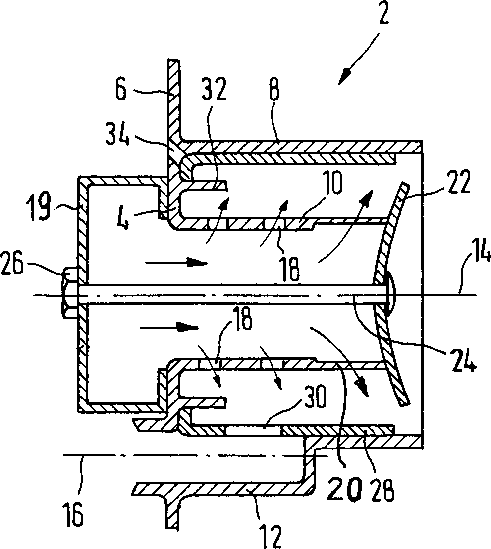
Brennkammer (2) eines Brenners für ein Fahrzeugheizgerät oder für thermische Regeneration eines Abgas-Partikelfilters, die eine Stirn-Begrenzungswand (4), eine Umfangs-Begrenzungswand (8), einen Stutzen (12) zur Unterbringung einer Glühkerze und einen Stutzen (10) zur Zuführung von Verbrennungsluft aufweist, der von der Stirn-Begrenzungswand (4) in die Brennkammer (2) ragt und mindestens Verbrennungsluftaustritte (18; 42) durch die Stutzenwand aufweist, dadurch gekennzeichnet, daß die Brennkammer (2) mit der Stirn-Begrenzungswand (4), mit der Umfangs-Begrenzungswand (8), mit dem Glühkerzen-Stutzen (12), und mit dem Luftzuführungs-Stutzen (10) als einstückiges Feingußbauteil ausgebildet ist.Combustion chamber (2) of a burner for a vehicle heater or for thermal regeneration of an exhaust gas particle filter, which has an end boundary wall (4), a circumferential boundary wall (8), a nozzle (12) for accommodating a glow plug and a nozzle (10) for supplying combustion air, which projects from the end wall (4) into the combustion chamber (2) and has at least combustion air outlets (18; 42) through the nozzle wall, characterized in that the combustion chamber (2) with the end wall ( 4), with the circumferential boundary wall (8), with the glow plug socket (12), and with the air supply socket (10) is formed as a one-piece investment casting component.
Description
Die Erfindung bezieht sich auf die Brennkammer eines Brenners für ein Fahrzeugheizgerät oder für thermische Regeneration eines Abgas-Partikelfilters, die eine Stirn-Begrenzungswand, eine Umfangs-Begrenzungswand, einen Stutzen zur Unterbringung einer Glühkerze und einen Stutzen zur Zuführung von Verbrennungsluft aufweist, der von der Stirn-Begrenzungswand in die Brennkammer ragt und mindestens Verbrennungsluftaustritte durch die Stutzenwand aufweist.The invention relates to the Combustion chamber of a burner for a vehicle heater or for thermal regeneration of an exhaust gas particle filter, which has an end boundary wall, a circumferential boundary wall, a nozzle for housing a glow plug and a nozzle for feeding of combustion air from the forehead boundary wall protrudes into the combustion chamber and at least combustion air exits through the nozzle wall.
Derartige Brennkammern von Brennern
für die
genannten Einsatzgebiete sind bekannt (
Der Erfindung liegt die Aufgabe zugrunde, eine rationeller herstellbare Brennkammer verfügbar zu machen.The invention has for its object a to make the combustion chamber more efficient to produce.
Zur Lösung dieser Aufgabe ist die Brennkammer mit der Stirn-Begrenzungswand, mit der Umfangs-Begrenzungswand, mit dem Glühkerzen-Stutzen, und mit dem Luftzuführungs-Stutzen als einstückiges Feingußbauteil ausgebildet.To solve this problem is the Combustion chamber with the end boundary wall, with the peripheral boundary wall, with the glow plug socket, and with the air supply nozzle as one piece Feingußbauteil educated.
Feingießen ist ein an sich bekanntes Herstellungsverfahren. Der Ausbildung einer Brennkammer als Feingußbauteil stand jedoch die auf dem Erfindungsgebiet allgemein verbreitete Auffassung der Fachwelt entgegen, daß nur die angesprochene "Blechbauweise" geeignet sei, Brennkammern aus geeigneten Werkstoffen und in der gewünschten dünnen Wandstärke der Bestandteile herstellen zu können. Die Erfinder des vorliegenden Erfindungsgegenstands haben sich über diese Bedenken hinweggesetzt und haben herausgefunden, daß nach dem Feingußverfahren wider Erwarten doch Brennkammern mit sinnvoll kleinen Wandstärken und aus geeignetem Material herstellbar sind. Die Herstellungsgenauigkeit ist ohne Nachrichtarbeiten besser als bei der Blechbauweise. Es sind höchstens minimale Nachbearbeitungen, z.B. Anbringen einer Brennstoffzuführungsbohrung, erforderlich.Investment casting is a well-known Production method. The formation of a combustion chamber as an investment casting stood, however, the one commonly used in the field of the invention Opposition of the professional world that only the "sheet metal construction" mentioned is suitable, combustion chambers Manufacture from suitable materials and in the desired thin wall thickness of the components to be able to. The inventors of the present subject matter have become aware of them Overruled concerns and found that after the investment casting process contrary to expectations, combustion chambers with sensibly small wall thicknesses and can be produced from a suitable material. The manufacturing accuracy is better without message work than with sheet metal construction. It are at most minimal post-processing, e.g. Drilling a fuel supply hole, required.
Die Erfindung gibt die Möglichkeit, die Feinguß-Integralbauweise der Brennkammer sehr weit oder weniger weit zu treiben. Durch Einbeziehung des Luftzuführungs-Stutzens in die Integralbauweise ergibt sich ein besonders hoher Rationalisierungseffekt. Aus der weiteren Beschreibung wird deutlich werden, daß man in Weiterbildung der Erfindung auch noch weitere Funktionsbestandteile der Brennkammer in die Feinguß-Integralbauweise einbeziehen kann.The invention gives the possibility the investment casting integral design to drive the combustion chamber very far or less. By including the Air supply nozzle The integral construction method has a particularly high rationalization effect. From the further description it will be clear that in Further development of the invention also further functional components the combustion chamber in the investment casting integral design can involve.
Ein typischer, bei der Erfindung bevorzugter Vertreter der Feingußtechnologie ist das an sich bekannte Wachsausschmelzverfahren. Bei diesem Verfahren wird zunächst eine Herstellungsform für ein Wachsmodell, welches die Gestalt des letztendlich herzustellenden Feingußbauteils hat, angefertigt. Eine größere Anzahl dieser Wachsmodelle wird dann, angeschlossen an einen gemeinsamen Eingießkanal, in ein – häufig aus keramischen Partikeln mit Bindemittel bestehendes – Formmaterial eingeformt. Beim anschließenden Gießen schmelzen die Wachsmodelle aus und werden die dadurch entstehenden Formhohlräume mit flüssigem Metall ausgefüllt. Zum Entformen der Feingußbauteile wird das Formmaterial zerstört.A typical one in the invention in itself, this is the preferred representative of investment casting technology known lost wax processes. In this process, a Production form for a wax model, which the shape of the ultimately to be manufactured Feingußbauteils has made. A larger number These wax models are then connected to a common one sprue, in one - often out ceramic particles with binder existing - molding material formed. At the subsequent to water melt the wax models and become the resultant mold cavities with liquid Filled in metal. For demoulding the investment cast components the molding material is destroyed.
Als Material für das erfindungsgemäße Feingußbauteil sind verzunderungsbeständige und hochwarmfeste Stahllegierungen bevorzugt, insbesondere Stahllegierungen aus der Gruppe der rostfreien Edelstähle.As a material for the investment casting component according to the invention are resistant to scaling and heat resistant steel alloys are preferred, especially steel alloys from the group of stainless steel.
Vorzugsweise ist der Glühkerzen-Stutzen mindestens im wesentlichen parallel zur Längserstreckungsrichtung der Brennkammer ausgerichtet und als Ausbuchtung der Umfangs-Begrenzungswand ausgebildet. Im Querschnitt kann die Ausbuchtung eine teilkreisförmige Gestalt haben, insbesondere eine im wesentlichen halbkreisförmige oder zwischen halbkreisförmig und dreiviertelkreisförmig liegende Gestalt haben. In Längserstreckungsrichtung ist der Glühkerzen-Stutzen normalerweise kürzer als die Umfangs-Begrenzungswand.Preferably, the glow plug socket is at least essentially parallel to the direction of longitudinal extension aligned the combustion chamber and formed as a bulge of the circumferential boundary wall. In cross section, the bulge can have a part-circular shape have, in particular a substantially semicircular or between semicircular and three-quarter circular have a lying shape. In the longitudinal direction is the glow plug socket usually shorter than the perimeter boundary wall.
Der Luftzuführungsstutzen kann an seinem strömungsabwärtigen Ende zum Inneren der Brennkammer offen sein (wodurch sich ein End-Verbrennungsluftaustritt ergibt) oder an diesem Ende auch geschlossen sein (so daß er nur die Verbrennungsluftaustritte durch die Stutzenwand aufweist). Im erstgenannten Fall ist es bevorzugt, strömungsabwärts von dem genannten offenen Ende einen Flammenhalter anzuordnen, der den aus dem offenen Ende austretenden Verbrennungsluftstrom nach außen in Richtung zu der Umfangs-Begrenzungswand verteilt, so daß er dort den Sauerstoff zum vollständigen Verbrennen des Brennstoffs liefert. Der Flammenhalter ist vorzugsweise eine zum Luftzuführungs-Stutzen hin konvex gekrümmte Platte. Der Flammenhalter kann ein gesondertes, nachträglich angebrachtes Bauteil sein, kann aber auch Bestandteil des weiter vorn angesprochenen Feingußbauteils sein.The air supply nozzle can at its downstream end be open to the interior of the combustion chamber (which creates a final combustion air outlet results) or be closed at this end (so that it only the combustion air exits through the nozzle wall). in the in the former case it is preferred to flow downstream of the said open one End to arrange a flame holder that the emerging from the open end Combustion air flow to the outside towards the circumferential boundary wall so that it is there the oxygen to complete Burning the fuel supplies. The flame holder is preferred one towards the air supply nozzle convex curved Plate. The flame holder can be a separate, retrofitted component be, but can also be part of the above Feingußbauteils his.
In vielen Fällen ist es wünschenswert, daß die Brennkammer einen Befestigungsflansch für ihre Befestigung in dem Gesamtbrenner aufweist, wobei der Befestigungsflansch in den meisten Fällen quer zur Längserstreckungsrichtung der Brennkammer verläuft. Vorzugsweise weist das angesprochene Feingußbauteil den Befestigungsflansch einstückig auf. Herstellungstechnisch ist es dabei am günstigsten, wenn der Befestigungsflansch mindestens im wesentlichen in Fortsetzung der Stirn-Begrenzungswand nach radial-außen liegt.In many cases it is desirable that the combustion chamber have a mounting flange for its mounting in the overall burner, the mounting flange in most cases transverse to the longitudinal direction of the combustion chamber runs. The investment casting component mentioned preferably has the fastening flange in one piece. From a manufacturing point of view, it is most favorable if the fastening flange is at least substantially in continuation of the end boundary wall radially outwards.
Bisher hat man den Luftzuführungs-Stutzen durchweg rohrförmig mit verteilten Lochungen in der Stutzenwand ausgebildet. Nach einem zweiten Aspekt der Erfindung weist der Luftzuführungs-Stutzen Längsschlitze in der Stutzenwand als Verbrennungsluftaustritte auf. Ein Teil der Längsschlitze oder alle Längsschlitze reichen bis zum strömungsabwärtigen Ende des Luftzuführungs-Stutzens. Die Längsschlitze sind bei der Feingußtechnologie deutlich einfacher herstellbar als bohrungsartige Öffnungen in der Stutzenwand. Das Vorsehen von Längsschlitzen schließt jedoch nicht aus, daß zusätzlich noch bohrungsartige Verbrennungsluftaustritte in der Stutzenwand vorhanden sind.So far, you have consistently the air supply nozzle tubular with distributed perforations in the nozzle wall. After one second aspect of the invention, the air supply nozzle has longitudinal slots in the nozzle wall as combustion air outlets. A part of longitudinal slots or all longitudinal slots extend to the downstream end of the air supply nozzle. The longitudinal slots are in investment casting technology much easier to manufacture than hole-like openings in the nozzle wall. However, the provision of longitudinal slots closes not from that in addition bore-like combustion air outlets in the nozzle wall are.
Es wird ausdrücklich darauf hingewiesen, daß die beschriebene Konfiguration des Luftzuführungs-Stutzens mit Längsschlitzen einerseits eine bevorzugte Weiterbildung des zuvor beschriebenen, ersten Aspekts der Erfindung ("Brennkammer in Feingußtechnologie") darstellt, insbesondere weil ein Luftzuführungs-Stutzen mit Längsschlitzen in Feingußtechnologie bequemer herstellbar ist, daß aber andererseits der beschriebene zweite Aspekt der Erfindung eine eigenständige Erfindung darstellt, die auch losgelöst von dem Gedanken der Feingußtechnologie technisch vorteilhaft verwirklichbar ist.It is expressly pointed out that the described Configuration of the air supply nozzle with longitudinal slots on the one hand, a preferred development of the first described above Aspect of the Invention ("Combustion Chamber in investment casting technology "), in particular because an air supply nozzle with longitudinal slots in investment casting technology is easier to manufacture, but on the other hand the described second aspect of the invention is an independent invention represents that also detached of the idea of precision casting technology is technically advantageous.
Ein Längsschlitz, mehrere Längsschlitze oder alle Längsschlitze können – gemessen in Umfangsrichtung des Luftzuführungs-Stutzens – eine über die Schlitzlängsrichtung konstant bleibende Breite besitzen. Es ist aber auch möglich, daß einer, mehrere oder alle Längsschlitze – gemessen in Umfangsrichtung des Luftzuführungs-Stutzens – eine über die Schlitzlängsrichtung zum strömungsabwärtigen Ende hin zunehmende Breite haben. Die letztgenannte Maßnahme führt zu dem willkommenen Ergebnis, daß am strömungsaufwärtigen Endbereich der Brennkammer relativ wenig Verbrennungsluft aus dem Luftzuführungs-Stutzen in den Brennraum der Brennkammer übertritt, während mehr zum strömungsabwärtigen Ende des Luftzuführungs-Stutzens eine relativ größere Verbrennungsluftmenge in den Verbrennungsraum der Brennkammer übertritt und dort für die vollständige Verbrennung der Verbrennungsluft zur Verfügung steht. Dies ist ein Beispiel für die Situation, daß man das strömungsabwärtige Ende des Luftzuführungs-Stutzens geschlossen ausbilden kann, weil genügend große Luftaustrittsquerschnitte im strömungsabwärtigen Endbereich des Luftzuführungs-Stutzens durch die Stutzenwand zur Verfügung stehen.One longitudinal slot, several longitudinal slots or all longitudinal slots can - measured in the circumferential direction of the air supply nozzle - one over the Slit longitudinally have constant width. But it is also possible that one or more or all longitudinal slots - measured in the circumferential direction of the air supply nozzle - one over the Slit longitudinally to the downstream end have increasing width. The latter measure leads to that welcome result that on upstream end region of the Combustion chamber relatively little combustion air from the air supply nozzle enters the combustion chamber of the combustion chamber while more to the downstream end of the air supply nozzle a relatively larger amount of combustion air enters the combustion chamber of the combustion chamber and there for complete combustion of the combustion air stands. This is an example of the situation that one the downstream end of the air supply spigot closed can because enough size Air outlet cross sections in the downstream end area of the Air supply nozzle through the nozzle wall stand.
In bevorzugter Weiterbildung der Erfindung ist mindestens einer der Verbrennungsluftaustritte durch die Stutzenwand derart ausgebildet, daß die Verbrennungsluft mit Strömungskomponente in Umfangsrichtung des Luftzuführungs-Stutzens ausströmt. Hiermit erreicht man – für den Ablauf der Verbrennung des Brennstoffs in der Brennkammer günstig – einen Austritt der Verbrennungsluft nicht im wesentlichen in radialer Richtung, sondern mit mehr oder weniger stark ausgeprägter Strömungskomponente in Umfangsrichtung, so daß sich in dem Verbrennungsraum eine Drallströmung ergibt.In a preferred further education of Invention is at least one of the combustion air outlets the nozzle wall formed such that the combustion air with flow component in the circumferential direction of the air supply nozzle flows. With this you reach - for the process the combustion of fuel in the combustion chamber cheap - one Combustion air does not exit essentially radially Direction, but with a more or less pronounced flow component in the circumferential direction, so that results in a swirl flow in the combustion chamber.
Es ist ferner bevorzugt, den Luftzuführungs-Stutzen mit einem sich in Strömungsrichtung verjüngenden Innenquerschnitt auszubilden. Hierdurch wird den heißen, expandierenden Verbrennungsgasen im ringförmigen Verbrennungsraum zwischen der Umfangs-Begrenzungswand und dem Luftzuführungs-Stutzen ein in Strömungsrichtung zunehmender Strömungsquerschnitt zur Verfügung gestellt.It is further preferred to use the air supply nozzle with a tapering in the direction of flow Form internal cross-section. This will make the hot, expanding Combustion gases in the ring Combustion chamber between the peripheral boundary wall and the air supply nozzle one in the direction of flow increasing flow cross-section to disposal posed.
Die erfindungsgemäße Brennkammer ist vorzugsweise als Verdampfungsbrennkammer ausgebildet. Zu diesem Zweck kann man innen an der Stirn-Begrenzungswand und/oder der Umfangs-Begrenzungswand eine poröse Auskleidung zum Abdampfen des Brennstoffs vorsehen. Die Auskleidung muß nicht die Stirn-Begrenzungswand und/oder die Umfangs-Begrenzungswand vollständig überdecken. Poröse Auskleidung kann, muß aber nicht, auch im Inneren des Glühkerzen-Stutzens vorgesehen sein. Herkömmliche Materialien für die poröse Auskleidung sind Faservliese, insbesondere aus keramischen Fasern, oder Fasermetallwerkstoffe. Es versteht sich, daß der porösen Auskleidung von der Außenseite her Brennstoff zugeführt wird, der von der Auskleidung in den Verbrennungsraum hinein abdampft.The combustion chamber according to the invention is preferred designed as an evaporation combustion chamber. For this purpose you can on the inside of the end boundary wall and / or the circumferential boundary wall porous Provide a lining to evaporate the fuel. The lining does not have to the forehead boundary wall and / or completely cover the circumferential boundary wall. Porous lining can, but must not, even inside the glow plug socket be provided. conventional Materials for the porous lining are non-woven fabrics, especially made of ceramic fibers, or fiber metal materials. It is understood that the porous Lining from the outside forth fuel supplied which evaporates from the lining into the combustion chamber.
Nach einem dritten Aspekt der Erfindung ist eine Brennkammer vorgesehen, deren Auskleidung aus Sintermetall besteht. Dieser dritte Aspekt der Erfindung stellt einerseits eine bevorzugte Ausgestaltung der zuvor beschriebenen Erfindung dar, stellt aber andererseits auch eine selbständige Erfindung dar, die losgelöst von der im kennzeichnenden Teil des Anspruchs 1 angegebenen Feingußbauteil-Technologie vorteilhaft verwirklichbar ist. Eine poröse Auskleidung aus Sintermetall ist wesentlich dauerhafter als ein keramisches Faservlies, kann mit sehr gleichmäßiger Porosität und hoher Paßgenauigkeit hergestellt werden, und liefert einen optimalen Wandkontakt zu der betreffenden Brennkammerwand. Ferner ist es möglich, für die Auskleidung einen gleichen oder einen ähnlichen Werkstoff wie für die restlichen Funktionsbestandteile der Brennkammer einzusetzen, so daß das Recyceln der Brennkammer erleichtert ist. Schließlich kann man bequem die Dicke der Auskleidung von Ort zu Ort nach Bedarf variieren.According to a third aspect of the invention a combustion chamber is provided, the lining of which is made of sintered metal consists. On the one hand, this third aspect of the invention represents a preferred embodiment of the invention described above, on the other hand, it also represents an independent invention, detached from the investment casting component technology specified in the characterizing part of claim 1 can be advantageously implemented. A porous lining made of sintered metal is much more durable than a ceramic nonwoven, can with very uniform porosity and high Made fit be, and provides an optimal wall contact to the concerned Combustion chamber wall. It is also possible for the Lining the same or a similar material as for the remaining functional components the combustion chamber so that the recycling of the combustion chamber is relieved. Finally one can conveniently change the thickness of the liner from place to place as needed vary.
Nach einer bevorzugten Weiterbildung der Erfindung kann die Sintermetall-Auskleidung in situ in der Brennkammer erzeugt werden, indem man das Material der Auskleidung, d.h. die zu versinternden Partikel, im ungesinterten Zustand in die Brennkammer einbringt und dort an Ort und Stelle verhinter. Normalerweise wird für diesen Zweck ein Kern in die Brennkammer eingesetzt, so daß ein spaltförmiger Formgebungsraum zwischen der Stirn-Begrenzungswand bzw. der Umfangs-Begrenzungswand und dem Kern entsteht, in den die zu versinternden Partikel eingefüllt werden. Das Versintern erfolgt in üblicher Weise durch Wärmezufuhr. Das Versintern in situ liefert optimalen Kontakt zwischen der Auskleidung und der betreffenden Begrenzungswand der Brennkammer.According to a preferred development of the invention, the sintered metal lining can be produced in situ in the combustion chamber by inserting the material of the lining, ie the particles to be sintered, into the combustion chamber in the unsintered state always brings in and hides there on the spot. A core is normally inserted into the combustion chamber for this purpose, so that a gap-shaped shaping space is created between the end boundary wall or the peripheral boundary wall and the core, into which the particles to be sintered are filled. Sintering is carried out in the usual way by adding heat. Sintering in situ provides optimal contact between the lining and the relevant boundary wall of the combustion chamber.
Nach einem vierten Aspekt der Erfindung ist zwischen der Umfangs-Begrenzungswand und dem Luftzuführungs-Stutzen ein Leit- und Schutzring von der Stirn-Begrenzungswand aus ein Stück weit zum Inneren der Brennkammer ragend angeordnet. Der Leit- und Schutzring bewirkt eine mehr axiale Strömung der im strömungsaufwärtigen Endbereich aus dem Luftzuführungs-Stutzen austretenden Verbrennungsluft und – was besonders wichtig ist – verhindert ein Auftropfen von unverbranntem Brennstoff auf den im Betrieb heißen Luftzuführungs-Stutzen mit der erheblichen Gefahr der Verkokung des Luftzuführungs-Stutzens bis hin zum teilweisen oder vollständigen Verschließen von Verbrennungsluftaustritten, was die Gefahr nach sich zieht, daß die Verbrennung des Brennstoffs nicht mehr ordnungsgemäß abläuft.According to a fourth aspect of the invention is between the perimeter wall and the air supply nozzle a guide and protection ring from the front boundary wall a bit arranged projecting to the interior of the combustion chamber. The guide and protection ring causes a more axial flow that in the upstream end area from the air supply nozzle escaping combustion air and - which is particularly important - prevented a drop of unburned fuel on the hot air supply nozzle during operation with the considerable risk of coking of the air supply nozzle up to the partial or complete closure of Combustion air leaks, which entails the risk that the combustion of the Fuel no longer runs properly.
Es wird ausdrücklich darauf hingewiesen, daß dieser vierte Aspekt der Erfindung einerseits eine bevorzugte Ausgestaltung einzelner oder mehrerer der vorstehend beschriebenen Erfindungsaspekte darstellt, aber andererseits eine selbständige Erfindung, losgelöst vom im kennzeichnenden Teil des Anspruchs 1 angegebenen Feingußbauteil-Gedanken, darstellt, weil die Ausbildung gemäß dem vierten Aspekt der Erfindung auch unabhängig hiervon technisch vorteilhaft einsetzbar ist.It is expressly pointed out that this fourth aspect of the invention, on the one hand, a preferred embodiment one or more of the aspects of the invention described above represents, but on the other hand an independent invention, detached from im characterizing part of the investment casting component idea indicated, because training according to the fourth Aspect of the invention also independent of which is technically advantageous.
Der Leit- und Schutzring muß nicht unbedingt über 360° umlaufend sein. Bei geringeren Anforderungen kann es ausreichen, wenn er sich als Teilring über einen Teilumfang der Brennkammer erstreckt, insbesondere dort, wo mit einem Auftropfen von Brennstoff auf den Luftzuführungs-Stutzen am ehesten zu rechnen ist.The guide and protection ring does not have to absolutely about 360 ° all around his. With lower requirements, it can be sufficient if it is as a partial ring over extends a partial circumference of the combustion chamber, especially where with a drop of fuel on the air supply nozzle is most likely to be expected.
Der strömungsabwärtige Endbereich des Leit- und Schutzrings ist vorzugsweise so ausgebildet, daß er turbulenzsteigernd auf die Verbrennungsluftströmung wirkt, also die dortige Durchmischung von verdampftem Brennstoff und Verbrennungsluft fördert.The downstream end area of the guide and guard ring is preferably designed to increase turbulence on the combustion air flow works, i.e. the mixing of evaporated fuel there and promotes combustion air.
Die erfindungsgemäße Brennkammer kann – mit Ausnahme des Glühkerzen-Stutzens – im wesentlichen eine in Stirnansicht zylindrische Konfiguration aufweisen, muß es aber nicht zwingend.The combustion chamber according to the invention can - with one exception the glow plug neck - essentially have a cylindrical configuration in front view, but it must not necessarily.
Nach einem fünften Aspekt der Erfindung ist das der Stirn-Begrenzungswand der Brennkammer nähere Ende der Auskleidung und/oder das der Stirn-Begrenzungswand der Brennkammer entferntere Ende der Auskleidung in einem umfangsmäßig durchgehenden oder in Abschnitte unterbrochenen Ringspalt festgelegt. Aufgrund dieser Ausbildung läßt sich die Auskleidung produktionstechnisch äußerst einfach in der Brennkammer befestigen. Man kann so weit kommen, daß die Anzahl der bisher üblichen Schweißpunkte zur Befestigung der Auskleidung in der Brennkammer erheblich verringert werden kann oder auf Schweißpunkte ganz verzichtet werden kann. Zur Bildung des Ringspalts kann vorzugsweise ein umfangsmäßig durchgehender oder in Abschnitte unterbrochener Fixierring oder ein Bauteil vorgesehen sein, welches an einem die Brennkammer fortsetzenden Flammrohr befestigt ist.According to a fifth aspect of the invention this is the forehead boundary wall closer to the combustion chamber End of the lining and / or that of the forehead boundary wall Combustion chamber distant end of the liner in a circumferentially continuous or defined in sections interrupted annular gap. by virtue of this training can the lining is extremely simple in terms of production technology in the combustion chamber Fasten. One can go so far that the number of usual welding spots considerably reduced for fastening the lining in the combustion chamber can be or on spot welds can be dispensed with entirely. A can preferably be used to form the annular gap circumferentially continuous or provided in sections interrupted fixing ring or a component be attached to a flame tube continuing the combustion chamber is.
Es wird ausdrücklich darauf hingewiesen, daß dieser fünfte Aspekt der Erfindung einerseits eine bevorzugte Ausgestaltung einzelner oder mehrerer der vorstehend beschriebenen Erfindungsaspekte darstellt, aber andererseits eine selbständige Erfindung darstellt, losgelöst vom im kennzeichnenden Teil des Anspruchs 1 angegebenen Feingußbauteilgedanken, weil die Ausbildung gemäß dem fünften Aspekt der Erfindung auch unabhängig hiervon technisch vorteilhaft verwirklichbar ist.It is expressly pointed out that this fifth Aspect of the invention on the one hand a preferred embodiment of individual represents one or more of the inventive aspects described above, but on the other hand an independent invention represents detached from the investment casting component idea specified in the characterizing part of claim 1, because the training according to the fifth aspect the invention also independent of which is technically advantageous.
Vorzugweise ist der Fixierring für das der Stirn-Begrenzungswand nähere Ende der Auskleidung Bestandteil des Feingußbauteils. Die Lagefixierung der Auskleidung läßt sich dadurch perfektionieren, daß man den Fixierring mindestens an seinem freien Ende nach dem Einsetzen der Auskleidung auf die Auskleidung zu abbiegt, wodurch sich eine Festklemmung der Auskleidung ergibt. Zu diesem Zweck kann es günstig sein, den Fixierring an seinem freien Ende mit dünner Wandstärke auszubilden, damit er dort gut abgebogen werden kann. Das Abbiegen ist auch im Fall des in Abschnitte unterbrochenen Fixierrings besonders erleichtert.The fixing ring for the front wall is preferred details End of the lining part of the investment casting. The fixation the lining can be by perfecting that the fixing ring at least at its free end after insertion the liner turns towards the liner, causing a Clamping of the lining results. For this purpose, it may be convenient form the fixing ring at its free end with a thin wall so that it is there can be turned well. The turning is also in the case of the Sections of interrupted fixation ring particularly easy.
Das Einsetzen des Endes der Auskleidung in den ringspaltartigen Raum gestaltet sich besonders einfach, wenn – im Längsschnitt gesehen – sich dieser Raum zu seinem Abschlußende hin verjüngt und/oder die Auskleidung ein sich verjüngendes Ende aufweist. Es ist gerade bei der Befestigung der Auskleidung gemäß dem fünften Aspekt der Erfindung besonders bevorzugt, die Auskleidung nur an der Umfangs-Begrenzungswand der Brennkammer vorzusehen, so daß die Auskleidung insgesamt eine röhrenartige und nicht eine topfförmige Konfiguration hat.Inserting the end of the liner in the annular gap-like space is particularly easy if - in longitudinal section seen - yourself this room to its final end tapered and / or the liner has a tapered end having. It is precisely when the lining is attached according to the fifth aspect the invention particularly preferred, the lining only on the circumferential boundary wall Provide combustion chamber so that the Liner overall a tube-like and not a pot-shaped one Configuration.
Nach einem sechsten Aspekt der Erfindung weist die Umfangs-Begrenzungswand der Brennkammer innenseitig einen in Längserstreckungsrichtung der Brennkammer verlaufenden Vorsprung zur formschlüssigen Festlegung der Auskleidung gegenüber Bewegung in Umfangsrichtung auf. Auf diese Weise muß die Festlegung in Umfangsrichtung nicht von der restlichen Lagefixierung der Auskleidung geleistet werden. Außerdem wird erreicht, daß sich die Auskleidung nur in einer bestimmten Positionierung (bezogen auf Drehung um die Längsachse der Brennkammer) in die Brennkammer einbringen läßt, so daß z.B. eine Öffnung in der Auskleidung, die gegenüber dem Stutzen für die Glühkerze positioniert sein soll, selbsttätig an die richtige Stelle kommt.According to a sixth aspect of the invention, the circumferential boundary wall of the combustion chamber has on the inside a projection extending in the longitudinal direction of the combustion chamber for positively fixing the lining against movement in the circumferential direction. In this way, the determination in the circumferential direction does not have to be made by the remaining position fixing of the lining. In addition, it is achieved that the lining can only be introduced into the combustion chamber in a specific position (based on rotation about the longitudinal axis of the combustion chamber), so that, for example, an opening in the lining, the ge should be positioned opposite the nozzle for the glow plug, automatically comes to the right place.
Es wird ausdrücklich darauf hingewiesen, daß dieser sechste Aspekt der Erfindung einerseits eine bevorzugte Ausgestaltung einzelner oder mehrerer der vorstehend beschriebenen Erfindungsaspekte darstellt, aber andererseits eine selbständige Erfindung darstellt, losgelöst vom im kennzeichnenden Teil des Anspruchs 1 angegebenen Feingußbauteilgedanken, weil die Ausbildung gemäß dem sechsten Aspekt der Erfindung auch unabhängig hiervon technisch vorteilhaft verwirklichbar ist.It is expressly pointed out that this sixth aspect of the invention, on the one hand, a preferred embodiment one or more of the aspects of the invention described above represents but on the other hand represents an independent invention, detached from the investment casting component idea specified in the characterizing part of claim 1, because the training according to the sixth Aspect of the invention also independent of which is technically advantageous.
Nach einem siebten Aspekt der Erfindung ist im Strömungsweg der Verbrennungsluft vor dem Luftzuführungs-Stutzen eine Einrichtung zur Erzeugung von Strömungsdrall vorgesehen. Die drallbehaftete Verbrennungsluftströmung führt zu einer optimaleren Bildung eines verbrennungsgünstigen Brennstoff-Luft-Gemischs.According to a seventh aspect of the invention is in the flow path the combustion air in front of the air supply nozzle a device for generating flow swirl intended. The swirling combustion air flow leads to a optimal formation of a combustible fuel-air mixture.
Es wird ausdrücklich darauf hingewiesen, daß dieser siebte Aspekt der Erfindung einerseits eine bevorzugte Ausgestaltung einzelner oder mehrerer der vorstehend beschriebenen Erfindungsaspekte darstellt, aber andererseits eine selbständige Erfindung darstellt, losgelöst von im kennzeichnenden Teil des Anspruchs 1 angegebenen Feingußbauteilgedanken, weil die Ausbildung gemäß dem siebten Aspekt der Erfindung auch unabhängig hiervon technisch vorteilhaft verwirklichbar ist.It is expressly pointed out that this Seventh aspect of the invention is a preferred embodiment one or more of the aspects of the invention described above represents but on the other hand represents an independent invention, detached of investment casting component ideas specified in the characterizing part of claim 1, because training according to the seventh Aspect of the invention also independent of which is technically advantageous.
Vorzugsweise ist die Einrichtung zur Erzeugung von Strömungsdrall mindestens großenteils Bestandteil des Feingußbauteils oder mindestens großenteils Teil des Gehäuses eines der Brennkammer vorgesetzten Verbrennungsluftgebläses. Die Einrichtung kann insbesondere einen Leitapparat, einen am Umfang spiralartig begrenzten Strömungsraum oder dgl. aufweisen.Preferably the device for generating flow swirl at least for the most part Part of the investment casting component or at least for the most part Part of the housing one of the combustion air blowers in front of the combustion chamber. The facility can in particular a diffuser, a spiral on the circumference limited flow space or the like.
Nach einem achten Aspekt der Erfindung ist am Übergang zwischen der Umfangs-Begrenzungswand der Brennkammer und der Auskleidung ein Brennstoffverteilkanal vorgesehen, der sich mindestens über einen Teil des Umfangs der Umfangs-Begrenzungswand erstreckt. Durch den Brennstoffverteilkanal wird erreicht, daß sich der zugeführte Brennstoff bereits rückseitig von der Auskleidung über eine größere Fläche verteilt. Ein gleichmäßigeres Verdampfen des Brennstoffs über eine größere Fläche der Auskleidung und eine Verringerung der Gefahr des Abtropfens von Brennstoff von der Auskleidung sind die Folge.According to an eighth aspect of the invention is at the transition between the circumferential boundary wall of the combustion chamber and the liner a fuel distribution channel is provided, which is at least one Part of the circumference of the circumferential boundary wall extends. By the Fuel distribution channel is achieved that the fuel supplied already on the back from the lining over spread a larger area. A more even one Evaporation of the fuel over a larger area of the Lining and reducing the risk of draining The result is fuel from the lining.
Es wird ausdrücklich darauf hingewiesen, daß dieser achte Aspekt der Erfindung einerseits eine bevorzugte Ausgestaltung einzelner oder mehrerer der vorstehend beschriebenen Erfindungsaspekte darstellt, aber andererseits eine selbständige Erfindung darstellt, losgelöst vom im kennzeichnenden Teil des Anspruchs 1 angegebenen Feingußbauteilgedanken, weil die Ausbildung gemäß dem achten Aspekt der Erfindung auch unabhängig hiervon technisch vorteilhaft verwirklichbar ist.It is expressly pointed out that this eighth aspect of the invention on the one hand a preferred embodiment one or more of the aspects of the invention described above represents but on the other hand represents an independent invention, detached from the investment casting component idea specified in the characterizing part of claim 1, because the training according to the eighth Aspect of the invention also independent of which is technically advantageous.
Vorzugsweise ist ein in den Brennstoffverteilkanal mündender Brennstoffzuführungsstutzen zur Brennstoffzuführung im wesentlichen in Umfangsrichtung vorgesehen. Durch einen derartigen Brennstoffzuführungsstutzen wird die Erreichung der vorstehend abgehandelten Vorteile noch weiter gefördert.Preferably one is in the fuel distribution channel opening out Fuel supply connection for fuel supply provided essentially in the circumferential direction. By such Fuel supply connection the achievement of the advantages discussed above will go even further promoted.
Nach einem neunten Aspekt der Erfindung ist radial weiter außen als die Umfangs-Begrenzungswand der Brennkammer ein Wärmeleitfinger vorgesehen, dessen Ende in Längserstreckungsrichtung der Brennkammer weiter vorn als seine Wurzel liegt, und ist an der Außenseite des Brennkammerbauteils in demjenigen Bereich, wo an der Innenseite des Brennkammerbauteils die Wurzel des Wärmeleitfingers ist, ein Temperaturfühler angesetzt, mit dem sich erfassen läßt, ob in der Brennkammer Verbrennung abläuft oder nicht.According to a ninth aspect of the invention radially further out a heat conducting finger is provided as the peripheral boundary wall of the combustion chamber, its end in the longitudinal direction the combustion chamber is further forward than its root, and is at the outside of the combustion chamber component in the area where on the inside of the Combustion chamber component is the root of the thermal finger, a temperature sensor is attached, with which it can be determined whether in the combustion chamber combustion takes place or not.
Brenner für Fahrzeugheizgeräte oder für thermische Regeneration von Abgas-Partikelfiltern sind auch bisher in aller Regel mit einer sogenannten Flammerkennung bzw. Flammabbrucherkennung ausgerüstet. Wenn mit Hilfe dieser Einrichtung festgestellt wird, daß unbeabsichtigt in der Brennkammer noch kein Verbrennungsvorgang oder kein Verbrennungsvorgang mehr stattfindet, wird mindestens die Zufuhr von Brennstoff zu der Brennkammer unterbrochen, damit hier nicht unkontrollierte Ansammlungen von unverbranntem Brennstoff entstehen. Bisher hat man zu diesem Zweck normalerweise an der Wand des der Brennkammer nachgeordneten Wärmetauschers einen Temperaturfühler vorgesehen, der aufgrund absinkender Wandtemperatur den Flammabbruch erkennt. Diese Technik erfordert jedoch die Anbringung einer Bohrung durch die Außenwand des Wärmetauschers; insbesondere im Fall eines Verbrennungsgas/Wasser-Wärmetauschers ergeben sich Abdichtungs- und Korrosionsprobleme.Burners for vehicle heaters or for thermal So far, regeneration of exhaust gas particulate filters has been in everyone Usually equipped with a so-called flame detection or flame termination detection. If with the help of this facility it is found that unintentionally no combustion process or combustion process in the combustion chamber yet more takes place, at least the supply of fuel to the The combustion chamber is interrupted so that there are no uncontrolled accumulations of unburned fuel. So far you have for this purpose usually on the wall of the heat exchanger downstream of the combustion chamber a temperature sensor provided that the flame arrest due to falling wall temperature recognizes. However, this technique requires drilling a hole through the outer wall the heat exchanger; especially in the case of a combustion gas / water heat exchanger there are sealing and corrosion problems.
Gemäß dem neunten Aspekt der Erfindung wird der Anbringungort des Temperaturfühlers zu dem Brennkammerbauteil verlagert; es ergibt sich eine deutlich vereinfachte Herstellung, und Probleme der geschilderten Art werden vermieden. Vorzugsweise ist der Wärmeleitfinger Bestandteil des Feingußbauteils.According to the ninth aspect of the invention the location of the temperature sensor to the combustion chamber component relocated; there is a significantly simplified production, and problems of the kind described are avoided. Preferably is the thermal finger Part of the investment casting component.
Es wird ausdrücklich darauf hingewiesen, daß der neunte Aspekt der Erfindung einerseits eine bevorzugte Ausgestaltung einzelner oder mehrerer der vorstehend bechriebenen Erfindungsaspekte darstellt, aber andererseits eine selbständige Erfindung darstellt, losgelöst vom in kennzeichnenden Teil des Anspruchs 1 angegebenen Feingußbauteilgedanken, weil die Ausbildung gemäß dem neunten Aspekt der Erfindung auch unabhängig hiervon technisch vorteilhaft verwirklichbar ist.It is expressly pointed out that the ninth Aspect of the invention on the one hand a preferred embodiment of individual represents one or more of the inventive aspects described above, but on the other hand an independent one Invention represents detached from the investment casting component idea specified in the characterizing part of claim 1, because training according to the ninth Aspect of the invention also independent of which is technically advantageous.
Nach einem zehnten Aspekt der Erfindung ist von den Oberflächen, die im Betrieb zum Aufbau kohlenstoffhaltiger Ablagerungen neigen, mindestens ein Teil kupferhaltig ausgebildet. Von den Oberflächen, die für kupferhaltige Ausbildung in Frage kommen, seien insbesondere die folgenden genannt: Innenseite der Auskleidung zum Abdampfen des Brennstoffs, Außenseite des Luftzuführungs-Stutzens, Innenseite des Stutzens für die Glühkerze, Begrenzungwände der Brennkammer (insbesondere wenn oder wo keine Auskleidung vorhanden ist), das der Brennkammer nachgeordnete Flammrohr, verbrennungsgasseitige Fläche des Wärmetauschers.According to a tenth aspect of the invention, at least a part of the surfaces that tend to build up carbon-containing deposits in operation is copper-containing. Of the surfaces that come into question for copper-containing training The following may be mentioned in particular: inside of the lining for evaporating the fuel, outside of the air supply socket, inside of the socket for the glow plug, boundary walls of the combustion chamber (in particular if or where there is no lining), the flame tube downstream of the combustion chamber, combustion gas side Surface of the heat exchanger.
Trotz aller konstruktiven Bemühungen gibt es in Brennkammern zuweilen Bereiche mit Sauerstoffmangel, in denen es zu kohlenstoffhaltigen Ablagerungen kommen kann. Durch die kupferhaltige Ausbildung wird die Verbrennungstemperatur derartiger Ablagerungen sehr stark herabgesetzt (eine Herabsetzung auf 200 bis 250°C ist erreichbar). Da derartige Temperaturen insbesondere bei nicht nur kurzzeitigem Betrieb überall in der Brennkammer erreicht werden, beobachtet man einen Selbstreinigungseffekt. Das Freihalten der Oberflächen der genannten Art von kohlenstoffhaltigen Ablagerungen ist von Bedeutung für störungsfreien Betrieb und hohe Lebensdauer der Brennkammer.Despite all constructive efforts, there are in combustion chambers sometimes areas with lack of oxygen, in which carbon-containing deposits can occur. Through the copper-containing training the combustion temperature of such deposits becomes very strong reduced (a reduction to 200 to 250 ° C is achievable). Because such Temperatures everywhere in not only for short-term operation reach the combustion chamber, a self-cleaning effect is observed. Keeping the surfaces clear the type of carbonaceous deposits mentioned is important for trouble-free Operation and long life of the combustion chamber.
Es wird ausdrücklich darauf hingewiesen, daß dieser zehnte Aspekt der Erfindung einerseits eine bevorzugte Ausgestaltung einzelner oder mehrerer der vorstehend beschriebenen Erfindungsaspekte darstellt, aber andererseits eine selbständige Erfindung darstellt, losgelöst vom im kennzeichnenden Teil des Anspruchs 1 angegebenen Feingußbauteilgedanken, weil die Ausbildung gemäß dem zehnten Aspekt der Erfindung auch unabhängig hiervon technisch vorteilhaft verwirklichbar ist.It is expressly pointed out that this tenth aspect of the invention, on the one hand, a preferred embodiment one or more of the aspects of the invention described above represents but on the other hand represents an independent invention, detached from the investment casting component idea specified in the characterizing part of claim 1, because training according to the tenth Aspect of the invention also independent of which is technically advantageous.
Zur praktischen Verwirklichung der Kupferhaltigkeit gibt es eine ganze Reihe technischer Möglichkeiten. Man kann kupferhaltige Legierungen wählen oder eine Beschichtung mit kupferhaltigem Material vorsehen. Im Fall einer faserigen Auskleidung zum Abdampfen des Brennstoffs kann man dem Auskleidungsmaterial Fasern aus kupferhaltigem Material beimischen. Im Fall einer Sintermetall-Auskleidung zum Abdampfen des Brennstoffs kann man den zu versinternden Teilchen Teilchen aus kupferhaltigem Material zugeben. Der vorstehend verwendete Begriff "kupferhaltiges Material" schließt auch Reinkupfer und Kupferlegierungen ein.For the practical realization of the There are a number of technical options for copper content. You can choose copper-containing alloys or a coating Provide with copper-containing material. In the case of a fibrous lining for The fuel can be evaporated from the lining material fibers Mix in material containing copper. In the case of a sintered metal lining The fuel can be evaporated from the particles to be sintered Add particles of copper-containing material. The one used above Term "copper-containing Material "also closes Pure copper and copper alloys.
Die erfindungsgemäße Brennkammer ist vorzugsweise Teil eines Brenners für ein Fahrzeugheizgerät oder Teil eines Brenners für die thermische Regeneration eines Abgas-Partikelfilters. Fahrzeugheizgeräte werden insbesondere für Personenkraftwagen, die Fahrerkabinen von Lastkraftwagen, Omnibusse, Segel- und Motorboote, Baumaschinen, Wohnmobile, Campinganhänger und dergleichen eingesetzt. In vielen Fällen weist das Fahrzeug einen Verbrennungsmotor als Antrieb auf. In diesem Fall kann das Fahrzeugheizgerät in den Kühlmittelkreislauf und den regulären Heizungskreislauf des Verbrennungsmotors eingebunden sein, so daß das Fahrzeugheizgerät als Zusatzheizung bei ungenügendem Wärmeangebot des Verbrennungsmotors und/oder als Standheizung bei stillstehendem Verbrennungsmotor benutzt werden kann. – Abgas-Partikelfilter werden zunehmend in den Abgasstrang von stationären oder von dem Fahrzeugantrieb dienenden Dieselmotoren eingebaut. Die Partikelfilter, häufig vereinfachend auch als "Rußfilter" bezeichnet, halten die im Abgas von Dieselmotoren enthaltenen Partikel zurück. Die Partikelfilter müssen, normalerweise in Intervallen, von den ausgefilterten Partikeln befreit werden, was insbesondere durch thermische Regeneration geschehen kann. Zur thermischen Regeneration wird die dem Partikelfilter zuströmende Gasströmung so stark aufgeheizt, daß die Entzündungstemperatur der Partikel von etwa 650 bis 700°C erreicht wird und die Partikel mit im zugeführten Gasstrom enthaltenem Sauerstoff verbrannt werden.The combustion chamber according to the invention is preferred Part of a burner for a vehicle heater or part of a burner for the thermal regeneration of an exhaust gas particle filter. Vehicle heaters will be especially for Passenger cars, the cabins of trucks, buses, Sailing and motor boats, construction machinery, mobile homes, camping trailers and the like used. In many cases, the vehicle has an internal combustion engine as a drive on. In this case, the vehicle heater can in the Coolant circuit and the regular Heating circuit of the internal combustion engine to be integrated, so that the vehicle heater as an additional heater with insufficient available heat of the internal combustion engine and / or as auxiliary heating when the engine is not running Internal combustion engine can be used. - Exhaust particulate filters are increasingly used in the Exhaust system from stationary or installed by diesel engines serving the vehicle drive. The particle filter, often also called "soot filter" for simplicity the particles contained in the exhaust gas from diesel engines. The Particle filter must usually at intervals, freed from the filtered particles be what happen in particular through thermal regeneration can. For thermal regeneration, the gas flow flowing into the particle filter becomes like this strongly heated that the ignition temperature the particles from about 650 to 700 ° C is reached and the particles with contained in the supplied gas stream Oxygen are burned.
Es sei noch angemerkt, daß in den Unteransprüchen enthaltene selbständig schutzfähige Merkmale trotz der vorgenommenen formalen Rückbeziehung auf den Hauptanspruch entsprechenden eigenständigen Schutz haben sollen. Im übrigen fallen sämtliche in den gesamten Anmeldungsunterlagen enthaltenen erfinderischen Merkmale in den Schutzumfang der Erfindung.It should also be noted that in the dependent claims contained independently protectable Features despite the formal reference to the main claim corresponding independent Should have protection. Furthermore all fall inventive contained in the entire application Features within the scope of the invention.
Die Erfindung und bevorzugte Ausgestaltungen der Erfindung werden nachfolgend anhand von zeichnerisch dargestellten Ausführungsbeispielen noch näher erläutert. Es zeigt:The invention and preferred embodiments the invention are illustrated below with reference to drawings Embodiments still explained in more detail. It shows:
Bei allen Ausführungsbeispielen werden für gleiche oder analoge Teile die gleichen Bezugszeichen verwendet.In all embodiments, the same or similar parts used the same reference numerals.
Die in
Die Längsmittelachse der Brennkammer
Am strömungsabwärtigen, in
Alle bisher angesprochenen Teile
der Brennkammer
Links an die Stirn-Begrenzungswand
Von rechts her an den freien Enden
der Stege
Ferner erkennt man in
Schließlich erkennt man in
Oben links in
Meistens ist die Brennkammer
Im Betrieb arbeitet die beschriebene
Brennkammer
Der Glühkerzen-Stutzen
In
In
Bei der in
In
In den
Bei sämtlichen Ausführungsbeispielen
gemäß
In den
Die in
Im Unterschied zur Ausführungsform
von
Alternativ kann die Einrichtung zur
Erzeugung von Strömungsdrall
vorzugsweise durch einen dem Luftzuführungs-Stutzen
Hinsichtlich der Befestigung des
in
Bei der Variante oben in
Bei der Variante unten in
Wenn das Flammrohr-Bauteil
Was die Befestigung der Flammenhalter-Platte
In
In den
Der an das Brennkammerbauteil angegossene
Brennstoffzuführungsstutzen
Schließlich wird darauf aufmerksam
gemacht, daß bei
der Ausführungsform
gemäß
In
Von der Stirn-Begrenzungswand
Man kann aber auch den Ring
Es wird darauf hingewiesen, daß der Fixierring
Von der linken, äußeren Stirnseite her ist in einer
Vertiefung des Feingußbauteils
ein Temperaturfühler
In demjenigen Bereich des Feingußbauteils, wo
außenseitig
die Vertiefung
Wenn z.B. durch eine Störung die
Verbrennungsflamme erlischt und daher kein Brennstoff mehr verbrannt
wird, sinkt die Temperatur im Ringraum
Um einen Brenner für thermische
Regeneration eines Abgas-Partikelfilters
zu schaffen, kann die erfindungsgemäße Brennkammer (
Claims (27)
Priority Applications (10)
| Application Number | Priority Date | Filing Date | Title |
|---|---|---|---|
| DE4447986A DE4447986B4 (en) | 1994-05-13 | 1994-11-29 | Burner combustion chamber for vehicle heater or exhaust particle filter - has endface limiting wall, circumferential limiting wall, glow plug connector and possibly combustion air induction connector all cast as one item |
| DE4447987A DE4447987B4 (en) | 1994-05-13 | 1994-11-29 | Burner combustion chamber for vehicle heater or exhaust particle filter - has endface limiting wall, circumferential limiting wall, glow plug connector and possibly combustion air induction connector all cast as one item |
| DE4442425A DE4442425B4 (en) | 1994-05-13 | 1994-11-29 | Combustion chamber of a burner for a vehicle heater or for an exhaust gas particle filter |
| CN95191089A CN1137778A (en) | 1994-05-13 | 1995-05-06 | Combustion chambers of burners in vehicle heating systems or exhaust particle filters |
| CA002180858A CA2180858A1 (en) | 1994-05-13 | 1995-05-06 | Combustion chamber of a burner for a vehicle heater or an exhaust gas particle filter |
| PCT/DE1995/000614 WO1995031348A1 (en) | 1994-05-13 | 1995-05-06 | Combustion chamber of a burner for a vehicle heater or an exhaust gas particle filter |
| CZ962311A CZ285196B6 (en) | 1994-05-13 | 1995-05-06 | Burner combustion chamber for motor vehicle heater or flue gas filter |
| US08/666,536 US5993197A (en) | 1994-05-13 | 1995-05-06 | Combustion chamber of a burner for a vehicle heater or an exhaust gas particle filter |
| EP95917287A EP0758959A1 (en) | 1994-05-13 | 1995-05-06 | Combustion chamber of a burner for a vehicle heater or an exhaust gas particle filter |
| JP7277597A JP2994247B2 (en) | 1994-11-29 | 1995-10-25 | Burner combustor used for vehicle heating device or exhaust gas particle filter |
Applications Claiming Priority (5)
| Application Number | Priority Date | Filing Date | Title |
|---|---|---|---|
| DE4416998 | 1994-05-13 | ||
| DEP4416998.1 | 1994-05-13 | ||
| DE4447986A DE4447986B4 (en) | 1994-05-13 | 1994-11-29 | Burner combustion chamber for vehicle heater or exhaust particle filter - has endface limiting wall, circumferential limiting wall, glow plug connector and possibly combustion air induction connector all cast as one item |
| DE4447987A DE4447987B4 (en) | 1994-05-13 | 1994-11-29 | Burner combustion chamber for vehicle heater or exhaust particle filter - has endface limiting wall, circumferential limiting wall, glow plug connector and possibly combustion air induction connector all cast as one item |
| DE4442425A DE4442425B4 (en) | 1994-05-13 | 1994-11-29 | Combustion chamber of a burner for a vehicle heater or for an exhaust gas particle filter |
Publications (2)
| Publication Number | Publication Date |
|---|---|
| DE4442425A1 DE4442425A1 (en) | 1995-11-16 |
| DE4442425B4 true DE4442425B4 (en) | 2004-09-16 |
Family
ID=32872333
Family Applications (1)
| Application Number | Title | Priority Date | Filing Date |
|---|---|---|---|
| DE4442425A Expired - Lifetime DE4442425B4 (en) | 1994-05-13 | 1994-11-29 | Combustion chamber of a burner for a vehicle heater or for an exhaust gas particle filter |
Country Status (1)
| Country | Link |
|---|---|
| DE (1) | DE4442425B4 (en) |
Cited By (1)
| Publication number | Priority date | Publication date | Assignee | Title |
|---|---|---|---|---|
| WO2022111843A1 (en) | 2020-11-24 | 2022-06-02 | Truma Gerätetechnik GmbH & Co. KG | Burner unit |
Families Citing this family (14)
| Publication number | Priority date | Publication date | Assignee | Title |
|---|---|---|---|---|
| DE19523418C2 (en) * | 1995-06-28 | 2003-07-10 | Eberspaecher J Gmbh & Co | Device for supplying and igniting gasoline |
| DE19717544A1 (en) * | 1997-04-25 | 1998-10-29 | Eberspaecher J Gmbh & Co | Evaporator burner for a heater or a thermal regeneration of an exhaust gas particle filter |
| DE19750964A1 (en) | 1997-11-18 | 1999-05-20 | Eberspaecher J Gmbh & Co | Combustion chamber production method for vehicle heating unit |
| DE19834864B4 (en) * | 1998-08-01 | 2004-12-09 | J. Eberspächer GmbH & Co. KG | Combustion chamber of a burner for a vehicle heater or an exhaust gas particle filter, with an air supply nozzle and slots in the nozzle wall |
| JP3792116B2 (en) * | 2000-04-27 | 2006-07-05 | 株式会社デンソー | Combustion heater |
| DE10244812B4 (en) * | 2002-09-27 | 2004-08-05 | J. Eberspächer GmbH & Co. KG | Lining for the combustion chamber of a heater, especially a vehicle heater |
| DE10255361B3 (en) * | 2002-11-27 | 2004-06-17 | J. Eberspächer GmbH & Co. KG | Combustion chamber assembly for a heater, especially a vehicle heater |
| DE10325574A1 (en) * | 2003-06-05 | 2004-12-30 | J. Eberspächer GmbH & Co. KG | Combustion chamber arrangement for an evaporator burner, in particular for a vehicle heater |
| DE10360009A1 (en) * | 2003-12-19 | 2005-07-28 | J. Eberspächer GmbH & Co. KG | Fuel supply line system in a heater, in particular vehicle heater |
| DE102004057757A1 (en) * | 2004-11-30 | 2006-06-01 | J. Eberspächer GmbH & Co. KG | Evaporator for vehicle heater or reformer has at least part of porous evaporator medium sintered into bowl-shaped carrier |
| DE102005004359A1 (en) * | 2005-01-31 | 2006-08-03 | J. Eberspächer GmbH & Co. KG | Combustion chamber housing for evaporator burner e.g. vehicle heating device has tubular housing part, which is open in first axial end area, for providing outlet for combustion products whereby housing part is manufactured by casting |
| DE102006027188A1 (en) * | 2006-06-12 | 2007-12-13 | J. Eberspächer GmbH & Co. KG | Evaporator assembly for e.g. vehicle heater, has air inlet projection projecting towards housing interior from base wall, where projection exhibits peripheral wall without air inlet openings and is opened at air inlet end |
| DE102010042184A1 (en) * | 2010-10-08 | 2012-04-12 | J. Eberspächer GmbH & Co. KG | Combustion chamber component for vehicle heating device, has base wall, guiding arrangement part and lug that are arranged integrally at component, and circumference wall and flame tube area formed integrally at another component |
| DE102011050025A1 (en) * | 2011-04-30 | 2012-10-31 | Webasto Ag | Evaporator burner for a mobile heater |
Citations (7)
| Publication number | Priority date | Publication date | Assignee | Title |
|---|---|---|---|---|
| DE2139504C3 (en) * | 1971-08-06 | 1979-06-28 | Fa. J. Eberspaecher, 7300 Esslingen | Heater for mobile units |
| US4538413A (en) * | 1982-11-19 | 1985-09-03 | Nissan Motor Company, Limited | Particle removing system for an internal combustion engine |
| DE3423940A1 (en) * | 1984-06-29 | 1986-01-09 | Webasto-Werk W. Baier GmbH & Co, 8035 Gauting | Vaporising burner |
| US4724891A (en) * | 1985-12-24 | 1988-02-16 | Trw Inc. | Thin wall casting |
| DE4009716A1 (en) * | 1989-04-11 | 1990-10-18 | Volkswagen Ag | ARRANGEMENT FOR TURNING A SPINE CHAMBER |
| DE4225749A1 (en) * | 1991-08-06 | 1993-02-11 | Mikuni Kogyo Kk | EVAPORATION BURNER |
| EP0556946A1 (en) * | 1992-02-20 | 1993-08-25 | ROLLS-ROYCE plc | An assembly for making a pattern of a hollow component |
-
1994
- 1994-11-29 DE DE4442425A patent/DE4442425B4/en not_active Expired - Lifetime
Patent Citations (7)
| Publication number | Priority date | Publication date | Assignee | Title |
|---|---|---|---|---|
| DE2139504C3 (en) * | 1971-08-06 | 1979-06-28 | Fa. J. Eberspaecher, 7300 Esslingen | Heater for mobile units |
| US4538413A (en) * | 1982-11-19 | 1985-09-03 | Nissan Motor Company, Limited | Particle removing system for an internal combustion engine |
| DE3423940A1 (en) * | 1984-06-29 | 1986-01-09 | Webasto-Werk W. Baier GmbH & Co, 8035 Gauting | Vaporising burner |
| US4724891A (en) * | 1985-12-24 | 1988-02-16 | Trw Inc. | Thin wall casting |
| DE4009716A1 (en) * | 1989-04-11 | 1990-10-18 | Volkswagen Ag | ARRANGEMENT FOR TURNING A SPINE CHAMBER |
| DE4225749A1 (en) * | 1991-08-06 | 1993-02-11 | Mikuni Kogyo Kk | EVAPORATION BURNER |
| EP0556946A1 (en) * | 1992-02-20 | 1993-08-25 | ROLLS-ROYCE plc | An assembly for making a pattern of a hollow component |
Cited By (1)
| Publication number | Priority date | Publication date | Assignee | Title |
|---|---|---|---|---|
| WO2022111843A1 (en) | 2020-11-24 | 2022-06-02 | Truma Gerätetechnik GmbH & Co. KG | Burner unit |
Also Published As
| Publication number | Publication date |
|---|---|
| DE4442425A1 (en) | 1995-11-16 |
Similar Documents
| Publication | Publication Date | Title |
|---|---|---|
| EP0758959A1 (en) | Combustion chamber of a burner for a vehicle heater or an exhaust gas particle filter | |
| DE4442425B4 (en) | Combustion chamber of a burner for a vehicle heater or for an exhaust gas particle filter | |
| DE2443371C2 (en) | Fuel ignition device | |
| DE2953010C2 (en) | ||
| DE2815365A1 (en) | SMOKE FILTER FOR INTERNAL COMBUSTION ENGINE | |
| DE3136839A1 (en) | VEHICLE HEATING | |
| EP1342889A1 (en) | Exhaust system for a combustion engine with a catalytic converter | |
| DE10296366T5 (en) | Cleanable device for removing pollutants in engine exhaust | |
| DE2614673B2 (en) | Starting device for a gap gas generator | |
| DE3010078A1 (en) | BURNER USED WITH LIQUID FUEL FOR HEATING DEVICES | |
| DE2845928A1 (en) | METHOD AND FILTER FOR TREATING A COMBUSTIBLE SOLID PARTICLE CONTAINING HOT EXHAUST GAS FLOW | |
| WO2021139920A1 (en) | Exhaust gas line section with burner and motor vehicle having such an exhaust gas line section | |
| EP3120076B1 (en) | Evaporation burner | |
| DE2724124C2 (en) | Evaporation burner | |
| DE10207311B4 (en) | Atomiser nozzle for a burner, in particular for a heater which can be used on a vehicle | |
| DE4447987B4 (en) | Burner combustion chamber for vehicle heater or exhaust particle filter - has endface limiting wall, circumferential limiting wall, glow plug connector and possibly combustion air induction connector all cast as one item | |
| DE19703555B4 (en) | Evaporator combustion chamber of a burner | |
| DE10255361B3 (en) | Combustion chamber assembly for a heater, especially a vehicle heater | |
| DE4447986B4 (en) | Burner combustion chamber for vehicle heater or exhaust particle filter - has endface limiting wall, circumferential limiting wall, glow plug connector and possibly combustion air induction connector all cast as one item | |
| EP1291579B1 (en) | Nozzle for pulverizing liquid fuel | |
| DE3928214C2 (en) | ||
| DE102012211932B3 (en) | Combustion chamber assembly for vehicle heater, has air intake openings that are formed in combustion chamber with respect to surface normal to peripheral wall of combustion chamber housing along inclined opening longitudinal axis | |
| DE2906362C2 (en) | Heating boilers for liquid or gaseous fuels | |
| EP1788305B1 (en) | Combustion chamber assembly for an evaporation burner | |
| DE2833686C2 (en) | Liquid fuel burners |
Legal Events
| Date | Code | Title | Description |
|---|---|---|---|
| 8181 | Inventor (new situation) |
Free format text: HUMBURG, MICHAEL, DIPL.-ING., 73935 GOEPPINGEN, DE PFISTER, WOLFGANG, DIPL.-ING., 73732 ESSLINGEN, DE STEINER, PETER, DIPL.-ING., 73773 AICHWALD, DE BLASCHKE, WALTER, DIPL.-ING., 73732 ESSLINGEN, DE ALBER, ANDREAS, DIPL.-ING., 70619 STUTTGART, DE BRENNER, DIRK, DIPL.-ING., 70597 STUTTGART, DE |
|
| 8127 | New person/name/address of the applicant |
Owner name: J. EBERSPAECHER GMBH & CO., 73730 ESSLINGEN, DE |
|
| 8110 | Request for examination paragraph 44 | ||
| 8125 | Change of the main classification |
Ipc: F23D 11/36 |
|
| 8172 | Supplementary division/partition in: |
Ref document number: 4447986 Country of ref document: DE Kind code of ref document: P Ref document number: 4447987 Country of ref document: DE Kind code of ref document: P |
|
| Q171 | Divided out to: |
Ref document number: 4447986 Country of ref document: DE Kind code of ref document: P Ref document number: 4447987 Country of ref document: DE Kind code of ref document: P |
|
| 8364 | No opposition during term of opposition | ||
| R071 | Expiry of right | ||
| R071 | Expiry of right |