DE69829366T2 - ELECTROCHEMICAL ANTIFOULING DEVICE WITH UNDERWATER STRUCTURE AND METHOD FOR PRODUCING THE UNDERWATER STRUCTURE - Google Patents
ELECTROCHEMICAL ANTIFOULING DEVICE WITH UNDERWATER STRUCTURE AND METHOD FOR PRODUCING THE UNDERWATER STRUCTURE Download PDFInfo
- Publication number
- DE69829366T2 DE69829366T2 DE69829366T DE69829366T DE69829366T2 DE 69829366 T2 DE69829366 T2 DE 69829366T2 DE 69829366 T DE69829366 T DE 69829366T DE 69829366 T DE69829366 T DE 69829366T DE 69829366 T2 DE69829366 T2 DE 69829366T2
- Authority
- DE
- Germany
- Prior art keywords
- potential
- underwater structure
- conductive film
- film
- metal
- Prior art date
- Legal status (The legal status is an assumption and is not a legal conclusion. Google has not performed a legal analysis and makes no representation as to the accuracy of the status listed.)
- Expired - Fee Related
Links
Classifications
-
- B—PERFORMING OPERATIONS; TRANSPORTING
- B63—SHIPS OR OTHER WATERBORNE VESSELS; RELATED EQUIPMENT
- B63B—SHIPS OR OTHER WATERBORNE VESSELS; EQUIPMENT FOR SHIPPING
- B63B59/00—Hull protection specially adapted for vessels; Cleaning devices specially adapted for vessels
- B63B59/04—Preventing hull fouling
-
- C—CHEMISTRY; METALLURGY
- C23—COATING METALLIC MATERIAL; COATING MATERIAL WITH METALLIC MATERIAL; CHEMICAL SURFACE TREATMENT; DIFFUSION TREATMENT OF METALLIC MATERIAL; COATING BY VACUUM EVAPORATION, BY SPUTTERING, BY ION IMPLANTATION OR BY CHEMICAL VAPOUR DEPOSITION, IN GENERAL; INHIBITING CORROSION OF METALLIC MATERIAL OR INCRUSTATION IN GENERAL
- C23F—NON-MECHANICAL REMOVAL OF METALLIC MATERIAL FROM SURFACE; INHIBITING CORROSION OF METALLIC MATERIAL OR INCRUSTATION IN GENERAL; MULTI-STEP PROCESSES FOR SURFACE TREATMENT OF METALLIC MATERIAL INVOLVING AT LEAST ONE PROCESS PROVIDED FOR IN CLASS C23 AND AT LEAST ONE PROCESS COVERED BY SUBCLASS C21D OR C22F OR CLASS C25
- C23F13/00—Inhibiting corrosion of metals by anodic or cathodic protection
-
- C—CHEMISTRY; METALLURGY
- C02—TREATMENT OF WATER, WASTE WATER, SEWAGE, OR SLUDGE
- C02F—TREATMENT OF WATER, WASTE WATER, SEWAGE, OR SLUDGE
- C02F1/00—Treatment of water, waste water, or sewage
- C02F1/48—Treatment of water, waste water, or sewage with magnetic or electric fields
-
- C—CHEMISTRY; METALLURGY
- C02—TREATMENT OF WATER, WASTE WATER, SEWAGE, OR SLUDGE
- C02F—TREATMENT OF WATER, WASTE WATER, SEWAGE, OR SLUDGE
- C02F2303/00—Specific treatment goals
- C02F2303/04—Disinfection
Landscapes
- Chemical & Material Sciences (AREA)
- Engineering & Computer Science (AREA)
- Mechanical Engineering (AREA)
- Combustion & Propulsion (AREA)
- Ocean & Marine Engineering (AREA)
- Materials Engineering (AREA)
- Metallurgy (AREA)
- Organic Chemistry (AREA)
- Water Treatment By Electricity Or Magnetism (AREA)
- Catching Or Destruction (AREA)
Description
Technischer Bereichtechnical Area
Die vorliegende Erfindung betrifft eine Vorrichtung zur Verhinderung von Verunreinigungen (Antifouling-Vorrichtung) bei Unterwasserstrukturen, die zur elektrochemischen Bekämpfung von Organismen geeignet ist, die an Wasserkontaktflächen von Unterwasserstrukturen anhaften wie an Wasserfahrzeugen, Fischernetzen, Meeresbauwerken, Kühlwassereinlassrohren von Wasserfahrzeugen, Meerwasserkühlungseinlassrohren oder Kühlrohrleitungen, die in Kraftwerken oder Küstenanlagen verwendet werden, Rohrleitungen zum Transport von Meerwasser, Speisewasserrohrleitungen und dergleichen, und ein Verfahren zum Herstellen von Unterwasserstrukturen, die in dieser Vorrichtung zur Verhinderung von Verunreinigungen verwendet werden.The The present invention relates to a prevention device contaminants (antifouling device) in underwater structures, for electrochemical control of organisms suitable for contact with water Cling to underwater structures such as watercraft, fishing nets, Marine structures, cooling water inlet pipes of watercraft, seawater cooling inlet pipes or cooling pipes, in power plants or coastal facilities used, pipelines for the transport of seawater, feedwater pipes and the like, and a method for producing underwater structures, in this device for the prevention of contamination be used.
Hintergrund der Erfindungbackground the invention
Es ist eine große Zahl von Organismen in Meerwasser oder Frischwasser vorhanden, und diese zeigen pathogene Wirkung oder haften an Oberflächen von Unterwasserstrukturen an, was zu verschiedenen Problemen führt. Wenn zum Beispiel Organismen anhaften, erhöht sich der Antriebswiderstand von Wasserfahrzeugen, die Wärmeaustauscheffizienz von Kühlrohrleitungen in thermoelektrischen Kraftwerken verringert sich und große Organismen, die an der Innenseite von Kühlrohrleitungen anhaften und wachsen, lösen sich ab und verstopfen die Kühlrohrleitungen. Ferner wird eine große Menge Wasser bei der Nahrungsmittelverarbeitung oder Trinkwassergewinnung und in Sanitäranlagen verwendet und wird durch Wasserversorgungsleitungen geführt. Wenn Mikroorganismen an der Innenseite von Wasserversorgungsleitungen anhaften und wachsen, werden die Mikroorganismen in Produkte eingeschleppt, was ernsthafte Beeinträchtigung der Produktqualität heraufbeschwört.It is a big one Number of organisms present in sea water or fresh water, and These show pathogenic effects or adhere to surfaces of Underwater structures, which leads to various problems. If For example, organisms adhere, increases the drive resistance of watercraft, the heat exchange efficiency of cooling pipes in thermoelectric power plants is decreasing and large organisms, on the inside of cooling pipes attach and grow, solve get rid of and clog the cooling pipes. Furthermore, a large Amount of water in food processing or drinking water production and in sanitary facilities used and is guided by water supply lines. If Microorganisms on the inside of water supply pipes attach and grow, the microorganisms are introduced into products, what serious impairment the product quality evokes.
Allgemein ist der Mechanismus des Anhaltens von Organismen an Wasserkontaktflächen von Unterwasserstrukturen wie folgt. Zunächst werden adhäsive Gram-negative Bakterien auf den Oberflächen von Unterwasserstrukturen adsorbiert und scheiden große Mengen an schleimartigen Stoffen aus, die von Lipiden abgeleitet sind. Ferner werden Gram-negative Bakterien auf dieser Schleimschicht angesammelt und wachsen, so dass sie einen Biofilm bilden. Und große Organismen wie Algen, Schalentiere, Muscheln und dergleichen haften an dieser Biofilmschicht an, und die großen anhaftenden Organismen proliferieren und wachsen, so dass schließlich die gesamten Wasserkontaktflächen der Unterwasserstrukturen bedeckt sind.Generally is the mechanism of stopping organisms at water contact surfaces of Underwater structures as follows. First, adhesive Gram-negative Bacteria on the surfaces adsorbed by underwater structures and divorced large quantities of mucilaginous substances derived from lipids. Furthermore, gram-negative bacteria are on this mucus layer accumulated and grow so that they form a biofilm. And big organisms such as algae, shellfish, mussels and the like adhere to this Biofilm layer on, and the big ones adherent organisms proliferate and grow, eventually causing the total water contact areas the underwater structures are covered.
In den letzten Jahren wurde als Verfahren zur Verhinderung von Verunreinigungen aufgrund von an Wasserkontaktflächen anhaftenden Organismen wie an Wasserfahrzeugen, Fischernetzen, Speisewasserrohren und dergleichen, ein Verfahren zum elektrochemischen Bekämpfen von Organismen, die an Unterwasserstrukturen anhaften, ohne Erzeugung von schädlichen Substanzen wie Chlor und dergleichen vorgeschlagen. Dieses elektrochemische Bekämpfungsverfahren besteht darin, dass wenn ein Potential über einem bestimmten Potential, bei dem eine direkte Reaktion mit Mikroorganismen festgestellt wurde, auf Mikroorganismen angewendet wird, Coenzym A, eine der Redoxsubstanzen in Mikroorganismen reversibel oxidiert wird, was es ermöglicht, Mikroorganismen durch Induzieren einer Abnahme der Atmungsaktivität der Mikroorganismen und einer Permeationsbarriere von Membranen der Mikroorganismen abzutöten (Japanische Patentveröffentlichung Nr. 6-91821/1994). Das heißt, ein Verfahren zum Verhindern der Adhäsion von großen Organismen durch elektrochemische Beeinflussung der Adhäsion von Gram-negativen Bakterien wird beschrieben.In Recent years has been considered as a method of preventing contamination due to water contact surfaces adherent organisms such as watercraft, fishing nets, feedwater pipes and the like, a method of electrochemically combating Organisms adhering to underwater structures without generation from harmful Substances such as chlorine and the like are proposed. This electrochemical control methods is that if a potential above a certain potential, where a direct reaction with microorganisms has been detected, is applied to microorganisms, coenzyme A, one of the redox substances is reversibly oxidized in microorganisms, which makes it possible Microorganisms by inducing a decrease in the respiratory activity of the microorganisms and a permeation barrier of membranes of microorganisms kill (Japanese Patent Publication No. 6-91821 / 1994). This means, a method of preventing the adhesion of large organisms electrochemical influence on the adhesion of Gram-negative bacteria is described.
Als Gerät zur Verhinderung von Verunreinigungen für eine Unterwasserstruktur, die mit Meerwasser oder Frischwasser in Kontakt ist, unter Verwendung des oben beschriebenen elektrochemischen Bekämpfungsverfahrens, umfasst ein Gerät eine Unterwasserstruktur, deren Wasserkontaktfläche mit einer leitfähigen Harzschicht überzogen ist, wie einem leitfähigen Kautschuk, einem leitfähigen Beschichtungsfilm oder dergleichen, einer gegenüberstehend angeordneten Gegenelektrode, damit sie nicht mit der leitfähigen Harzschicht in Kontakt kommt und einer Energiezufuhr zur Durchleitung eines Gleichstroms durch die leitfähige Harzschicht und die Gegenelektrode.When Device for Prevention of contamination for an underwater structure, which is in contact with sea water or fresh water, using of the electrochemical control method described above a machine an underwater structure whose water contact surface is covered with a conductive resin layer is like a conductive one Rubber, a conductive Coating film or the like, a counter electrode arranged opposite, so that it does not interfere with the conductive Resin layer comes into contact and an energy supply to the passage a direct current through the conductive resin layer and the counter electrode.
Die leitfähige Harzschicht im oben beschriebenen Gerät zur Verhinderung von Verunreinigungen ist durch Dispergieren von leitfähigen feinen Partikeln aus Russ, Graphit oder dergleichen in einem Syntheseharz ausgebildet. Wenn ein Potential in Meerwasser auf die leitfähige Harzschicht aufgebracht wird, die solche leitfähigen feinen Partikel enthält, wird das Meerwasser elektrolysiert, so dass schädliches Chlor gebildet wird. Es besteht die Gefahr, dass das erzeugte Chlorgas Korrosion einer Unterwasserstruktur aus Metall beschleunigen kann, das Wachstum von Fischkulturen inhibiert wird und weitere Einflüsse auf das Ökosystem. Dementsprechend wird, wenn ein leitfähiges Harz in einer Elektrode verwendet wird, Potentialsteuerung vorgenommen, wobei eine Referenzelektrode zum Aufbringen eines akkuraten Potentials verwendet wird, bei dem Meerwasser nicht elektrolysiert wird (Japanische Patentoffenlegungsschrift Nr. 4-78482/1992 und Japanische Patentoffenlegungsschrift Nr. 4-313379/1992).The conductive resin layer in the above-described impurity preventing apparatus is formed by dispersing conductive fine particles of carbon black, graphite or the like in a synthetic resin. When a potential in seawater is applied to the conductive resin layer containing such conductive fine particles, the seawater is electrolyzed to form harmful chlorine. There is a risk that the generated chlorine gas can accelerate corrosion of a metal underwater structure, inhibit the growth of fish crops, and further affect the ecosystem. Accordingly spreader Incidentally, when a conductive resin is used in an electrode, potential control is performed using a reference electrode for applying an accurate potential in which seawater is not electrolyzed (Japanese Laid-Open Patent Publication No. 4-78482 / 1992 and Japanese Patent Laid-Open Publication No. 4-8482). 313379/1992).
Wenn eine Fläche einer Gegenelektrode kleiner ist als eine Fläche einer leitfähigen Harzschicht in der Potentialsteuerung unter Verwendung dieser Referenzelektrode, wird das Potential der Gegenelektrode erhöht, und schädliches Chlor wird durch Elektrolyse von Meerwasser erzeugt.If an area a counter electrode is smaller than an area of a conductive resin layer in the potential control using this reference electrode, the potential of the counter electrode is increased, and harmful chlorine is produced by electrolysis produced by seawater.
Daher ist es erforderlich, dass die Fläche der Gegenelektrode erweitert wird und dass die Gegenelektrode gegenüber der leitfähigen Harzschicht in einem festen Abstand zwischen der Gegenelektrode und der leitfähigen Harzschicht gelegen ist. Wenn jedoch eine Gegenelektrode mit einer großen Fläche gegenüber dem Rumpf von Seeschiffen gelegen ist, treten andere Probleme auf wie Erhöhung des Antriebswiderstands aufgrund der Gegenelektrode, Beschädigung der Gegenelektrode durch Kontakt der Gegenelektrode mit einem Pier bei Stop in einem Hafen, ferner Beschädigung des Rumpfes und dergleichen. Außerdem ist bei Kühlwasseransaugleitungen das Volumen in der Rohrleitung begrenzt. Wenn eine Gegenelektrode mit großer Fläche angeordnet wird, wird die Wasserzufuhrkapazität verringert, und ferner ist es in einigen Arten oder Strukturen einer Unterwasserstruktur unmöglich, eine Gegenelektrode anzubringen. Dementsprechend besteht Bedarf an einem neuen elektrochemischen Gerät zur Verhinderung von Verunreinigungen einer Unterwasserstruktur, das die oben genannten Probleme lösen kann.Therefore it is necessary that the area the counterelectrode is widened and that the counterelectrode is opposite the conductive Resin layer at a fixed distance between the counter electrode and the conductive one Resin layer is located. However, if a counter electrode with a huge area compared to the Hull of seagoing ships, other problems occur like increase the drive resistance due to the counter electrode, damage the Counter electrode by contact of the counter electrode with a pier at Stop in a harbor, further damage to the hull and the like. Furthermore is at Kühlwasseransaugleitungen limits the volume in the pipeline. If a counter electrode with big ones area is arranged, the water supply capacity is reduced, and further it is impossible in some types or structures of an underwater structure, one To attach counter electrode. Accordingly, there is a need for a new electrochemical device for preventing contamination of an underwater structure, that can solve the above problems.
JP-B2-7-024822 offenbart ein Antifoulingverfahren umfassend Auskleiden eines Artikels, der Bewuchs (Fouling) ausgesetzt ist, mit einer leitfähigen Bahn, Anordnen des Artikels, eines Elektrodenelements und einer Referenzelektrode in Meerwasser und Aufbringen eines elektrischen Gleichstroms auf die leitfähige Bahn und das Elektrodenelement, um Adhäsion von Mikroorganismen zu verhindern. Die leitfähige Bahn umfasst eine Mischung aus einer unlöslichen leitfähigen Substanz mit einem Kautschuk oder einem thermoplastischen Harz.JP-B2-7-024822 discloses an antifouling process comprising lining an article, the fouling is exposed, with a conductive path, Arranging the article, an electrode element and a reference electrode in seawater and applying a direct electrical current the conductive one Lane and the electrode element to adhesion of microorganisms prevent. The conductive Web comprises a mixture of an insoluble conductive substance with a rubber or a thermoplastic resin.
Offenbarung der Erfindungepiphany the invention
Gemäß der Erfindung wird eine elektrochemische Vorrichtung zur Verhinderung von Verunreinigungen, ein Verfahren zur Herstellung einer Unterwasserstruktur mit einer Oberfläche zur Verhinderung von Verun reinigungen und ein Verfahren zur elektrochemischen Bekämpfung von Organismen unter Verwendung einer elektrochemischen Vorrichtung zur Verhinderung von Verunreinigungen gemäß der Ansprüche 1 bis 21 zur Verfügung gestellt.According to the invention is an electrochemical device for the prevention of contamination, a method for producing an underwater structure with a surface for the prevention of impurities and a process for electrochemical fight of organisms using an electrochemical device for preventing impurities according to claims 1 to 21 provided.
Es ist ein Ziel der vorliegenden Erfindung, eine elektrochemische Vorrichtung zur Verhinderung von Verunreinigungen für eine Unterwasserstruktur zur Verfügung zu stellen, die Adhäsion von Organismen, Ablagerungem und dergleichen auf einer Oberfläche einer Unterwasserstruktur durch elektrochemische Bekämpfung von Organismen verhindern kann und einen Effekt zur Verhinderung von Verunreinigungen über einen langen Zeitraum beibehalten kann, ein Verfahren zur Herstellung einer Unterwasserstruktur, die in dieser Vorrichtung zur Verhinderung von Verunreinigungen verwendet wird, und ferner ein Verfahren zur elektrochemischen Bekämpfung von Organismen unter Verwendung dieser Vorrichtung zur Verhinderung von Verunreinigungen.It It is an object of the present invention to provide an electrochemical device to prevent contamination of an underwater structure to disposal to put the adhesion of organisms, deposits and the like on a surface of a Prevent underwater structure by electrochemical control of organisms can and has an effect of preventing contamination over a long time Maintaining a period of time, a method of making an underwater structure, in this device for the prevention of contamination is used, and also a method for electrochemical control of Organisms using this device for prevention of impurities.
Das heißt, die elektrochemische Vorrichtung zur Verhinderung von Verunreinigungen für eine Unterwasserstruktur gemäß der vorliegenden Erfindung umfasst eine Unterwasserstruktur, bei der mindestens die Oberfläche zur Verhinderung von Verunreinigungen aus einem leitfähigen Film gebildet ist, der kein Chlor erzeugt, wenn ein Potential von 5 V gegen SCE oder weniger darauf aufgebracht wird, eine Gegenelektrode, die so gelegen ist, dass sie nicht mit der Unterwasserstruktur in Kontakt ist, und eine Energieversorgungseinheit, um einen Gleichstrom durch die Unterwasserstruktur mit dem darauf ausgebildeten leitfähigen Film und die Gegenelektrode aufzubringen. Eine solche Vorrichtung kann als Zweielektrodensystem bezeichnet werden, weil es zwei Elektroden aufweist, die aus dem leitfähigen Film der Unterwasserstruktur gebildete Arbeitselektrode und die Gegenelektrode.The is called, the electrochemical device for preventing contamination for one Underwater structure according to the present The invention comprises an underwater structure in which at least the surface for Prevent contamination from a conductive film is formed which does not generate chlorine when a potential of 5V is applied to SCE or less, a counterelectrode, which is located so that it does not interfere with the underwater structure Contact is, and a power unit, around a DC through the underwater structure with the conductive film formed thereon and apply the counter electrode. Such a device can be referred to as a two-electrode system, because there are two electrodes that is made of the conductive Film of the underwater structure formed working electrode and the Counter electrode.
Es kann ferner eine Referenzelektrode zwischen der Unterwasserstruktur und der Gegenelektrode angebracht sein, was es möglich macht, ein auf den leitfähigen Film der Unterwasserstruktur aufgebrachtes Potential mit guter Genauigkeit zu steuern. Die Vorrichtung mit der Referenzelektrode kann als Dreielektrodensystem bezeichnet werden, weil es drei Elektroden aufweist, die aus dem leitfähigen Film der Unterwasserstruktur gebildete Arbeitselektrode, die Gegenelektrode und die Referenzelektrode.It may further include a reference electrode between the underwater structure and the counter electrode, which makes it possible to put on the conductive film the underwater structure applied potential with good accuracy to control. The device with the reference electrode can be used as a three-electrode system be designated because it has three electrodes, which from the conductive Film of the underwater structure formed working electrode, the counter electrode and the reference electrode.
In der elektrochemischen Vorrichtung zur Verhinderung von Verunreinigungen mit einer solchen Struktur ist der leitfähige Film ohne Erzeugung von Chlor auf der Unterwasserstruktur ausgebildet. Dementsprechend tritt selbst im Falle der Verwendung des Zweielektrodensystems, bei dem es schwierig ist, das aufgebrachte Potential genau zu steuern, keine Chlorerzeugung aufgrund der Veränderung des Potentials auf, und daher besteht keine Gefahr einer Meeresverunreinigung mit schädlichem Chlor. Ferner wird im Falle des Dreielektrodensystems kein Chlor vom leitfähigen Film erzeugt, wenn das Potential der Gegenelektrode sich verändert, so dass die Fläche der Gegenelektrode verringert werden kann.In the electrochemical device for the prevention of contamination With such a structure, the conductive film is without generation of Chlorine formed on the underwater structure. Accordingly occurs even in the case of using the two-electrode system in which it is difficult to control the applied potential accurately, no Chlorine production due to the change potential, and therefore there is no risk of marine pollution with harmful Chlorine. Further, in the case of the three-electrode system, no chlorine from the conductive Film produces when the potential of the counter electrode changes, so that the area the counter electrode can be reduced.
Ein weiteres Beispiel der elektrochemischen Vorrichtung zur Verhinderung von Verunreinigungen der Unterwasserstruktur gemäß der vorliegenden Erfindung kann eine Unterwasserstruktur umfassen, bei der mindestens die Oberfläche zur Verhinderung von Verunreinigungen aus einem leitfähigen Film gebildet ist, der kein Chlor erzeugt, wenn ein Potential von 5 V gegen SCE oder weniger darauf aufgebracht wird, und bei der der leitfähige Film mit einem Isolierabschnitt unterteilt ist, und einer Energieversorgungseinheit zur Leitung eines Gleichstroms durch jeden der mit dem Isolierabschnitt unterteilten leitfähigen Filme. In einer solchen Struktur ohne eine Gegenelektrode ist es möglich, die Struktur der Vorrichtung zu vereinfachen.One Another example of the electrochemical device for prevention contaminants of the underwater structure according to the present invention may comprise an underwater structure, wherein at least the surface for Prevent contamination from a conductive film is formed which does not generate chlorine when a potential of 5V against SCE or less is applied to it, and in which the conductive Film is divided with an insulating section, and a power supply unit for directing a direct current through each of the insulating section subdivided conductive Movies. In such a structure without a counter electrode it is possible, to simplify the structure of the device.
Der auf dem Substrat der Unterwasserstruktur, die bei der Vorrichtung zur Verhinderung von Verunreinigungen der vorliegenden Erfindung verwendet ist, ausgebildete leitfähige Film kann aus einem Metall oder seinen Verbindungen gebildet sein. Speziell kann er aus irgendeinem Ventilmetall, einem Metallnitrid, einem Metallcarbid, einem Metallborid oder einem Metallsilicid gebildet sein. Diese leitfähigen Filme haben eine hohe Korrosionsbeständigkeit und sind ziemlich stabil ohne Auflösung durch die Potentialanwendung, und besitzen eine hohe Verschleißbeständigkeit. Auf diese Weise können sie Organismen bekämpfen und Verunreinigungsverlust über einen langen Zeitraum verhindern. Da diese leitfähigen Filme ferner einen niedrigen elektrischen Widerstandswert aufweisen, ist der Potentialabfall aufgrund des elektrischen Widerstands des leitfähigen Films reduziert und der Organismenverunreinigungsverlust der Unterwasserstruktur mit einer großen Flächenausdehnung kann vermieden werden.Of the on the substrate of the underwater structure, at the device for preventing contamination of the present invention Used, conductive film can be made of a metal or its connections. Specifically, he can for any reason Valve metal, a metal nitride, a metal carbide, a metal boride or a metal silicide. These conductive films have a high corrosion resistance and are quite stable without dissolution by the potential application, and have a high wear resistance. That way they can Fight organisms and impurity loss over prevent a long period of time. Furthermore, these conductive films are low have electrical resistance, is the potential drop reduced due to the electrical resistance of the conductive film and the Organism contamination loss of underwater structure with a huge surface area can be avoided.
Als bevorzugter leitfähiger Film kann ein Sprühbeschichtungsfilm aus einem Metallnitrid verwendet werden. Ein Verfahren zur Herstellung einer Unterwasserstruktur mit einem aus einem Sprühbeschichtungsfilm aus einem Metallnitrid gebildeten leitfähigen Film umfasst die Schritte zum Ausbilden eines Metalldrahts in Metallschmelzepartikel, in Kontakt bringen der Metallschmelzepartikel mit einem gekühlten stickstoffhaltigen Gas zum Nitrieren der Oberflächen der Metallschmelzepartikel und Überführen der Metallschmelzepartikel in einen unterkühlten Zustand und Laminieren der Metallschmelzepartikel im unterkühlten Zustand auf das Substrat der Unterwasserstruktur, so dass sich ein Sprühbeschichtungsfilm ausbildet.When more preferably conductive Film can be a spray-coating film be used from a metal nitride. A method of manufacture an underwater structure with one of a spray coating film The conductive film formed of a metal nitride comprises the steps for forming a metal wire into molten metal particles in contact bring the molten metal particles with a cooled nitrogen-containing gas for nitriding the surfaces the molten metal particles and transfer the Metal melt particles in a supercooled state and lamination the molten metal particles in the supercooled state to the substrate the underwater structure, so that forms a spray coating film.
Ein bevorzugtes Beispiel der Energieversorgungseinheit in der oben genannten Vorrichtung zur Verhinderung von Verunreinigungen des Dreielektrodensystems weist einen Potentialsteuerteil auf, der elektrisch verbunden ist mit einer aus dem leitfähigen Film der Unterwasserstruktur gebildeten Arbeitselektrode, der Gegenelektrode und der Referenzelektrode, und einen Datenverarbeitungsteil, der die Steuerung des Potentials an den Potentialsteuerteil angibt. Im Potentialsteuerteil wird das vom Datenverarbeitungsteil angegebene Potential auf die Arbeitselektrode und die Gegenelektrode aufgebracht, und die Potentiale der Referenzelektrode und der Arbeitselektrode werden gemessen, so dass die Messwerte an den Datenverarbeitungsteil gegeben werden. Im Datenverarbeitungsteil werden die vom Potentialsteuerteil eingegebenen Potentialmesswerte analysiert, so dass die Angabe der Potentialsteuerung an den Potentialsteuerteil eingestellt wird. Ein solches Feedback der Information vom Potentialsteuerteil zum Datenverarbeitungsteil kann die Möglichkeit zum Empfang des Einflusses der Umgebung oder Beeinflussung der Umgebung minimieren.One preferred example of the power supply unit in the above Device for preventing contamination of the three-electrode system has a potential control part which is electrically connected with one of the conductive Film of the underwater structure formed working electrode, the counter electrode and the reference electrode, and a data processing part, indicates the control of the potential to the potential control part. In the potential control part, the data specified by the data processing part Potential applied to the working electrode and the counterelectrode, and the potentials of the reference electrode and the working electrode are measured so that the readings are sent to the data processing part are given. In the data processing part of the potential control part entered potential measured values, so that the indication of the Potential control is set to the potential control part. Such feedback of the information from the potential control part to Data processing part may have the opportunity to receive the influence Minimize the environment or affect the environment.
Wenn Organismen unter Verwendung der oben genannten Vorrichtung zu Verhinderung von Verunreinigungen elektrochemisch bekämpft werden, wird ein das Potential von 0,1 bis 5 V gegen SCE auf die Unterwasserstruktur mit dem darauf ausgebildeten leitfähigen Film aufgebracht, wodurch Organismen durch eine direkte Elektronentransferreaktion von an der Oberfläche des leitfähigen Films anhaftenden Organismen und/oder durch ein OH-Radikal, das durch Elektrolyse von Wasser erzeugt ist, elektrochemisch abgetötet oder bekämpft werden können.If Organisms using the above device to prevent Be combated by impurities electrochemically, one becomes the potential from 0.1 to 5 V vs SCE on the underwater structure with the trained conductive Film applied, causing organisms through a direct electron transfer reaction from on the surface of the conductive Films adhering organisms and / or by an OH radical, the is produced by electrolysis of water, electrochemically killed or fought can.
Ferner wird das Potential von 0,1 bis 5 V gegen SCE auf die Unterwasserstruktur mit dem darauf ausgebildeten leitfähigen Film aufgebracht, wodurch an der Oberfläche des leitfähigen Films anhaftende Organismen durch das OH-Radikal, das durch Elektrolyse von Wasser erzeugt ist, elektrochemisch abgetötet oder bekämpft werden können.Further the potential is 0.1 to 5 V vs SCE on the underwater structure applied with the conductive film formed thereon, thereby on the surface of the conductive Films adhering organisms by the OH radical, by electrolysis produced by water, are electrochemically killed or fought can.
Kurze Beschreibung der ZeichnungenShort description the drawings
Beste Art zur Ausführung der ErfindungBest kind for execution the invention
Beispiele der vorliegenden Erfindung werden unten ausführlich mit Bezug zu den beigefügten Zeichnungen beschrieben.Examples The present invention will be described below in detail with reference to the accompanying drawings described.
Ein
Gegenelektrodensubstrat
Die
leitfähigen
Filme
Wenn
eine Spannung, die die ein Potential, das in der Lage ist, Wasserorganismen
abzutöten,
erhalten wird, selbst wenn die Leitfähigkeit von Meerwasser oder
Frischwasser sich ändert,
auf den leitfähigen
Film
Indessen
ist bei den modifizierten Beispielen der in den
Bei der herkömmlichen Vorrichtung zur Verhinderung von Verunreinigungen mit dem Zweielektrodensystem wurde ein Potential aufgrund der Abweichung von einem Gleichgewichtswert eines Potentials wegen der Polarisierung oder der Veränderung der Leitfähigkeit von Meerwasser verändert, wodurch es schwierig war, ein Potential akkurat zu beeinflussen. Indessen ist bei der vorliegenden Erfindung der leitfähige Film, der bei Aufbringen eines Potentials in Meerwasser kein Chlor erzeugt, auf dem Substrat der Unterwasserstruktur ausgebildet, wodurch eine Spannung, die hoch genug ist, dass sie in der Lage ist ein Potential aufrechtzuerhalten, das in der Lage ist Wasserorganismen abzutöten, aufgebracht werden kann und wirksame Verhinderung eines Verlusts durch Organismenverunreinigung vorgenommen werden kann, selbst wenn die Veränderung des Potentials durch die Polarisierung oder die Veränderung der Leitfähigkeit von Meerwasser auftritt. Ferner erfolgt selbst wenn ein hohes Potential auf den leitfähigen Film aufgebracht wird, keine Erzeugung von schädlichem Chlor durch Elektrolyse von Meerwasser. Dementsprechend tritt, selbst wenn das Substrat der Unterwasserstruktur aus einem Metall mit geringer Korrosionsbeständigkeit gebildet ist, wie Eisen, Aluminium oder dergleichen, keine Korrosion des Substrats auf, noch besteht die Gefahr einer Wachstumsinhibierung von Fischkulturen oder einer Meeresverschmutzung.In the conventional device for preventing contamination with the two-electrode system, a potential due to the deviation from an equilibrium value of a potential has been changed because of polarization or the change in conductivity of seawater, making it difficult was to accurately influence a potential. Meanwhile, in the present invention, the conductive film which does not generate chlorine upon application of a potential in seawater is formed on the substrate of the underwater structure, whereby a voltage high enough to be able to maintain a potential that is high enough in the water Location is capable of killing aquatic organisms, of being applied and of effectively preventing loss due to organism contamination, even if the change in potential occurs due to polarization or the change in conductivity of seawater. Further, even if a high potential is applied to the conductive film, no generation of harmful chlorine by electrolysis of sea water occurs. Accordingly, even if the substrate of the underwater structure is formed of a metal having low corrosion resistance, such as iron, aluminum or the like, corrosion of the substrate does not occur, or there is a fear of growth inhibition of fish cultures or marine pollution.
Übrigens betrifft in der vorliegenden Beschreibung der „leitfähige Film, der bei Aufbringen eines Potentials kein Chlor erzeugt" einen Fall, wo Chlor in Meerwasser, das mit einer Restchlorelektrode gemessen wird, nachdem ein Potential auf einen leitfähigen Film in 50 ml Meerwasser aufgebracht ist mit einem Potentiostat über 30 min bei Verwendung von Platin in einer Gegenelektrode und einer Referenzelektrode als Standardelektrode unter der Erfassungsgrenze liegt.by the way in the present specification refers to the "conductive film applied when applied of a potential no chlorine produces "a case where chlorine in seawater, measured with a residual chlorine electrode after a potential on a conductive Film is applied in 50 ml of seawater with a potentiostat over 30 min when using platinum in a counter electrode and a reference electrode as standard electrode is below the detection limit.
Als
Material zur Verwendung im Gegenelektrodensubstrat
Es wird die bei der Potentialsteuerung in der Vorrichtung zur Verhinderung von Verunreinigungen der vorliegenden Erfindung verwendete Energieversorgungseinheit beschrieben. Die Energieversorgungseinheit kann eine im Handel erhältliche Gleichstromenergieversorgung sein, bei der die Polarität periodisch umgewandelt werden kann. Ferner wird auch ein Potentiostat verwendet. Die Energieversorgungseinheit der vorliegenden Erfindung dient zum Aufbringen eines Potentials auf den leitfähigen Film mit einer großen Flächenausdehnung und guter Effizienz.It is used in the potential control in the device for preventing power supply unit used by impurities of the present invention described. The power supply unit may be a commercially available one DC power supply, in which the polarity is periodic can be converted. Furthermore, a potentiostat is also used. The power supply unit of the present invention is for Applying a potential to the conductive film having a large areal extent and good efficiency.
Ein
spezifisches Beispiel der Energieversorgungseinheit wird mit Bezug
zum elektrischen Blockdiagramm der gesamten Energieversorgungseinheit
wie in
Als
nächstes
werden das elektrische Blockdiagramm im Potentialsteuerteil
Das
in
Während
Ein
Beispiel einer in
Ein
in
Ein
in
Wenn
hier das vorliegende Taktdiagramm die „+"-Seite relativ zum Potentialsteuerteil
In
einem in
Wenn
im Datenverarbeitungsteil
Obwohl
die vorstehende Beschreibung sich auf die Korrekturdaten zum Ändern des
Potentials für
die Arbeitselektrode
Gleichermaßen wird,
wenn Daten gemäß dem pH-Sensor
Das Substrat der Unterwasserstruktur, das in der Vorrichtung zur Verhinderung von Verunreinigungen der vorliegenden Erfindung verwendet wird, wird unten beschrieben.The Substrate of the underwater structure used in the prevention device is used by impurities of the present invention, is described below.
Die
Als
nächstes
wird der auf der Wasserkontaktfläche
der Unterwasserstruktur ausgebildete leitfähige Film
Als
leitfähiger
Film
Das Verfahren, bei dem der aus Ventilmetall oder der Metallverbindung wie Metallnitrid, Metallcarbid, Metallborid, Metallsilicid oder dergleichen gebildete leitfähige Film, der auf dem Substrat der Unterwasserstruktur ausgebildet wird, in geeigneter Weise in Abhängigkeit vom Verwendungszweck ausgewählt werden. Zum Beispiel kann ein physikalisches Abscheideverfahren wie Sputtern oder Ionenplattieren und ein Spritzverfahren wie Plasmaspritzen, Lichtbogenspritzen, Niederdruckspritzen, Niedertemperaturspritzen oder dergleichen eingesetzt werden. Bei der Ausbildung des leitfähigen Films aus Metallnitrid, Metallcarbid, Metallborid oder dem Metallsilicid können zum Beispiel die folgenden Verfahren eingesetzt werden. Bezüglich des Metallnitrids werden das Metallnitrid bildende Metalle wie Titan, Zirconium, Tantal, Chrom und dergleichen nach einem Ionennitridierverfahren behandelt, bei dem diese mit einem Stickstoffion in Vakuum unter Vorspannung behandelt werden, einem Gasnitridierverfahren, bei dem sie in Luft in einer Atmosphäre von Stickstoff oder Ammoniakgas wärmebehandelt werden, einem Salzbadnitridierverfahren, bei dem sie in eine Salzschmelze getaucht werden, die NaCN oder NaCNO oder dergleichen enthält, wodurch ein Nitridfilm auf der Oberfläche der Metalle ausgebildet werden kann. Bezüglich der Metallcarbide werden das Metallcarbid bildende Metalle wie beispielsweise Titan, Zirconium, Tantal, Chrom und dergleichen nach einem Gascarbonisierungsverfahren behandelt, bei dem sie in einer Atmosphäre eines CO enthaltenden Gases wärmebehandelt werden, einem Salzbadcarbonisierungsverfahren, bei dem sie in eine Salzschmelze getaucht werden, die hauptsächlich aus NaCN zusammengesetzt ist, einem elektrolytischen Carbonisierungsverfahren, bei dem Kathodenelektrolyse in einer Salzschmelze durchgeführt wird, die hauptsächlich aus einem Carbonat wie Na2CO3 oder dergleichen zusammengesetzt ist, wodurch ein Carbidfilm auf der Oberfläche dieser Metalle ausgebildet werden kann. Bezüglich der Metallboride werden das Metallborid bildende Metalle wie Titan, Zirconium, Niob, Tantal und dergleichen nach einem Gasborierungsverfahren behandelt, bei dem diese in einer Atmosphäre eines Gases, das Wasserstoff und Diboran enthält, wärmebehandelt werden, einem Schmelzborierungsverfahren, bei dem sie in eine hauptsächlich aus Borax gebildete Salzschmelze getaucht werden, einem elektrolytischen Borierungsverfahren, bei dem Kathodenelektrolyse in einer hauptsächlich aus Borax oder dergleichen gebildeten Salzschmelze durchgeführt wird, wodurch ein Boridfilm auf der Oberfläche dieser Metalle gebildet werden kann. Bezüglich der Metallsilicide werden die das Metallsilicid bildenden Metalle nach einem Silicierungsverfahren behandelt, bei dem Wärmebehandlung in einer Atmosphäre aus einem Gasgemisch aus SiCl4 und Wasserstoff oder Stickstoff durchgeführt wird, wodurch ein Silicidfilm auf der Oberfläche der Metalle ausgebildet werden kann.The method in which the conductive film formed of valve metal or the metal compound such as metal nitride, metal carbide, metal boride, metal silicide or the like, which is formed on the substrate of the underwater structure, is suitably selected depending on the purpose. For example, a physical deposition method such as sputtering or ion plating and a spraying method such as plasma spraying, arc spraying, low-pressure spraying, low-temperature spraying or the like may be employed. In the formation of the conductive film of metal nitride, metal carbide, metal boride or the metal silicide, for example, the following methods can be used. With respect to the metal nitride, the metal nitride-forming metals such as titanium, zirconium, tantalum, chromium and the like are treated by an ion nitriding method in which they are preloaded with a nitrogen ion under vacuum, a gas nitriding method in which they are exposed to air in an atmosphere of nitrogen or Ammonia gas, a salt bath nitriding method in which they are dipped in a molten salt containing NaCN or NaCNO or the like, whereby a nitride film can be formed on the surface of the metals. With respect to the metal carbides, metal carbide-forming metals such as titanium, zirconium, tantalum, chromium and the like are treated by a gas carbonization process in which they are heat-treated in an atmosphere of CO-containing gas, a salt bath carbonation process in which they are dipped in a molten salt bath is mainly composed of NaCN, an electrolytic carbonization method in which cathode electrolysis is performed in a molten salt composed mainly of a carbonate such as Na 2 CO 3 or the like, whereby a carbide film can be formed on the surface of these metals. With respect to the metal borides, metal boride-forming metals such as titanium, zirconium, niobium, tantalum and the like are treated by a gas boron process in which they are heat-treated in an atmosphere of a gas containing hydrogen and diborane, a melt boron process in which they are mainly used boron salt melt, an electrolytic boring process in which cathode electrolysis is carried out in a molten salt mainly of borax or the like, whereby a boride film can be formed on the surface of these metals. With respect to the metal silicides, the metals constituting the metal silicide are treated by a siliconization method in which heat treatment is performed in an atmosphere of a gas mixture of SiCl 4 and hydrogen or nitrogen, whereby a silicide film can be formed on the surface of the metals.
Bei
der Vorrichtung zur Verhinderung von Verunreinigungen der vorliegenden
Erfindung kann eine Unterwasserstruktur, in der ein Sprühbeschichtungsfilm
aus einem Metallnitrid als der leitfähige Film auf dem Substrat
der Unterwasserstruktur ausgebildet ist, besonders bevorzugt verwendet
werden. Die
Als
der in der Klebstoffschicht
Als
die Faserschicht
Die
Bei
den Laminatbeispielen der
Ein Verfahren, bei dem der oben genannte leitfähige Film aus dem Spritzbeschichtungsfilm des Metallnitrids auf der Oberfläche zur Verhinderung von Verunreinigungen der Unterwasserstruktur ausgebildet wird, wird unten beschrieben.One A method in which the above-mentioned conductive film is made of the sprayed coating film of metal nitride on the surface is designed to prevent contamination of the underwater structure, is described below.
Inzwischen
wird ein Stickstoff enthaltendes Gas aus einem Behälter
Die
druckreduzierten geschmolzenen Metallpartikel
Wie
oben angegeben werden die geschmolzenen Metallpartikel in den unterkühlten Zustand
gebracht, wodurch Oxidation der Oberflächen der geschmolzenen Metallpartikel
extrem unterdrückt
ist und ferner das Substrat des Harzes oder dergleichen nicht deformiert
wird, wenn die Metallpartikel im Schmelzezustand bei einer niedrigen
Temperatur gegen die Oberfläche
des Substrats prallen, um den Sprühbeschichtungsfilm auszubilden.
Ferner wird der Spritzmetalldrahtschmelzteil
Die Bedingungen zum Aufbringen eines Potentials bei der elektrochemischen Bekämpfung von Organismen unter Verwendung der Vorrichtung zur elektrochemischen Verhinderung von Verunreinigungen der vorliegenden Erfindung werden beschrieben. Wenn ein Potential auf den leitfähigen Film aufgebracht wird, der auf der Oberfläche zur Verhinderung von Verunreinigungen der Unterwasserstruktur ausgebildet ist, ist es empfehlenswert, periodisch ein positives Potential und ein negatives Potential aufzubringen.The conditions for applying a potential in electrochemical control of organisms using the electrochemical impurity preventing apparatus of the present invention will be described. When a potential is applied to the conductive film formed on the surface to prevent contamination of the underwater structure, it is recommended to periodically apply a positive potential and a negative potential.
Zunächst wird das Aufbringen eines positiven Potentials beschrieben. Organismen in Wasser können auf der Oberfläche des leitfähigen Films adsorbiert werden, wenn ein positives Potential von +0,1 V gegen SCE bis +5,0 V gegen SCE auf den leitfähigen Film der Unterwasserstruktur aufgebracht wird. Ferner hat das auf den leitfähigen Film aufzubringende positive Potential die Funktion, auf der Oberfläche des leitfähigen Films adsorbierte Organismen elektrochemisch abzutöten. Wenn das aufgebrachte Potential weniger als +0,1 V gegen SCE beträgt, können Organismen nicht auf dem leitfähigen Film adsorbiert und abgetötet werden. Wenn ferner ein Potential über +5,0 V gegen SCE aufgebracht wird, bildet sich in einigen Fällen auf der Oberfläche des leitfähigen Films eine dicke Oxidfilmschicht mit einer hohen Isoliereigenschaft oder der leitfähige Film wird beschädigt. Daher wird kein erwünschter Effekt erzielt. Es ist bevorzugt, dass die Anwendungsdauer des positiven Potentials zwischen 1 Minute und 6 Stunden liegt. Wenn die Anwendungsdauer 6 Stunden übersteigt, werden manchmal andere Organismen auf abgetöteten Organismen auf der Oberfläche des leitfähigen Films der Unterwasserstruktur adsorbiert. Später adsorbierte Organismen stehen nicht in direktem Kontakt mit dem leitfähigen Film und deshalb erfahren sie keine elektrochemische Abtötungswirkung durch das positive Potential.First, will described the application of a positive potential. organisms in water can on the surface of the conductive Films are adsorbed when a positive potential of +0.1 V against SCE to +5.0 V vs SCE on the conductive film of the underwater structure is applied. Further, the positive applied to the conductive film has Potential the function, on the surface of the conductive film adsorbed organisms to kill electrochemically. When the angry Potential less than +0.1 V against SCE, organisms can not be on the conductive Adsorbed and killed film become. Further, if a potential above +5.0 V is applied to SCE becomes, in some cases, forms on the surface of the conductive Films a thick oxide film layer with a high insulating property or the conductive film gets damaged. Therefore, no desired Achieved effect. It is preferred that the period of application of the positive Potential between 1 minute and 6 hours. When the application period Exceeds 6 hours, Sometimes other organisms are killed on the surface of the organism conductive film adsorbed underwater structure. Later adsorbed organisms are not in direct contact with the conductive film and therefore experienced they have no electrochemical killing effect through the positive potential.
Wenn außerdem das positive Potential von +0,1 V gegen SCE bis +5,0 V gegen SCE auf den leitfähigen Film (Arbeitselektrode) in der Vorrichtung zur Verhinderung von Verunreinigungen mit dem Zweielektrodensystem aufgebracht wird, ist es empfehlenswert, ein Potential von 0,3 V bis 7,5 V auf die Gegenelektrode aufzubringen.If Furthermore the positive potential of +0.1 V vs SCE +5.0 V vs SCE on the conductive Film (working electrode) in the device for preventing Impurities are applied with the two-electrode system, It is recommended to have a potential of 0.3V to 7.5V on the Apply counterelectrode.
Am leitfähigen Film anhaftende Wasserorganismen werden bisher hauptsächlich durch die Elektronentransferreaktion zwischen Zellen und dem leitfähigen Film elektrochemisch bekämpft oder abgetötet, indem ein relativ niedriges Potential von 1,5 V oder weniger aufgebracht wird.At the conductive Film adhering aquatic organisms have been mainly by the electron transfer reaction between cells and the conductive film combated electrochemically or killed, by applying a relatively low potential of 1.5V or less becomes.
Hingegen wird es bei der vorliegenden Erfindung möglich, das relativ hohe Potential von +1,50 V gegen SCE oder mehr auf den leitfähigen Film aufzubringen, da der leitfähige Film verwendet wird, der keine Erzeugung von schädlichem Chlor bei Aufbringen eines relativ hohen Potentials von +5,0 V gegen SCE zulässt. Wenn ein solch hohes Potential aufgebracht wird, wird Wasser hydrolysiert, so dass sich ein OH-Radikal bildet. Das OH-Radikal weist eine ziemlich hohe Oxidationsaktivität auf und kann Zellmembranen von Organismen zerstören, die an der Oberfläche des leitfähigen Films anhaften, DNA in Zellen beeinflussen und Organismen abtöten. Dementsprechend kann bei der vorliegenden Erfindung dieses OH-Radikal positiv verwendet werden, um Wasserorganismen elektrochemisch zu bekämpfen oder abzutöten. Da das diesmal erzeugte OH-Radikal eine ziemlich kurze Lebensdauer aufweist, erfolgt keine Verunreinigung von Meerwasser oder Frischwasser.On the other hand In the present invention, it becomes possible to have the relatively high potential of +1.50 V versus SCE or more on the conductive film, since the conductive one Film is used, which does not produce harmful chlorine when applied a relatively high potential of +5.0 V against SCE. If such a high potential is applied, water is hydrolyzed, so that an OH radical forms. The OH radical has a good deal high oxidation activity and can destroy cell membranes of organisms that are on the surface of the body conductive Attach films, affect DNA in cells and kill organisms. Accordingly In the present invention, this OH radical can be positively used be used to electrochemically combat aquatic organisms or kill. Because the OH radical generated this time has a rather short lifetime has no contamination of seawater or fresh water.
Wenn daher gemäß der vorliegenden Erfindung ein Potential in einem weiten Bereich von +0,1 V gegen SCE bis +5,0 V gegen SCE auf den leitfähigen Film aufgebracht wird, ist es möglich durch beide Wirkungen, die gewöhnliche Elektronentransferreaktion zwischen Zellen und Elektrode durch die Anwendung des relativ niedrigen Potentials und das bei der Elektrolyse von Wasser erzeugte OH-Radikal durch die Anwendung des relativ hohen Potentials, Wasserorganismen effektiver elektrochemisch zu bekämpfen oder abzutöten. Wenn indessen das Potential im relativ begrenzten Bereich von +1,5 V gegen SCE bis +5 V gegen SCE auf den leitfähigen Film aufgebracht wird, wird die Bekämpfung oder Abtötung bevorzugt durch das OH-Radikal vorgenommen, statt durch die Elektronentransferreaktion zwischen Zellen und Elektrode. Deshalb ist es möglich, unter Verwendung des OH-Radikals mit einer starken Oxidationsaktivität Organismen in einem kurzen Zeitraum zu bekämpfen oder abzutöten.If therefore according to the present Invention a potential in a wide range of +0.1 V against SCE to +5.0 V against SCE is applied to the conductive film, Is it possible by both effects, the ordinary Electron transfer reaction between cells and electrode through the Application of the relatively low potential and that in the electrolysis produced by water OH radical by the application of relatively high Potentials to combat aquatic organisms more effectively electrochemically or kill. If however, the potential in the relatively limited range of +1.5V is applied to the conductive film against SCE to +5 V against SCE, will fight or killing preferably by the OH radical, rather than by the electron transfer reaction between cells and electrode. Therefore, it is possible to use the OH radical with a strong oxidation activity organisms in a short period of time to fight or kill.
Nach Aufbringen des positiven Potentials wird das negative Potential von –0,1 V gegen SCE bis –2,0 V gegen SCE auf den leitfähigen Film aufgebracht, was es möglich macht, Organismen zu entfernen, die auf der Oberfläche des leitfähige Films adsorbiert und abgetötet sind. Wenn das aufgebrachte Potential höher ist als –0.1 V gegen SCE, können Organismen von der Oberfläche des leitfähigen Films nicht entfernt werden. Wenn es niedriger ist als –2,0 V gegen SCE, erhöht sich der pH und das ist daher unerwünscht. Die Dauer des Aufbringens des negativen Potentials liegt bevorzugt zwischen 1 Minute und 2 Stunden. Wenn die Anwendungsdauer 2 Stunden übersteigt, ist es unmöglich, Organismen effektiv abzutöten.To Applying the positive potential becomes the negative potential from -0,1 V vs SCE to -2.0V against SCE on the conductive Film applied what it possible makes to remove organisms that are on the surface of the conductive Adsorbed and killed films are. When the applied potential is higher than -0.1 V vs SCE, can Organisms from the surface of the conductive Films can not be removed. If it is lower than -2.0 V against SCE, increased the pH and that is therefore undesirable. The duration of application of the negative potential is preferably between 1 minute and 2 Hours. If the application time exceeds 2 hours, it is impossible to organisms effective kill.
Wenn das negative Potential von –0,1 V gegen SCE bis –2,0 V gegen SCE auf den leitfähigen Film (Arbeitselektrode) in der Vorrichtung zur Verhinderung von Verunreinigungen mit dem Zweielektrodensystem aufgebracht wird, ist es empfehlenswert, eine Spannung von 0,3 bis 7,5 V auf die Gegenelektrode aufzubringen.If the negative potential of -0,1 V against SCE to -2.0 V against SCE on the conductive Film (working electrode) in the device for preventing Impurities are applied with the two-electrode system, It is recommended that a voltage of 0.3 to 7.5 V on the counter electrode applied.
Die vorliegende Erfindung wird spezifisch mit Bezug zu den folgenden Beispielen erläutert.The The present invention will be specifically described with reference to the following Examples explained.
[Ausbildung eines leitfähigen Films einer Unterwasserstruktur][Formation of a conductive film an underwater structure]
Beispiel 1example 1
Eine
Oberfläche
einer Polyethylenterephthalatharzplatte (PET) (30 × 50 × 5 mm)
wurde zur Durchführung
eines Ätzvorgangs
60 Minuten lang in eine wässrige
Lösung
von 60°C
getaucht, die 200 g/L (Liter) Chromsäure und 550 g/L Schwefelsäure enthält. Anschließend wurden
100 g eines Polyesterklebstoffs („PES-360SK" hergestellt von Toagosei Co., Ltd.)
und 10 g eines Isocyanathärtemittels
(„Coronate
L" hergestellt von
Nippon Polyurethane Industry Co., Ltd.) vermischt. Zweihundert Ge wichtsprozent,
bezogen auf den Harzfeststoffgehalt der erhaltenen Mischung, eines
Aluminiumoxidpulvers mit einer mittleren Partikelgröße von 70 μm (hergestellt
von Japan Abrasive Co., Ltd.) wurden hinzugefügt und 150 g eines Lösemittelgemischs
(Toluol : MEK = 8 : 2) hinzugefügt.
Die Mischung wurde gut gerührt.
Die so erhaltene Harzzusammensetzung wurde auf die Oberfläche des
geätzten
PET-Harzes nach einem Sprühverfahren
aufgetragen und bei 90°C
60 Minuten lang getrocknet. Dann wurde Titan unter den folgenden
Bedingungen mit einer Spritzeinrichtung aufgespritzt („PC250iDEX" von Arctechno Co.,
Ltd.) wie in
Beispiel 2Example 2
Eine Oberfläche einer Zementplatte (30 × 50 × 5 cm) wurde durch Abstrahlbehandlung aufgeraut und dann wurde Titan unter den selben Bedingungen wie in Beispiel 1 unter Verwendung der in Beispiel 1 eingesetzten Spritzeinrichtung aufgesprüht, so dass ein Spritzbeschichtungsfilm aus Titannitrid mit einer Dicke von 200 μm auf der Zementplatte ausgebildet wird. Während das Spritzen in Beispiel 1 mit gekühlter Luft durchgeführt wurde, wurde es unter den selben Bedingungen des Gasdrucks wie in Beispiel 1 durchgeführt, wobei gekühlte Luft gegen ein Stickstoffgas ersetzt wurde. Der erhaltene Spritzbeschichtungsfilm zeigte eine hellgelbe Farbe.A surface a cement board (30 × 50 × 5 cm) was roughened by blasting and then titanium was submerged the same conditions as in Example 1 using the in Example 1 spraying sprayed, so that a spray coating of titanium nitride with a thickness of 200 microns on the Cement plate is formed. While the spraying in Example 1 was carried out with cooled air, it was under the same conditions of gas pressure as in example 1 performed, being cooled Air was replaced with a nitrogen gas. The obtained spray coating film showed a light yellow color.
Beispiel 3Example 3
Eine Oberfläche einer rostfreien Stahlplatte (30 × 50 × 1 mm) wurde durch Abstrahlbehandlung aufgeraut. Dann wurde Aluminiumoxid in einem Stickstoffgas (Strömungsrate: 100 L/min) nach einem gewöhnlichen Plasmastrahlverfahren auf den rostfreien Stahl aufgespritzt, so dass ein Aluminiumoxidspritzbeschichtungsfilm mit einer Dicke von 100 μm ausgebildet wurde. Anschließend wurde Titan unter Verwendung der selben Spritzeinrichtung wie in Beispiel 2 unter den selben Bedingungen aufgespritzt, so dass ein Spritzbeschichtungsfilm aus Titannitrid mit einer Dicke von 200 μm auf dem Aluminiumoxidbeschichtungsfilm ausgebildet wurde. Der erhaltene Spritzbeschichtungsfilm zeigte eine hellgelbe Farbe.A surface a stainless steel plate (30 × 50 × 1 mm) was blasted roughened. Then, alumina was dissolved in a nitrogen gas (flow rate: 100 L / min) by a conventional plasma jet method sprayed onto the stainless steel, leaving an aluminum oxide sprayed coating film with a thickness of 100 microns was trained. Subsequently Titanium was made using the same spraying equipment as in Example 2 sprayed under the same conditions, so that a Titanium nitride spray coating film of 200 μm thickness on the Alumina coating film was formed. The obtained Spray coating film showed a light yellow color.
Beispiel 4Example 4
Eine Oberfläche einer faserverstärkten Kunststoffplatte (FRP) (30 × 50 × 10 mm) wurde durch Abstrahlbehandlung aufgeraut. Anschließend wurden 100 g eines Siliciumacrylharzes („Beltight 6000" hergestellt von Nippon Oil & Fats Corp.) und 200 Gew.-%, bezogen auf den Feststoffgehalt des Siliciumacrylharzes, eines Aluminiumoxidpulvers mit einer mittleren Partikelgröße von 70 μm (hergestellt von Japan Abrasive Co., Ltd.) zugemischt. Die Mischung wurde gut gerührt. Zu der so erhaltenen Harzzusammensetzung wurde ein exklusives Härtemittel und ein exklusives Verdünnungsmittel hinzugefügt. Die erhaltene Mischung wurde auf die Oberfläche des geätzten FRP-Harzes nach einem Spritzverfahren aufgetragen und bei 100°C 60 Minuten lang getrocknet. Anschließend wurde ein Spritzbeschichtungsfilm aus Titannitrid mit einer Dicke von 150 μm unter den selben Bedingungen wie in Beispiel 1 ausgebildet mit der Ausnahme, dass ein Gasgemisch aus einem Stickstoffgas und einem Ammoniakgas (Stickstoffgas : Ammoniakgas = 10 : 1 im Volumen verhältnis) in eine Spritzpistole mit 8 kg/cm2 zugeführt wurde. Der erhaltene Spritzbeschichtungsfilm zeigte eine hellgelbe Farbe.A surface of a fiber reinforced plastic (FRP) plate (30 × 50 × 10 mm) was roughened by blast treatment. Subsequently, 100 g of a silicon acrylic resin ("Beltight 6000" manufactured by Nippon Oil & Fats Corp.) and 200% by weight, based on the solid content of the silicon acrylic resin, of an alumina powder having an average particle size of 70 μm (manufactured by Japan Abrasive Co. The mixture was well stirred and an exclusive curing agent and exclusive diluent were added to the resin composition thus obtained, and the resulting mixture was applied to the surface of the etched FRP resin by a spraying method and allowed to stand at 100 ° C for 60 minutes Thereafter, a spray coating film of titanium nitride having a thickness of 150 μm was formed under the same conditions as in Example 1, except that a gas mixture of a nitrogen gas and an ammonia gas (nitrogen gas: ammonia gas = 10: 1 in volume ratio) a spray gun was supplied with 8 kg / cm 2. The obtained Spri The coating film showed a light yellow color.
Beispiel 5Example 5
Ein Spritzbeschichtungsfilm von Titannitrid mit einer Dicke von 20 μm wurde auf einer Oberfläche einer FRP-Platte (30 × 50 × 10 mm) unter den selben Bedingungen wie in Beispiel 4 ausgebildet, mit der Ausnahme, dass das in Beispiel 4 verwendete Gasgemisch aus Stickstoffgas und Ammoniakgas gegen ein Gasgemisch von Luft und Ammoniakgas (Luft : Ammoniakgas = 5 : 1 im Volumenverhältnis) ausgetauscht ist. Der erhaltene Spritzbeschichtungsfilm zeigte eine hellgelbe Farbe.A spray coating film of titanium nitride with a thickness of 20 microns was on a surface of a FRP plate (30 × 50 × 10 mm) under the same conditions as in Example 4, except that the mixed gas of nitrogen gas and ammonia gas used in Example 4 was charged against a gas mixture of air and ammonia gas (air: ammonia gas = 5: 1 in volume ratio) is exchanged. The obtained spray coating film showed a light yellow color.
Beispiel 6Example 6
Eine Oberfläche einer faserverstärkten Kunststoffplatte (FRP) (30 × 50 × 5 mm) wurde mit einem Schleifpaper (#100) aufgeraut. Zu 100 Gewichtsteilen eines Polyesterklebstoffs („PES-360SSK") wurden 5 Gewichtsteile eines Isocyanathärtemittels („Coronate L") und 100 Gewichtsteile eines Lösemittels (Toluol : MEK = 8 : 2) hinzugefügt und die Mischung gut gerührt und vermischt. Dieser Klebstoff wurde auf die aufgeraute FRP-Oberfläche nach einem Sprühverfahren aufgetragen und dann bei 80°C 10 Minuten lang getrocknet. Anschließend wurde ein Flächengebilde („H201M104F" hergestellt von Unitika Glass Fiber Co., Ltd.) erhalten durch Verweben von Glasfasern auf das mit dem Klebstoff beschichtete FRP platziert und bei 200°C und einem Druck von 10 kg/cm2 2 Minuten lang heißgepresst. Dann wurde ein Spritzbeschichtungsfilm aus Titannitrid mit einer Dicke von 200 μm auf dem Glasfasergewebe unter den selben Bedingungen wie in Beispiel 1 und unter Verwendung der selben Spritzeinrichtung wie in Beispiel 1 ausgebildet.A surface of a FRP (30 × 50 × 5 mm) was roughened with a sandpaper (# 100). To 100 parts by weight of a polyester adhesive ("PES-360SSK"), 5 parts by weight of an isocyanate curing agent ("Coronate L") and 100 parts by weight of a solvent (toluene: MEK = 8: 2) were added, and the mixture was well stirred and mixed. This adhesive was applied to the roughened FRP surface by a spray method and then dried at 80 ° C for 10 minutes. Subsequently, a sheet ("H201M104F" manufactured by Unitika Glass Fiber Co., Ltd.) obtained by interweaving glass fibers was placed on the adhesive-coated FRP and hot-pressed at 200 ° C and a pressure of 10 kg / cm 2 for 2 minutes Then, a titanium nitride spray-coating film having a thickness of 200 μm was formed on the glass cloth under the same conditions as in Example 1 and using the same spraying equipment as in Example 1.
Beispiel 7Example 7
Der in Beispiel 1 verwendete Klebstoff wurde auf eine Oberfläche einer Polyamidplatte (30 × 50 × 5 mm) unter den selben Bedingungen wie in Beispiel 6 aufgetragen. Anschließend wurde ein Flächengebilde („KE3033" hergestellt von DuPont-Toray-Kevlar Co., Ltd.), das durch Verweben von Polyaramidfasern erhalten ist, unter den selben Bedingungen wie in Beispiel 6 auf die Polyamidplatte mit dem darauf aufgetragenen Klebstoff heißgepresst. Dann wurde Titan mit der in Beispiel 1 verwendeten Spritzeinrichtung auf das Polyaramidfasergewebe aufgespritzt. Während das Spritzen unter den Bedingungen mit Luftdruck von 8 kg/cm2 wie in Beispiel 6 durchgeführt wurde, waren die Bedingungen die selben wie in Beispiel 1, mit der Ausnahme, dass Luft durch Stickstoffgas ersetzt ist und der Gasdruck 15 kg/cm2 beträgt. Als Folge davon wurde ein Spritzbeschichtungsfilm aus Titannitrid mit einer Dicke von 200 μm auf dem Polyaramidfasergewebe ausgebildet.The adhesive used in Example 1 was applied to a surface of a polyamide plate (30 × 50 × 5 mm) under the same conditions as in Example 6. Subsequently, a sheet ("KE3033" manufactured by DuPont-Toray-Kevlar Co., Ltd.) obtained by weaving polyaramid fibers was hot-pressed onto the polyamide sheet having the adhesive applied thereon under the same conditions as in Example 6 Titanium was sprayed onto the polyaramid fiber fabric with the sprayer used in Example 1. While spraying was conducted under the conditions of air pressure of 8 kg / cm 2 as in Example 6, the conditions were the same as in Example 1 except that air is replaced by nitrogen gas and the gas pressure is 15 kg / cm 2. As a result, a spray coating film of titanium nitride having a thickness of 200 μm was formed on the polyaramid fiber fabric.
Beispiel 8Example 8
Eine Oberfläche einer rostfreien Stahlplatte 30 × 50 × 1 mm) wurde durch Sandstrahlbehandlung aufgeraut. Anschließend wurde Aluminiumoxid in einem Stickstoffgas (Strömungsrate: 100 L/min) nach einem gewöhnlichen Plasmastrahlspritzverfahren auf den rostfreien Stahl aufgespritzt, so dass ein Aluminiumoxidspritzbeschichtungsfilm mit einer Dicke von 100 μm ausgebildet wurde. Ein härtbarer Zweikomponenten-Epoxidklebstoff („Bond Quick" hergestellt von Konishi Co., Ltd.) wurde auf den Aluminiumoxidspritzbeschichtungsfilm aufgetragen und ein Flächengebilde („C0641" hergestellt von Toray Industries, Inc.), das durch Verweben von Carbonfasern erhalten ist, dann aufgeschichtet (laminiert). Danach wurde Titan unter den selben Bedingungen wie in Beispiel 7 unter Verwendung der in Beispiel 1 verwendeten Spritzeinrich tung aufgespritzt, so dass sich ein Spritzbeschichtungsfilm mit einer Dicke von 200 μm auf dem Carbonfasergewebe ausbildet.A surface a stainless steel plate 30 x 50 x 1 mm) was sandblasted roughened. Subsequently For example, alumina re-gassed in a nitrogen gas (flow rate: 100 L / min) a common one Plasma jet sprayed onto the stainless steel, such that an aluminum oxide sprayed coating film having a thickness of 100 μm was trained. A curable Two-part epoxy adhesive ( "Bond Quick "made Konishi Co., Ltd.) was applied to the aluminum oxide spray coating film and a sheet ("C0641" manufactured by Toray Industries, Inc.) obtained by interweaving carbon fibers is, then stacked (laminated). After that, Titan was among the same conditions as in Example 7 using the example given 1 Spritzeinrich device sprayed on, so that a spray coating film with a thickness of 200 microns on the carbon fiber fabric forms.
Vergleichsbeispiel 1Comparative Example 1
Nachdem die Oberfläche der in Beispiel 6 verwendeten FRP-Platte mit Schleifpapier (#100) aufgeraut ist, wurde Titan unter den selben Bedingungen wie in Beispiel 1 unter Verwendung der in Beispiel 1 verwendeten Spritzeinrichtung aufgespritzt. Es wurde wenig Titannitridbeschichtungsfilm auf der FRP-Oberfläche gebildet.After this the surface the FRP plate used in Example 6 with abrasive paper (# 100) roughened, titanium became under the same conditions as in example 1 using the spray device used in Example 1 sprayed. There was little titanium nitride coating film on the FRP surface educated.
Vergleichsbeispiel 2Comparative Example 2
Nachdem die Oberfläche der in Beispiel 2 verwendeten Polyamidplatte durch Sandstrahlbehandlung aufgeraut ist, wurde Titan unter den selben Bedingungen wie in Beispiel 1 unter Verwendung der in Beispiel 1 verwendeten Spritzeinrichtung aufgespritzt. Es wurde kein Titannitridbeschichtungsfilm auf der Oberfläche der Polyamidplatte ausgebildet und die Polyamidplatte wurde deformiert.After this the surface the polyamide plate used in Example 2 roughened by sand blast treatment titanium was under the same conditions as in Example 1 using the sprayer used in Example 1 sprayed. There was no titanium nitride coating film on the surface formed of the polyamide plate and the polyamide plate was deformed.
Analyse der SpritzbeschichtungsfilmeAnalysis of Spray coating films
Die in den Beispielen 1 bis 8 erhaltenen Spritzbeschichtungsfilme wurden nach dem Röntgen-Diffraktionsverfahren analysiert. Die Röntgen-Diffraktion wurde mit einem Einfallswinkel von 0,2° nach einem Dünnfilmverfahren unter Verwendung von CuK α als Röntgenstrahlung durchgeführt. Als Folge davon wurde ein TiN zuzuordnender Diffraktionspeak bei den in den Beispielen 1 bis 8 erhaltenen Spritzbeschichtungsfilmen beobachtet und es wurde festgestellt, dass der Titannitridbeschichtungsfilm nach dem Verfahren der vorliegenden Erfindung ausgebildet ist.The spray coating films obtained in Examples 1 to 8 were analyzed by the X-ray diffraction method. The X-ray diffraction was at an angle of incidence of 0.2 ° after a thin film method using CuK α carried out as X-ray. As a result, a diffraction peak to be assigned to TiN was observed in the sprayed coating films obtained in Examples 1 to 8, and it was found that the titanium nitride coating film was formed by the method of the present invention.
Bewertung der Haltbarkeit von Spritzbeschichtungsfilmenrating Durability of spray coating films
Ein
Element mit dem nach jedem der Beispiele 1 bis 8 erhaltenen Titannitridspritzbeschichtungsfilm wurde
als Arbeitselektrode verwendet und seine Haltbarkeit bewertet. Eine
in
Ein
festes Potential von 1,0 V gegen SCE wurde über 3 Tage kontinuierlich auf
die Arbeitselektrode der Testvorrichtung einer solchen Struktur
aufgebracht. Die Menge an Metall, das aus der Oberfläche des Spritzbeschichtungsfilms
der Arbeitselektrode eluiert wird, die aus dem Element
Tabelle
1 
[Identifizierung eines Abtötungseffekts][Identification of a Killing effect]
Beispiel 9Example 9
Es
wurden Meeresbakterien Vibrio alginolyticus als Wasserorganismen
verwendet. Die Meeresbakterien wurden in einem synthetischen Medium
(„Marine
broth 2216" hergestellt
von DIFCO Laboratory Co., Ltd.) bei 25°C 10 Stunden lang aerob inkubiert.
Nach der Inkubation wurden die Zellen durch Zentrifugieren aufgenommen,
dann mit sterilem Meerwasser gewaschen und in sterilem Meerwasser
suspendiert. Die Anzahl der Zellen wurde unter Verwendung eines
Hematitmeters ausgezählt.
Es wurde eine Zellsuspension mit einer Konzentration von 1 × 10⁸ Zellen/mL hergestellt und im Test verwendet.
Das in den Beispielen 1 bis 8 erhaltene Element wurde 90 Minuten
lang in die Zellsuspension mit einer Konzentration von 1 × 10⁸ Zellen/mL getaucht und die Meeresbakterien
auf der Oberfläche
des leitfähigen
Films des Elements adsorbiert. Anschließend wurde das so erhaltene
Element mit den daran adsor bierten Meeresbakterien als Arbeitselektrode
im Testbehälter
Die Ergebnisse sind in Tabelle 2 gezeigt.The Results are shown in Table 2.
Tabelle
2 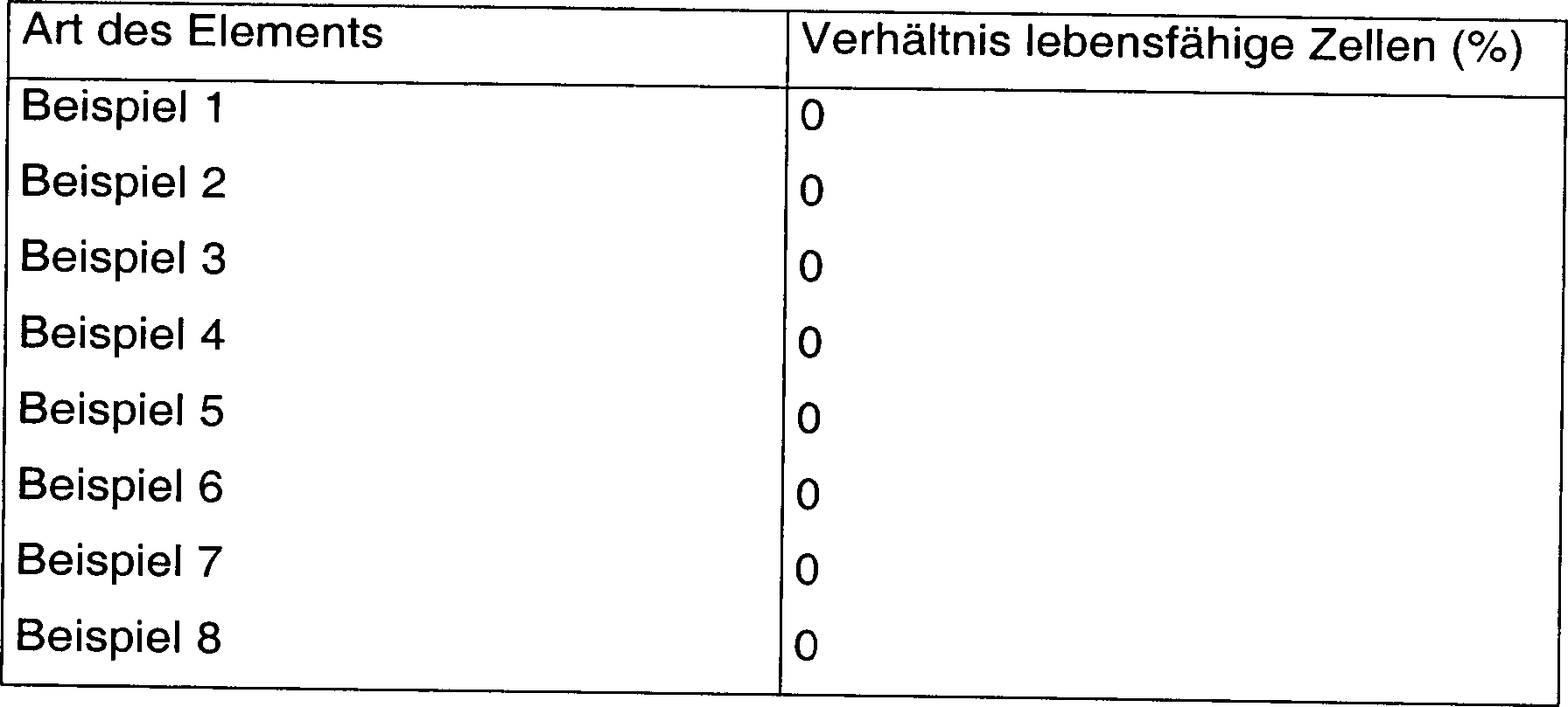
Beispiel 10Example 10
Eine
FRP-Platte (5 cm × 2
cm, 1 cm Dicke) wurde im Substrat
Man ließ Meeresbakterien Vibrio alginolyticus an der Titanfolie der Arbeitselektrode aus der FRP-Platte mit der darauf laminierten Titanfolie anhaften. Eine Spannung von +1,8 V wurde auf die Arbeitselektrode in sterilem Meerwasser 30 Minuten lang aufgebracht und das Verhältnis der lebensfähigen Zellen der Meeresbakterien auf der Titanfolie wurde dann nach dem in Beispiel 9 verwendeten Verfahren gemessen. Es wurde gefunden, dass wenn das Verhältnis von lebensfähigen Zellen vor dem Aufbringen des Potentials mit 100% bestimmt wurde, das Verhältnis von lebensfähigen Zellen nach Aufbringen des Potentials 0% betrug. Ferner wurden das Potential der Titanfolie der Arbeitselektrode, auf die die Spannung von +1,8 V aufgebracht wurde, und das Potential der Titanplatte der Gegenelektrode mit einem Elektrometer unter Verwendung einer Silber/Silberchlorid-Elektrode als Referenzelektrode gemessen. Folglich wurde ein Potential von 1,2 V gegen Ag/AgCl auf die Titanfolie aufgebracht und ein Potential von –0,6 V gegen Ag/AgCl auf die Titanplatte der Gegenelektrode aufgebracht.you left marine bacteria Vibrio alginolyticus on the titanium foil of the working electrode adhering to the FRP plate with the titanium foil laminated thereon. A Voltage of +1.8 V was applied to the working electrode in sterile seawater Applied for 30 minutes and the ratio of viable cells The marine bacteria on the titanium foil was then after that in Example 9 methods used. It was found that if that relationship of viable Cells was determined to be 100% before application of the potential, The relationship of viable Cells after application of the potential was 0%. Furthermore, the Potential of the titanium foil of the working electrode to which the voltage of +1.8 V, and the potential of the titanium plate the counterelectrode with an electrometer using a Silver / silver chloride electrode measured as a reference electrode. consequently A potential of 1.2 V versus Ag / AgCl was applied to the titanium foil and a potential of -0.6 V against Ag / AgCl applied to the titanium plate of the counter electrode.
Anschließend ließ man Meeresbakterien Vibrio alginolyticus an der Oberfläche der Titanplatte als Gegenelektrode anhaften. Eine Spannung von –1,8 V wurde auf die Arbeitselektrode in sterilem Meerwasser 30 Minuten lang aufgebracht und das Verhältnis der lebensfähigen Zellen der Meeresbakterien auf der Titanplatte als Gegenelektrode wurde nach dem in Beispiel 9 verwendeten Verfahren gemessen. Es wurde gefunden, dass wenn das Verhältnis von lebensfähigen Zellen vor dem Aufbringen des Potentials mit 100% bestimmt wurde, das Verhältnis von lebensfähigen Zellen nach Aufbringen des Potentials 0% betrug. Ferner wurden das Potential der Titanplatte als Gegenelektrode, wenn die Spannung von –1,8 V auf die Arbeitselektrode aufgebracht wurde, und das Potential der Titanfolie als Arbeitselektrode mit einem Elektrometer unter Verwendung einer Silber/Silberchlorid-Elektrode als Referenzelektrode gemessen. Folglich wurde ein Potential von 1,2 V gegen Ag/AgCl auf die Titanplatte als Gegenelektrode aufgebracht und ein Potential von –0,6 V gegen Ag/AgCl auf die Titanfolie als Arbeitselektrode aufgebracht.Subsequently, marine bacteria Vibrio alginolyticus were adhered to the surface of the titanium plate as a counter electrode. A voltage of -1.8 V was applied to the working electrode in sterile seawater for 30 minutes, and the ratio of the viable cells of the marine bacteria on the titanium plate as the counter electrode was measured by the method used in Example 9. It was found that when the ratio of viable cells before applying the potential was determined to be 100% was the ratio of viable cells after application of the potential was 0%. Further, the potential of the titanium plate as a counter electrode when the voltage of -1.8 V was applied to the working electrode and the potential of the titanium foil as a working electrode were measured by an electrometer using a silver / silver chloride electrode as a reference electrode. Consequently, a potential of 1.2 V vs. Ag / AgCl was applied to the titanium plate as a counter electrode and a potential of -0.6 V vs. Ag / AgCl was applied to the titanium foil as a working electrode.
Aus den oben angegebenen Ergebnissen konnte festgestellt werden, dass die an der Arbeitselektrode und der Gegenelektrode anhaftenden Meeresbakterien durch Aufbringen der Spannung von der Gleichstromenergieversorgung bei Verändern der Polarität abgetötet werden können.Out From the results given above, it was found that the marine bacteria adhering to the working electrode and the counter electrode by applying the voltage from the DC power supply when changing of polarity killed can be.
Beispiel 11Example 11
Eine
FRP-Platte (5 cm × 2
cm, 1 cm Dicke) wurde im Substrat
Man ließ Meeresbakterien Vibrio alginolyticus an der Titanfolie der Arbeitselektrode aus der FRP-Platte mit der darauf laminierten Titanfolie anhaften. Ein positives Potential von 1,0 V gegen Ag/AgCl wurde mit einem Potentiostat in sterilem Meerwasser 30 Minuten lang auf die Arbeitselektrode aufgebracht und ein Verhältnis von lebensfähigen Meeresbakterien auf der Titanfolie wurde dann nach dem in Beispiel 9 verwendeten Verfahren gemessen. Es wurde gefunden, dass wenn das Verhältnis von lebensfähigen Zellen vor dem Aufbringen des Potentials mit 100% bestimmt wurde, das Verhältnis von lebensfähigen Zellen nach Aufbringen des Potentials 2% betrug.you left marine bacteria Vibrio alginolyticus on the titanium foil of the working electrode adhering to the FRP plate with the titanium foil laminated thereon. One positive potential of 1.0 V against Ag / AgCl was measured with a potentiostat in sterile seawater for 30 minutes on the working electrode upset and a relationship of viable Marine bacteria on the titanium foil were then prepared according to the example 9 methods used. It was found that if that relationship of viable Cells was determined to be 100% before application of the potential, The relationship of viable Cells after application of the potential was 2%.
Ferner wurde ein negatives Potential auf die Arbeitselektrode aufgebracht und das Entfernen der an der Titanfolie anhaftenden Meeresbakterien durchgeführt. Die Meeresbakterien Vibrio alginolyticus hafteten an der Titanfolie der Arbeitselektrode an und ein negatives Potential von –0,6 V gegen Ag/AgCl wurde mit einem Potentiostat in sterilem Meerwasser 10 Minuten lang auf die Arbeitselektrode aufgebracht. Dann wurde das Verhältnis von lebensfähigen Meeresbakterien auf der Titanfolie nach dem in Beispiel 9 verwendeten Verfahren gemessen. Es wurde gefunden, dass wenn das Verhältnis von lebensfähigen Zellen vor dem Aufbringen des negativen Potentials mit 100% bestimmt wurde, das Verhältnis von lebensfähigen Zellen nach Aufbringen des negativen Potentials 45% betrug. Die an der Titanfolie anhaftenden Meeresbakterien wurden durch Aufbringen des negativen Potentials entfernt.Further a negative potential was applied to the working electrode and removing the marine bacteria adhering to the titanium foil carried out. The marine bacteria Vibrio alginolyticus adhered to the titanium foil the working electrode and a negative potential of -0.6 V against Ag / AgCl was treated with a potentiostat in sterile seawater for 10 minutes long applied to the working electrode. Then the ratio of viable Marine bacteria on the titanium foil after that used in Example 9 Measured method. It was found that when the ratio of viable Cells determined prior to application of the negative potential at 100% became, the relationship of viable Cells after application of the negative potential was 45%. The were attached to the titanium foil adhering marine bacteria by applying the negative potential removed.
Aus den oben angegebenen Ergebnissen konnte festgestellt werden, dass die an der Arbeitselektrode anhaftenden Meeresbakterien durch Aufbringen des positiven Potentials abgetötet wurden und durch Aufbringen des negativen Potentials entfernt wurden.Out From the results given above, it was found that by applying the attached to the working electrode marine bacteria of the positive potential killed and removed by applying the negative potential.
Beispiel 12Example 12
Eine
FRP-Platte (5 cm × 2
cm, 1 cm Dicke) wurde im Substrat
Man ließ Meeresbakterien Vibrio alginolyticus am leitfähigen Film anhaften und eine Spannung von +1,8 V wurde in sterilem Meerwasser 30 Minuten lang unter Verwendung einer Gleichstromenergieversorgung aufgebracht. Dann wurden die Meeresbakterien auf jedem der beiden geteilten leitfähigen Filme nach dem in Beispiel 9 verwendeten Verfahren gemessen. Es wurde gefunden, dass wenn das Verhältnis von lebensfähigen Zellen vor dem Aufbringen des Potentials mit 100% bestimmt wurde, das Verhältnis von lebensfähigen Zellen auf einem leitfähigen Film nach Aufbringen des Potentials 0% betrug. Ferner betrug das Verhältnis von lebensfähigen Zellen auf einem anderen leitfähigen Film nach Aufbringen des Potentials 40%.you left marine bacteria Vibrio alginolyticus on conductive Film adhered and a voltage of +1.8 V was in sterile seawater Applied for 30 minutes using a DC power supply. Then the marine bacteria on each of the two divided conductive films measured by the method used in Example 9. It was found that if the ratio of viable Cells was determined to be 100% before application of the potential, The relationship of viable cells on a conductive Film after application of the potential 0%. Furthermore, that was relationship of viable Cells on another conductive Film after applying the potential 40%.
Außerdem wurde das Potential des leitfähigen Films, auf den eine Spannung von 1,8 V aufgebracht wurde, mit einem Elektrometer unter Verwendung einer Silber/Silberchlorid-Elektrode als Referenzelektrode gemessen. Folglich wurde ein Potential von 1,2 V gegen Ag/AgCl auf einen der beiden geteilten leitfähigen Filme aufgebracht und das Potential von –0,6 V gegen Ag/AgCl auf den anderen leitfähigen Film.In addition, the potential of the conductive film was applied to which a voltage of 1.8V was measured with an electrometer using a silver / silver chloride electrode as a reference electrode. Consequently, a potential of 1.2 V vs. Ag / AgCl was applied to one of the two divided conductive films and the potential of -0.6 V vs. Ag / AgCl to the other conductive film.
Aus den oben angegebenen Ergebnissen wurde festgestellt, dass wenn der durch den Isolierteil in zwei Teile unterteilte leitfähige Film auf die Oberfläche der Unterwasserstruktur laminiert ist und die Spannung auf diesen leitfähigen Film mit der Gleichstromenergieversorgung aufgebracht wird, Organismen auf einem der beiden unterteilten leitfähigen Filme abgetötet werden und Organismen auf dem anderen leitfähigen film entfernt werden. Das heißt, Organismen auf den beiden unterteilten leitfähigen Filmen können durch Aufbringen des Potentials bei periodischem Verändern der Polarität abgetötet oder entfernt werden. Bei der Vorrichtung dieses Beispiels wird außerdem die Gegenelektrode überflüssig.Out From the above results, it was found that if the divided by the insulating part in two parts conductive film on the surface the underwater structure is laminated and the tension on this conductive Film is applied with the DC power supply, organisms be killed on one of the two divided conductive films and organisms on the other conductive film are removed. This means, Organisms on the two divided conductive films can pass through Applying the potential killed by periodically changing the polarity or be removed. In the apparatus of this example is also the Counter electrode superfluous.
Beispiel 13Example 13
Im
Substrat
Man ließ Meeresbakterien Vibrio alginolyticus am leitfähigen Film aus Titannitrid der Arbeitselektrode anhaften und Potentiale von 0,8 V und 2 V gegen Ag/AgCl wurden in sterilem Meerwasser 5 Minuten lang aufgebracht. Dann wurde das Verhältnis der lebensfähigen Zellen der Meeresbakterien auf dem leitfähigen Film nach dem in Beispiel 9 verwendeten Verfahren gemessen. Es wurde gefunden, dass wenn das Verhältnis von lebensfähigen Zellen vor dem Aufbringen des Potentials mit 100 bestimmt wurde, das Verhältnis von lebensfähigen Zellen nach Aufbringen des Potentials von 0,8 V gegen Ag/AgCl 63% betrug und das Verhältnis von lebensfähigen Zellen nach Aufbringen des Potentials von 2,0 V gegen Ag/AgCl 0% betrug.you left marine bacteria Vibrio alginolyticus on conductive Titanium nitride film attached to the working electrode and potentials of 0.8V and 2V vs Ag / AgCl were in sterile seawater 5 Applied for minutes. Then the ratio of viable cells of marine bacteria on a conductive film after in example 9 methods used. It was found that if that relationship of viable Cells was determined to be 100 before applying the potential, The relationship of viable Cells after application of the potential of 0.8 V against Ag / AgCl 63% fraud and the ratio of viable Cells after applying the potential of 2.0 V to Ag / AgCl 0% amounted to.
Ferner wurde bei jedem aufgebrachten Potential die Erzeugung von Chlor mit einer Restchloridelektrode untersucht und die Erzeugung von OH-Radikalen mit ESR. Daraus folgte, dass sowohl bei 0,8 V und 2,0 V gegen Ag/AgCl Chlor unter der Erfassungsgrenze war. Außerdem wurden keine OH-Radikale bei 0,8 V gegen Ag/AgCl erzeugt, wurden aber bei 2,0 V gegen Ag/AgCl erzeugt.Further At each applied potential, the generation of chlorine became investigated with a residual chloride electrode and the generation of OH radicals with ESR. It followed that at both 0.8V and 2.0V against Ag / AgCl chlorine was below the detection limit. In addition, were no OH radicals were generated at 0.8 V against Ag / AgCl but were added 2.0 V generated against Ag / AgCl.
Aus diesen Ergebnissen wurde gezeigt, dass Meeresbakterien bei einem relativ niedrigen Potential unter Verwendung von Titannitrid als leitfähigen Film effektiv abgetötet werden können und ferner, dass Meeresbakterien durch Erzeugen von OH-Radikalen vollständig abgetötet werden können.Out These results have shown that marine bacteria in a relatively low potential using titanium nitride as conductive Effectively killed the movie can be and further marine bacteria by generating OH radicals Completely killed can be.
Beispiel 14Example 14
Das Verhältnis von lebensfähigen Zellen von Meeresbakterien auf dem leitfähigen Film aus Titannitrid in der Arbeitselektrode wurde wie in Beispiel 13 gemessen, mit der Ausnahme, dass eine Gegenelektrode erhalten durch Ausbilden von Titannitrid auf einem Titansubstrat durch Sputtern in Beispiel 13 verwendet wurde. Wenn daher das Verhältnis von lebensfähigen Zellen vor dem Aufbringen des Potentials mit 100 bestimmt wurde, betrug das Verhältnis von lebensfähigen Zellen nach Aufbringen des Potentials von 0,8 V gegen Ag/AgCl 68% und das Verhältnis von lebensfähigen Zellen nach Aufbringen des Potentials von 2,0 V gegen Ag/AgCl betrug 0%.The relationship of viable Cells of marine bacteria on the titanium nitride conductive film in The working electrode was measured as in Example 13, with the Except that a counter electrode obtained by forming Titanium nitride on a titanium substrate by sputtering in Example 13 has been used. Therefore, if the ratio of viable cells before application of the potential was 100 The relationship of viable Cells after application of the potential of 0.8 V against Ag / AgCl 68% and the relationship of viable Cells after application of the potential of 2.0 V against Ag / AgCl 0%.
Ferner wurde bei jedem aufgebrachten Potential die Erzeugung von Chlor mit einer Restchloridelektrode untersucht und die Erzeugung von OH-Radikalen mit ESR. Daraus folgte, dass sowohl bei 0,8 V und 2,0 V gegen Ag/AgCl Chlor unter der Erfassungsgrenze war. Außerdem wurden keine OH-Radikale bei 0,8 V gegen Ag/AgCl erzeugt, wurden aber bei 2,0 V gegen Ag/AgCl erzeugt.Further At each applied potential, the generation of chlorine became investigated with a residual chloride electrode and the generation of OH radicals with ESR. It followed that at both 0.8V and 2.0V against Ag / AgCl chlorine was below the detection limit. In addition, were no OH radicals were generated at 0.8 V against Ag / AgCl but were added 2.0 V generated against Ag / AgCl.
Aus diesen Ergebnissen wurde gezeigt, dass Meeresbakterien bei einem relativ niedrigen Potential unter Verwendung von Titannitrid im leitfähigen Film der Arbeitselektrode effektiv abgetötet werden können, wenn die Gegenelektrode verwendet wird, bei der Titannitrid auf dem Titansubstrat durch Sputtern in Beispiel 13 ausgebildet ist, und ferner, dass Meeresbakterien durch Erzeugen des OH-Radikals vollständig abgetötet werden können.Out These results have shown that marine bacteria in a relatively low potential using titanium nitride in the conductive Film of the working electrode can be effectively killed if the counter electrode is used, with the titanium nitride on the titanium substrate formed by sputtering in Example 13, and further that Marine bacteria are completely killed by generating the OH radical can.
Claims (21)
Applications Claiming Priority (11)
| Application Number | Priority Date | Filing Date | Title |
|---|---|---|---|
| JP10062159A JPH11244861A (en) | 1998-02-26 | 1998-02-26 | Antifouling device for underwater structure and electrochemical control method of living thing |
| JP6215998 | 1998-02-26 | ||
| JP8495398 | 1998-03-16 | ||
| JP8495398A JPH11264062A (en) | 1998-03-16 | 1998-03-16 | Method for producing metal nitride, its thermal spray coating and member for electrochemical biological control or antifouling |
| JP13603998A JP3867401B2 (en) | 1998-04-30 | 1998-04-30 | Aquatic antifouling equipment |
| JP13603998 | 1998-04-30 | ||
| JP16422998A JPH11333465A (en) | 1998-05-28 | 1998-05-28 | Electrochemical biological control or antifouling components |
| JP16422998 | 1998-05-28 | ||
| JP19667798 | 1998-06-26 | ||
| JP10196677A JP2000008338A (en) | 1998-06-26 | 1998-06-26 | Antifouling equipment for underwater structures |
| PCT/JP1998/003784 WO1999043618A1 (en) | 1998-02-26 | 1998-08-26 | Electrochemical antifouling device comprising underwater structure and method of producing underwater structure used for the device |
Publications (2)
| Publication Number | Publication Date |
|---|---|
| DE69829366D1 DE69829366D1 (en) | 2005-04-21 |
| DE69829366T2 true DE69829366T2 (en) | 2006-04-06 |
Family
ID=27523695
Family Applications (1)
| Application Number | Title | Priority Date | Filing Date |
|---|---|---|---|
| DE69829366T Expired - Fee Related DE69829366T2 (en) | 1998-02-26 | 1998-08-26 | ELECTROCHEMICAL ANTIFOULING DEVICE WITH UNDERWATER STRUCTURE AND METHOD FOR PRODUCING THE UNDERWATER STRUCTURE |
Country Status (5)
| Country | Link |
|---|---|
| US (1) | US6197168B1 (en) |
| EP (1) | EP0985639B1 (en) |
| CA (1) | CA2288141A1 (en) |
| DE (1) | DE69829366T2 (en) |
| WO (1) | WO1999043618A1 (en) |
Families Citing this family (24)
| Publication number | Priority date | Publication date | Assignee | Title |
|---|---|---|---|---|
| AUPP958199A0 (en) * | 1999-04-01 | 1999-04-29 | Barnacle Guard System Pty Ltd | An anode for use in a marine environment |
| EP1084947A1 (en) * | 1999-09-17 | 2001-03-21 | Magnus Kvant | A method of durably and lastingly protect a surface in contact with water from biological fouling |
| NL1017412C2 (en) * | 2001-02-21 | 2002-08-22 | Tno | Method for protecting surfaces against biological fouling. |
| US7324011B2 (en) * | 2004-04-14 | 2008-01-29 | Battelle Energy Alliance, Llc | Method and system for pipeline communication |
| US7276264B1 (en) * | 2002-02-11 | 2007-10-02 | Battelle Energy Alliance, Llc | Methods for coating conduit interior surfaces utilizing a thermal spray gun with extension arm |
| US6889557B2 (en) * | 2002-02-11 | 2005-05-10 | Bechtel Bwxt Idaho, Llc | Network and topology for identifying, locating and quantifying physical phenomena, systems and methods for employing same |
| US7334485B2 (en) | 2002-02-11 | 2008-02-26 | Battelle Energy Alliance, Llc | System, method and computer-readable medium for locating physical phenomena |
| US6916502B2 (en) * | 2002-02-11 | 2005-07-12 | Battelle Energy Alliance, Llc | Systems and methods for coating conduit interior surfaces utilizing a thermal spray gun with extension arm |
| KR100538009B1 (en) * | 2003-02-13 | 2005-12-21 | 정명국 | Anti-fouling and eliminating system for aquatic organisms |
| DE10324228B4 (en) * | 2003-05-28 | 2006-02-16 | Rittal Gmbh & Co. Kg | Cooling device for an offshore wind turbine |
| DE102004005303A1 (en) * | 2004-01-29 | 2005-08-11 | Gao, Yuan, Dipl.-Ing. | Current supply in electrolytic water disinfection online monitoring with a two- electrode sensor has zero current flow at pole reversal |
| US7131877B1 (en) * | 2004-03-24 | 2006-11-07 | Brunswick Corporation | Method for protecting a marine propulsion system |
| DE102005049388A1 (en) * | 2005-10-15 | 2007-04-19 | Dechema Gesellschaft Für Chemische Technik Und Biotechnologie E.V. | Prevention or reduction of biofilm formation on surface e.g. membrane or other electrically insulating surface used in aqueous medium involves making surface polarizable with conductive coating e.g. of metal or organic polymer |
| WO2008020585A1 (en) * | 2006-08-14 | 2008-02-21 | Nakayama Steel Works, Ltd. | Method and apparatus for forming amorphous coating film |
| US20080218709A1 (en) * | 2007-03-07 | 2008-09-11 | Asml Netherlands B.V. | Removal of deposition on an element of a lithographic apparatus |
| US7686936B1 (en) * | 2007-05-01 | 2010-03-30 | Brunswick Corporation | Method for inhibiting fouling of a submerged surface |
| US8555543B2 (en) | 2011-01-24 | 2013-10-15 | Paul N. Baldassano | Salt water kill of a soft tissue organism |
| US20140331912A1 (en) * | 2013-05-07 | 2014-11-13 | Kee-Rong Wu | Apparatus using an electro-catalytic coating to reduce ship's friction and prevent biofouling |
| CN104724271A (en) * | 2015-03-18 | 2015-06-24 | 青岛双瑞海洋环境工程股份有限公司 | Marine portable propeller anti-fouling device |
| DE102015223583B4 (en) | 2015-11-27 | 2022-08-25 | BSH Hausgeräte GmbH | Water-bearing household appliance with an electrochemically polarizable inner surface and method for its operation |
| DE102015223616B4 (en) | 2015-11-30 | 2019-08-14 | BSH Hausgeräte GmbH | Household appliance with electrolytic biofilm control and method for its operation |
| KR102547429B1 (en) * | 2016-12-27 | 2023-06-23 | 코닌클리케 필립스 엔.브이. | Devices for anti-fouling of protective surfaces |
| EP3481151A1 (en) * | 2017-11-01 | 2019-05-08 | Koninklijke Philips N.V. | An electric current supply system, designed to be at least partially submerged in an electrically conductive liquid during operation thereof |
| CN110901847B (en) * | 2019-12-20 | 2021-03-05 | 山东交通学院 | A prevention and control system and monitoring method for marine marine biological attachments |
Family Cites Families (7)
| Publication number | Priority date | Publication date | Assignee | Title |
|---|---|---|---|---|
| JPH0724822B2 (en) * | 1990-07-23 | 1995-03-22 | 大機ゴム工業株式会社 | Antifouling method and antifouling device |
| JP3385618B2 (en) | 1991-04-10 | 2003-03-10 | 大機エンジニアリング株式会社 | Antifouling device |
| JP3576569B2 (en) | 1992-09-17 | 2004-10-13 | オカモト株式会社 | Composite sheet and binder formed from the sheet |
| JP2842161B2 (en) | 1993-07-09 | 1998-12-24 | 株式会社イナックス | Finishing method of green body |
| FI103190B (en) * | 1994-11-01 | 1999-05-14 | Savcor Process Oy | Procedure for preventing the growth of organisms on structural surfaces in liquid embeds |
| JPH09248554A (en) * | 1996-03-12 | 1997-09-22 | Pentel Kk | Electrochemical control method and antifouling method for aquatic organisms |
| JP3491081B2 (en) * | 1996-12-26 | 2004-01-26 | ぺんてる株式会社 | Electrochemical biological control or antifouling components |
-
1998
- 1998-08-26 DE DE69829366T patent/DE69829366T2/en not_active Expired - Fee Related
- 1998-08-26 CA CA002288141A patent/CA2288141A1/en not_active Abandoned
- 1998-08-26 EP EP98940552A patent/EP0985639B1/en not_active Expired - Lifetime
- 1998-08-26 WO PCT/JP1998/003784 patent/WO1999043618A1/en not_active Ceased
-
1999
- 1999-10-25 US US09/426,658 patent/US6197168B1/en not_active Expired - Fee Related
Also Published As
| Publication number | Publication date |
|---|---|
| EP0985639A4 (en) | 2003-03-26 |
| DE69829366D1 (en) | 2005-04-21 |
| WO1999043618A1 (en) | 1999-09-02 |
| EP0985639A1 (en) | 2000-03-15 |
| EP0985639B1 (en) | 2005-03-16 |
| US6197168B1 (en) | 2001-03-06 |
| CA2288141A1 (en) | 1999-09-02 |
Similar Documents
| Publication | Publication Date | Title |
|---|---|---|
| DE69829366T2 (en) | ELECTROCHEMICAL ANTIFOULING DEVICE WITH UNDERWATER STRUCTURE AND METHOD FOR PRODUCING THE UNDERWATER STRUCTURE | |
| DE69015517T2 (en) | Continuous electroplating of electrically conductive foam. | |
| DE69519702T2 (en) | Method and device for producing ionized water | |
| DE2644035C3 (en) | Process for the electrodeposition of a dispersion layer | |
| DE69900286T2 (en) | METHOD FOR THE ELECTRODEPOSITION OF METAL LAYERS ON PARTICULATE SUBSTANCES WITH HIGH DEPOSITION SPEED AND HIGH CURRENT DENSITY | |
| DE3307748A1 (en) | METHOD FOR TREATING A METAL FILM IN ORDER TO IMPROVE YOUR ADHESION | |
| EP2316584B1 (en) | Electrochemical anti-fouling system for structures wetted by sea water | |
| CN105386103A (en) | Material and process for electrochemical deposition of nanolaminated brass alloys | |
| KR102274990B1 (en) | surface treatment steel plate | |
| Wake et al. | Development of an electrochemical antifouling system for seawater cooling pipelines of power plants using titanium | |
| EP0668374A1 (en) | Process for electroplating one or both sides of a thin polymer foil provided with a conductive coating | |
| El Sayed et al. | Nanocrystalline silver coatings on steel by electrodeposition from non-polluting aqueous baths and its antibacterial activity | |
| EP2262929B1 (en) | Method for the electrochemical coating of a substrate by brush plating and device for carrying out said method | |
| DE69302941T2 (en) | Anti-rot materials | |
| EP2483455A2 (en) | Method for electrochemical coating of a substrate by means of brush plating and device for carrying out said method | |
| Khan et al. | Fabrication and characterisation of electrodeposited and magnetron sputtered thin films | |
| EP2212447A2 (en) | Gold-containing nickel layer | |
| JPH11264062A (en) | Method for producing metal nitride, its thermal spray coating and member for electrochemical biological control or antifouling | |
| DE2922789C2 (en) | Steel coated with manganese, process for its manufacture and its use | |
| EP2980167B1 (en) | Antifouling coating and its use and method for protecting surfaces from biofouling | |
| EP2454204A2 (en) | Apparatus and method for the bioelectrochemical denitrification of fluids | |
| Wehrspohn et al. | Prevention of Biofouling: Electrochemical and Anti-Adhesion Technologies to Protect Ship Hulls and Membrane Modules from Biofouling | |
| WO2005103330A1 (en) | Method and device for coating an object | |
| JPH02171129A (en) | Antifouling method for fishing nets | |
| Emalya et al. | Enhancing Energy Production and Pollutants Removal in Landfill Leachate Using Anode-Modified Sediment Microbial Fuel Cells |
Legal Events
| Date | Code | Title | Description |
|---|---|---|---|
| 8364 | No opposition during term of opposition | ||
| 8339 | Ceased/non-payment of the annual fee |